
Design and Implementation of Fuzzy logic based Multilevel Inverter for Micro Grids considering Bidirectional Power Flow through the Interlinking Converters
1 D. Vyshnavi, 2 Dr J. Sreenivasulu, 3Dr. M. Anka Rao***
Abstract:
The research focuses on the bidirectional power flow in ac/dc hybrid microgrid (HMG) using the interlinking converter (IC) The primary difficulty is managing power flows between all sources located on the two types of sub-grids, which is more difficult than earlier attempts created for only ac or dc microgrids. Not much research has been done into this broader spectrum of control. It would require the synchronised operation of dc sources, ac sources, and converters to function properly. The converters might redirect power from an alternating current (ac) to a direct current (dc) sub-microgrid. This converter allows load requirements to be met despite an absence of power in a sub-microgrid comprised of distributed generators (DGs) with droop controllers, which are critical to the system’s stability during islanding. In this study, we investigate how the direction of power flow affects the small-signal stability of islanded droop-based HMGs. We begin by developing a linearised state-space model of an HMG. Time-domain simulations in MATLAB/Simulink show that increasing generation on the dc subgrid improves the HMG stability margin overall during islanding.
Keywords: interlinking converter (IC), hybrid microgrid (HMG)

I. INTRODUCTION:
New energy is consumed by microgrids relatively efficiently [1, 2]. More and more research is turning to DC hybrid microgrids [3, 4], which combine the best features of DC and AC microgrids. Converters typically supportbusvoltages,andthecapacityofislandedAC-DC hybrid microgrids is restricted. This means that the converters' interconnections are vital to the reliable operationofAC-DChybridmicrogrids.Recently,theidea of forming a hybrid microgrid by linking isolated ac and dc microgrids via bidirectional ICs has been proposed [5,6].Abidirectionalinterlinkingconverter(IC)operates in tandem with the ACS and DCS to facilitate power transmission between the two systems in hybrid systems[3].Powercontrol systemsforthemanagement ofACSorDCSarereviewedin[7],andeachsub-gridcan be run in either grid-connected or islanded mode. Many organisations use decentralised control techniques based on typical droop features. [8]. However, most published power management techniques dealt exclusivelywithACSorDCS settings.[9],introducedthe idea of a droop controller for ACS. To maintain power sharing in ACSs, a decentralised control technique with an additional droop gain is presented in [10]. Adaptive droopgainusingavirtualvoltageandfrequencyframeis provided in [11] to boost the system's efficiency. This techniquepermitsautonomousregulationofpowerflow.
However, slight variations in ac frequency and voltage output may enhance inter-sub grid circulating currents. Power penetration, control methods, loads, line conditions, etc., are also claimed to affect frequency and voltage[12].Aphasecompensationtransferfunctionhas been incorporated into the unified power control loop [13] to improve the ac frequency and voltage. [14] presentsadroopapproachforcoordinatingpowerflows andcoveringadequate powersharingamongmanysubgrids. The mathematical model of microgrid stability analysis has been the primary focus of work aiming to increase its stability [15]. Maximising droop advantages enhance microgrid reliability. Predictive and computational precision are both impacted by the microgrid model. Microgrid stability analysis needs improvement;however,manystudieshavebeendoneon proposed methods to trigger DGs’ changes in load to make instantaneous adjustments to their output power, allowing them to participate actively in voltage managementandmicrogridfrequencycontrol.
Nikos [16] has improved AC/DC hybrid microgrid controller method, which was applied to the model, control, and simulate the microgrid. Employing a linear droop controller such as voltage feedback led to increased microgrid voltage stability in the islanded mode To account for network dynamics and loads, a small-signal model of the ac and dc subgrids is created [17]. As a further point, the authors of [18] conducted a thorough stability analysis and found that strict management of dc/dc converters in dc subgrids would reduce HMG stability. The effect of droop gains on stabilitymarginswasalsoexaminedinaworkdescribed in [19], which offered a small-signal model of the HMG. Instability may result if the droop constant is more significant, which could cause the dominant modes to move to the right half of the complex plane. Most publishedworkshaveanalysedtheeffectsofdroopgains on HMG stability or dealt with the creation of control techniquesfortheIC. Theimpactofthetwo-wayflowof power on HMG stability is first examined in this paper. The direction of power flow through the IC can be changedbyadjustingtheloadontheacanddc subgrids. Througheigenvalueanalysis,weexaminehowthepower flow between the ac and dc subgrids affects the HMG's stabilitymargin.Toconfirmtheeffectofinterconnection coupling(IC)powerexchangebetweensubgridsonHMG stability with various topologies, simulations are run in thetimedomain.
II. SYSTEM STRUCTURE:
Figure 1 depicts a straightforward hybrid ac/dc microgrid. 1. It comprises an ac microgrid with traditional DG sources, a dc microgrid with two dc type sources, and an IC that connects the two microgrids. Individual loads are also included in each of these microgrids. In addition, the ac microgrid connects the hybrid microgrid to the primary utility grid during regular grid operation. In general, microgrids are believed to function in grid-connected or islanding
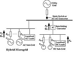
modes. Power conversion is minimised by similar groupingsources,storages,andloadsintosmaller,more manageable sub-grids when possible. One or more converters may be used to connect the sub-grids, with the number needed depending on the converter ratings and the sub-grid capacities. However, many converters areusedtoconnectthesub-grids;theirprimaryfunction is to allow for the bidirectional movement of electricity between the sub-grids in response to changes in supply and demand. Following formation, the hybrid microgrid canbeconnectedtotheACutilitymainsviaanintelligent transferswitch,justasconventionalACmicrogridsdo
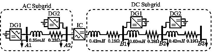
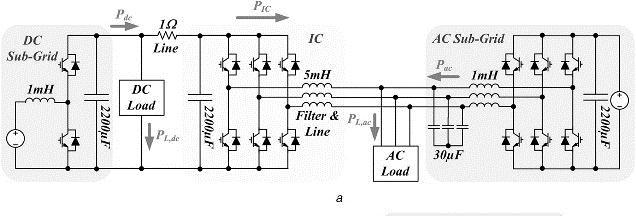
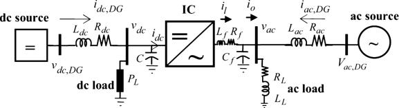
The schematic of the microgrid is shown in Figure 2. It consists of two AC sections, one DC section, and an interface converter. When one side of the system's load or generation changes, it might influence the other. Any additional electricityneededtokeepeverythingrunning smoothly comes from the opposite end of the bus. The DC voltage and AC frequency are stabilised, and the controllers are developed in a decentralised model to createpowerbasedontheneedsofeachcomponent.
Fig. 3 shows a simplified schematic representation of a hybrid microgrid (HMG) with ac and dc distributed generators (DGs), ac anddcdistributedloads,andanIC. Itispossibleforamicrogridtofunctioneitherasagridconnected or an island system The central power grid controls voltage and frequency in grid-connected mode. Power sharing across DG units and voltage and frequency regulation are tasks handled by microgrid controllers in the interconnected mode [20]-[22]. Connecting to the microgrid, many DG units use electronic power inverters voltage-sourced converters (VSC) [23], [25]. Improved power quality, voltage regulation, fault current coordination, and reactive
power (VAr) support are the primary benefits of an interfacebasedonpowerelectronics[26].However,low inertia in inverter-based microgrids makes it harder to keep them stable and dampen oscillations. Both nonlinear and linear methods have been presented for controlling the current or voltage in three-phase VSCs. However, there is no guarantee that nonlinear methods will outperform linear ones, and they add complexity to the system in terms of design and implementation. The two primary categories of linear methods are those that use a stationary reference frame (SRF) and those that use a rotating reference frame (RRF). A large steadystate error is common in SRF-based systems, but RRFbased methods can achieve perfect stability. The most common current and voltage regulators that apply RRF theory are PI-based. PI-based controllers are typically used for zero-level control in inverter-based microgrids. Despite its usefulness, popularity, and ease of tuning, PI controlsuffersfromaslowreaction,abigovershoot,and a lengthy settling period. It's not very sturdy, and the axesaren't decoupled. For microgridstomaximise asset utilisation and prevent violations of operational constraints, voltage, current stability, and transient behaviour must be significantly enhanced. The research uses time-domain simulations of a single DG unit to demonstrate that, compared to PI-based controllers, the FUZZY-based solution provides improved transient performance and is more resistant to uncertainties in systemparameters.
•Evenwithouta quick communicationlink betweenthe sources, an overloaded source placed in the hybrid microgriddidnotcreateasinglepointoffailure.
• Regardless of the location where the load transients are triggered, individual source variations are always kept low. Certain sources, like fuel cells, may appreciate smaller modifications; nevertheless, because of their often-delayed responses, these sources should avoid havingtheirparameterschangedtoomuch.
•Sourcecapacitiescanbesharedbetweenthetwotypes ofsub-grids,henceallowing backupreserve within each sub-grid to be reduced considerably. These advantages cannot be realized by just relying on droop-controlled sources.
III. INTERLINKING CONTROL (IC) BETWEEN SUB-GRIDS:
Coordination across sub-grids is necessary for backup purposes regardless of the method used to distribute power equitably within each sub-grid. This must be accomplished before the ac or dc sub-grid sources may be included in the hybrid microgrid's overall powersharing scheme. The benefits of such a larger scale of powersharingcanbesummedupasfollows.
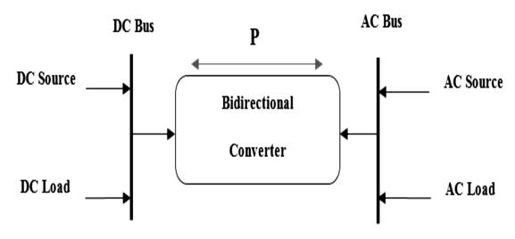
The interface converter between AC and DC sections shouldhavehighrectifierandinvertercapabilities.Ifthe output power of the AC side is less than its power consumption,itwouldbenecessarytoreceivepartofthe required power through the DC side. In this case, the converteractsasaninverter.Also,iftheoutputpowerof the DC side is low, it is necessary to receive part of the required power through the AC side. In this case, the converterfunctionsasarectifier.Theconverterreceives the changes according to DC and AC voltage and frequencyandactsaccordingly. Intheislandingmodeof operation, and during light loading of the dc part, the demanded power is shared among the dc sources using thedroopcharacteristics.
3.1MODELINGOFICINTHEHMG:
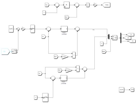
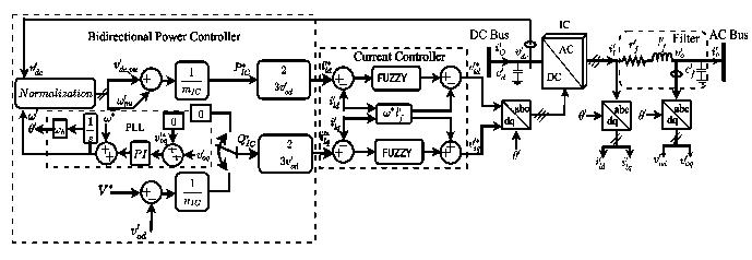
The overall structure of the IC is depicted in Fig. 5. This control scheme implements a bidirectional power controller followed by a current controller [28]. The state equations of the IC current controller and the output filter are the same as [9-13] the IC employs a phase-locked loop (PLL) to determine the output ac voltage frequency (��) and angle (��) at its ac terminal. ThestateequationofthePLLisdescribedby
Where istheinteglartermofPLLandwhere Kpp and Kip arethePIgainsofthePLL.
Furthermore, the ac frequency (��) and dc voltage (Vdc) are brought to a per-unit range of [-1; 1], through a normalisation process adopted from [9]. The IC is used to transfer power between the ac and dc subgrids. The fuzzycontrollercanbeusedinsteadofadroopcontroller whenonlyoneICexistswherethePIcontrollerisusedin the existing system. The IC is primarily concerned with the active power transfer, so the IC reference reactive power (Q*IC) can be set to zero when the power flows from the dc to ac subgrid. When supporting an ac subgridwithlimitedreactivepowerresources,theICcan contribute to reactive power sharing. The stability analysis is mainly directed towards the bidirectional activepowerflowthroughtheIC.
IV. Fuzzy logic controller:
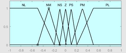
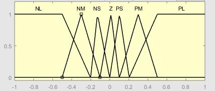
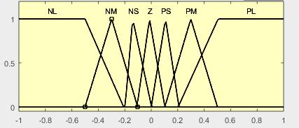
Thefuzzylogicsystemisaflexibleandrobustcontroller thatissuitableforallpracticalapplicationsineveryfield oftechnology.Itcanapproximateanynonlinearfunction to the desired level with high accuracy Here we are using49rules,andthetableisgivenbelow
Table1:
V.SIMULATION RESULTS:
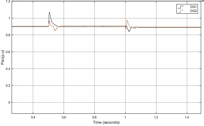
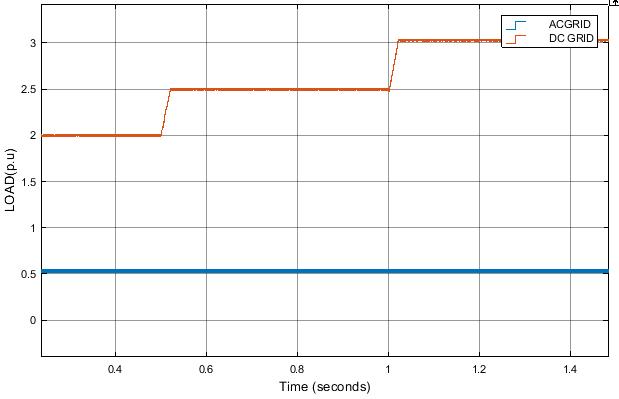
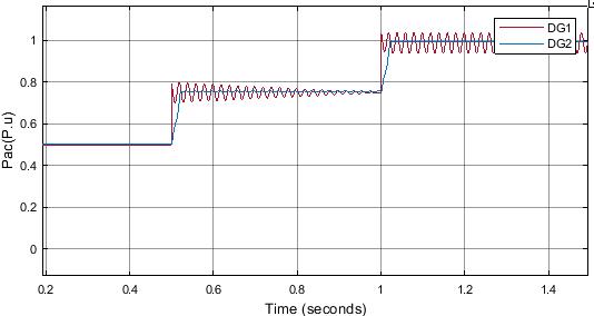
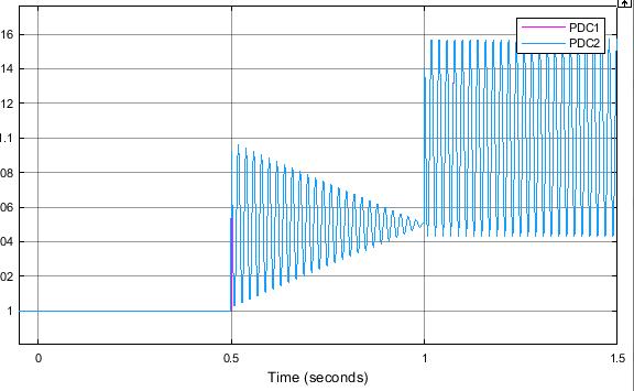
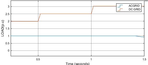
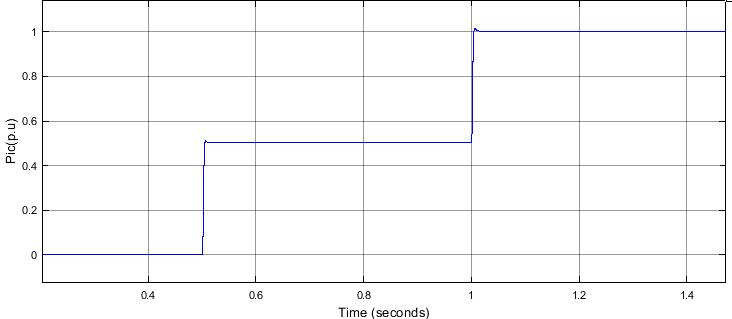
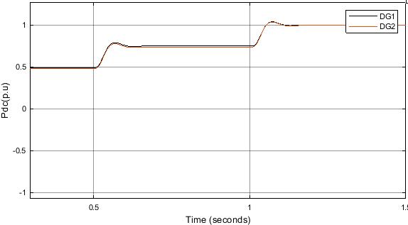
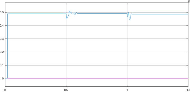
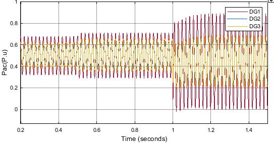
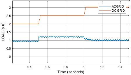
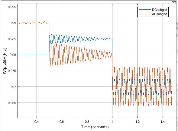
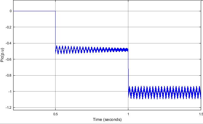
Atotaldcpowerdemandof1p.u.isappliedtotheHMG's dc subgrid in Fig. 2. The ac subgrid's ac loads are adjusted so that, from time t = 0 to 0.5 s, 2.0 p.u. of ac power is applied. 1) The ac subgrid is loaded with 2.0 p.u. for the duration of time t = 0 to 0.5 s. 2) By connecting an additional 0.5 p.u load at Bus-A1, the ac subgrid is overloaded at 2.5 p.u at time t = 0.5 s. 3) By addinga second0.5p.uloadatBus-A2,thetotalloadon theacsubgridrisesto3.0p.uatt=1s.asshownat9(e). Additionally, Figs. 9a and 9c show the output power responses of the DGs for the ac and dc subgrids, respectively. Fig. 9b displays the IC's dynamic response to the power flowing through it. Figure 9d shows a plot of the measured dc voltage and ac frequency at the IC terminals. The two DGs in the dc subgrid are found to producesimilaramountsofpowerduetothelowdcline resistance. This case study shows that a better dynamic performance may be obtained as the active power flow fromthedctoacsubgridincreases. (a)
When active power is transferred from the dc to the ac subgridandtheICisaskedtoprovidereactivepowerto theac subgrid,the(QIC-V) droopcontrol loopfor the IC isactivated.ItisfoundthattheICsharestheacsubgrid's needforreactivepowerinresponsetoanincreaseinac load based on its droop characteristics. While the ac subgrid increased its need for power, the IC would continue injecting reactive power as long as its capacity allowed.Ifthereactivepowerresourcesoftheacsubgrid are limited, these simulation results confirm to the IC capabilities of the reactive power support. An oscillatory-free dynamic behaviour is maintained using fuzzy controller of the power flow from the dc to the ac subgrid.
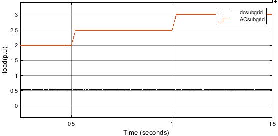
The effect of power transfer from the AC grid to the DC subgrid is measured and analysed in terms of its effect on HMG reliability. A total of 1.0 p.u of ac power is required to be drawn from the ac subgrid for the entire period,whilethedcsubgridisloadedat2.0p.ufromt= 0 to t = 0.5 s, 2.5 p.u from t = 0.5 to t = 1 s, and 3.0 p.u fromt=1tot=1.5s.
The ac subgrid's Bus-A1 is also wired to a 1.0 p.u. generating capacity DG. As an alternative, switching off the DG unit at Bus-B2 reduces the dc subgrid's powergenerating capability to 1.0 p.u. This results in an increase of 3.0 p.u. in the ac subgrid's total power generation capacity. As shown in Fig. 11a, the ac and dc subgrids require 1.0 and 2.0 p.u. of power for the time interval t=0to0.5s.InFig. 11b,thedynamicresponses
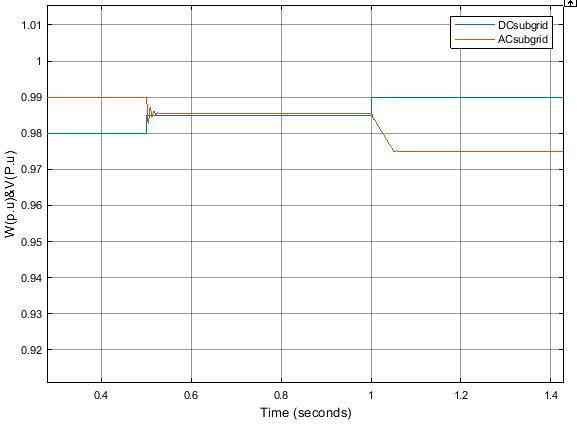
of the DGs' ac and dc subgrid power outputs are shown, and in Fig. 11c, it is seen that the IC transfers 1.0 p.u from the ac to the dc subgrid at t = 0 to 0.5 s to supply the dc load. Figure 11d depicts the alternating current frequencyanddirectcurrentvoltage.
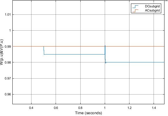
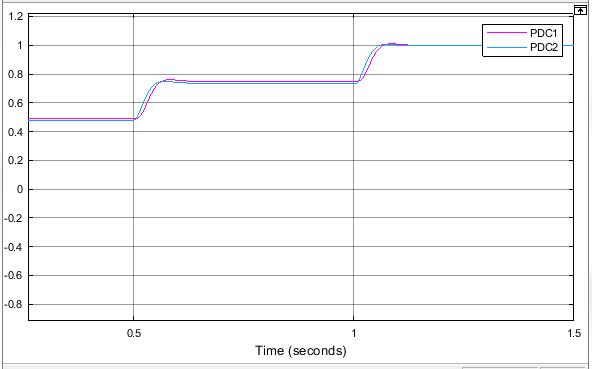
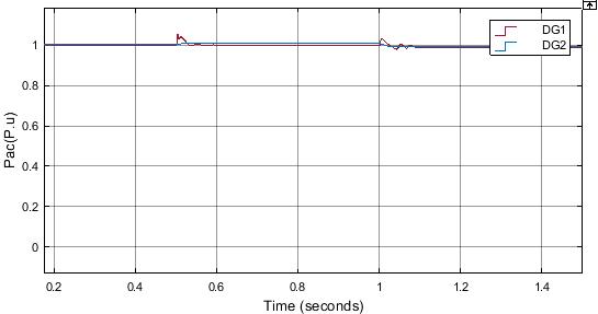
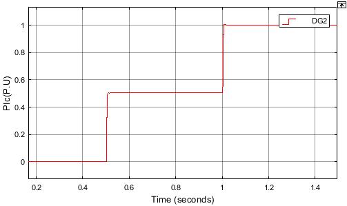
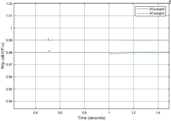
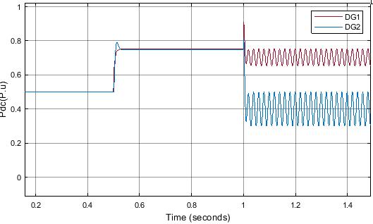
When DC generation capacity is increased, the dynamic system response of an ac/dc hybrid microgrid (HMG) is studied. From t = 0 to 0.5 s, the ac and dc subgrids' powerrequirementsare0.8and1.8p.u.,respectively,as shown in Fig. 13a. In Fig. 13b and 13c, we see the dynamic response of the DGs' power outputs in both ac and dc subgrids. The extra DG unit clearly aids in the distributionofelectricityinsidethedcsubgrid.Asshown in Fig. 13c, the three DGs in the dc subgrid contribute equallytotheriseinthedcloadatt=0.5and1.0s.Fig. 13e shows that the ac frequency and the dc voltage are stable. Incorporating more DGs into the dc subgrid, as indicated by the results, would maintain the subgrid's currentlevelofdynamicperformance.
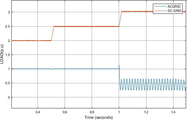
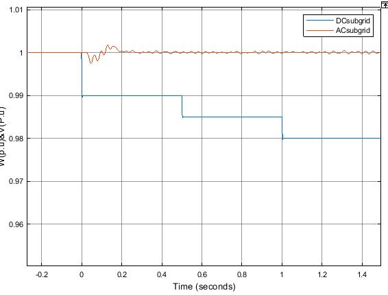
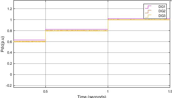
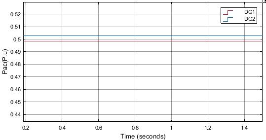
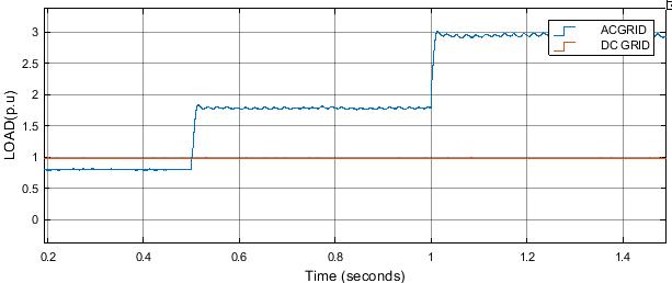
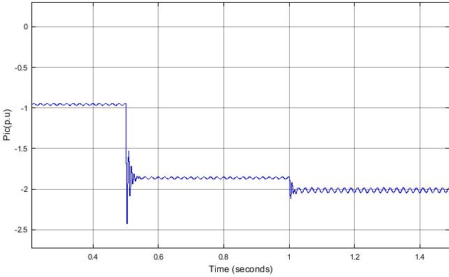
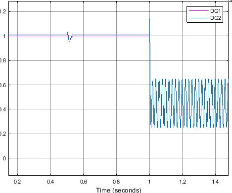
FIGURE14.Dynamicresponsesforactodcpowerflow conditionincaseofdroopcontrolintheacsubgrid.
As can be seen from the simulation results, even when the DGs in the ac subgrid take on distinct droop characteristics, droop-based HMGs will still display an oscillating behaviour for the ac to dc power flow direction. As a result, changing the values of the droop controllers will not fix the system's instability. For this reason, fuzzy control is used in this investigation to dampen the oscillator's behaviour while maintaining its superiorperformance.
Conclusion:
The impact of the power flow between ac and dc subgrids in an HMG on the stability of the system. It is observed that when the power flow from the ac to dc subgrid increases, the stability margin of the HMG may be reduced. This is because when the power is exchanged from the ac to dc subgrid, the dynamics associatedwiththeacsubgridhavegreaterinfluenceon theHMGstabilityascomparedtothoseofthedcsubgrid. Additionally, an increase in the generation capacity of theacsubgridincreasesthepowerflowfromtheactodc subgrid to supply the dc load power, which could degrade the stability of the HMG. The simulation results show that droop-based HMGs oscillate in the ac to dc power flow direction even when the DGs in the ac subgrid have separate droop characteristics. Thus, adjusting the droop controller values won't stabilise the system. Fuzzy control dampens the oscillator's behaviour while preserving its exceptional performance inthisstudy.
REFERENCES:
[1] Ahmed, M., Meegahapola, L., Vahidnia, A., Datta, M.: Stability and control aspects of microgrid architectures–A comprehensive review. IEEEAccess. 08(1), 0144730–144766(2020)
[2]AdrianMihaiIuoras,SorinIonuSalcu,CalinGheorghe Rusu, Calin Marginean, Petre Dorel Teodosescu “Power factor compensation for a single-phase AC-DC Hybrid Micro-Grid”978-1-7281-6990-3,2020
[3] Gupta, A., Doolla, S., Chatterjee, K.: Hybrid AC–DC Microgrid: ’ Systematic evaluation of control strategies. IEEETrans.SmartGrid.9(4),3830–3843(2018)
[4]Bagherzadeh,M.,Karshenas,H.R.,GolsorkhiEsfahani, M.S.: Control method for improvement of power quality insingleinterlinkingconverterhybridAC-DCmicrogrids. IETSmartGrid.4(4),414–428(2021)
[5]. Rasoolzadeh, A., Salmasi, F.R.: Reduced-order dynamicmodelfordroop-controlledinverter/converterbasedlow-voltagehybridAC/DCmicrogrids–part1:AC sub-microgrid.IETSmartGrid.1(4),123–133(2018)
[6] Y. Han, H. Li, P. Shen, E. A. A. Coelho, and J. M. Guerrero,“ReviewofActiveandReactivePowerSharing Strategies in Hierarchical Controlled Microgrids,” IEEE Trans. Power Electron., vol. 32, no. 3, pp. 2427–2451, May 2017. [5] P. Kundur, Power System Stability and Control,vol.23.2006
[7]. Lv, Z., Zhang, Y., Xia, Y., Wei, W.: Adjustable inertia implemented bidirectional power converter in hybrid AC/DC microgrid. IET Gener.Transm. Distrib. 14(17), 3594–3603(2020)
[8]M.C.Chandorkar,D.M.Divan,andR.Adapa,“Control of parallel connected inverters in standalone ac supply systems,” IEEE Trans. Ind. Appl., vol. 29, no. 1, pp. 136–143,Jan.1993.
[9]H.Liang,B.J.Choi,W.Zhuang,andX.Shen,“Stability enhancement of decentralized inverter control through wireless communications in microgrids,” IEEE Trans. SmartGrid,vol.4,no.1,pp.321–331,Aug.2013.
[10] Y. Li and Y. W. Li, “Power management of inverter interfaced autonomous microgrid based on virtual frequency-voltageframe,”IEEETrans.SmartGrid,vol.2, no.1,pp.30–40,Mar.2011.
[11] J. Zhou, H. Zhang, Q. Sun, D. Ma, and B. Huang, “Event-based distributed active power sharing control for interconnected AC and DC Microgrids,” IEEE Trans. SmartGrid,pp.1–1,2017.[10]A.A.A.RadwanandY.A.R. I. Mohamed, “Networked control and power management ofAC./DChybrid microgrids,”IEEE Syst. J., pp.1–12,2014.
[12] “IEEE guide for conducting distribution impact studies for distributed resource interconnection,” IEEE Std1547.7-2013,pp.1–137,Feb.2014.
[13] X. Li et al., “A unified control for the dc-ac interlinking converters in hybrid AC/DC microgrids,” IEEETrans.SmartGrid,pp.1–1,2017.
[14] N. Eghtedarpour and E. Farjah, “Power control and management in a hybrid AC/DC microgrid,” IEEE Trans. SmartGrid,vol.5,no.3,pp.1494–1505,May2014
[15] Malik, S.M., Ai, X., Sun, Y., Zhengqi, C., Shupeng, Z.J.I.G., Transmission and Distribution, "Voltage and frequencycontrolstrategiesofhybridac/dcmicrogrid:A review", IET Generation, Transmission & Distribution, Vol. 11, No. 2, (2017), 303-313, doi: 10.1049/ietgtd.2016.0791.
[16] Hatziargyriou, N., "Microgrids: Architectures and control,JohnWiley&Sons,(2014).
[17] A. A. Radwan and Y. A.-R. I. Mohamed, ``Networked control and power management of AC/DC hybrid microgrids,'' IEEE Syst. J., vol. 11, no. 3, pp. 1662-1673, Sep.2014.
[18] A. A. A. Radwan and Y. A.-R.-I. Mohamed, ``Assessmentandmitigation ofinteractiondynamicsin hybridAC/DC distribution generation systems,'' IEEE Trans.SmartGrid,vol.3,no.3,pp.1382-1393,Sep.2012.
[19] D. K. Dheer, S. Doolla, and A. K. Rathore, ``Small signal modeling and stability analysis of a droop based hybridAC/DC microgrid,'' in Proc. 42nd Annu. Conf. IEEE Ind.Electron.Soc.(IECON),Oct.2016,pp.3775-3780.
[20] S. Leitner, M. Yazdanian, A. Mehrizi-Sani, and A. Muetze, ``Small-signal stability analysis of an inverterbasedmicrogridwithinternal model-basedcontrollers,'' IEEE Trans. Smart Grid, vol. 9, no. 5, pp. 5393-5402,Sep. 2018.
[21] N. Pogaku, M. Prodanovic, and T. C. Green, “Modeling,analysisandtestingofautonomousoperation of an inverter-based microgrid,” IEEE Trans. Power Electron.,vol.22,no.2,pp.613–625,Mar.2007.
[22]A.BidramandA.Davoudi,“Hierarchicalstructureof microgrids control system,” IEEE Trans. Smart Grid, vol. 3,no.4,pp.1963–1976,Dec.2012.
[23] J. A. P. Lopes, C. L. Moreira, and A. G. Madureira, “Defining control strategies for microgrids islanded operation,” IEEE Trans. Power Syst., vol. 21, no. 2, pp. 916–924,May2006.
[24] R. Majumder, B. Chaudhuri, A. Ghosh, R. Majumder, G. Ledwich, and F. Zare, “Improvement of stability and load sharing in an autonomous microgrid using supplementary droop control loop,” IEEE Trans. Power Syst.,vol.25,no.2,pp.796–808,May2010.
[25] Y. Li, D. M. Vilathgamuwa, and P. C. Loh, “Design, analysis,andrealtimetestingofacontrollerformultibus microgrid system,” IEEE Trans. Power Electron., vol. 19, no.5,pp.1195–1204,Sep.2004.
[26] C. K. Sao and P. W. Lehn, “Control and power management of converter fed microgrids,” IEEE Trans. PowerSyst.,vol.23,no.3,pp.1088–1098,Aug.2008.
[27] B. Kroposki, C. Pink, R. DeBlasio, H. Thomas, M. Simes, and P. K. Sen, “Benefits of power electronic interfaces for distributed energy systems,” IEEE Trans. EnergyConvers.,vol.25,no.3,pp.901–908,Sep.2010
[28] P. C. Loh, D. Li, Y. K. Chai, and F. Blaabjerg, ``Autonomous operation of hybrid microgrid with AC and DC subgrids,'' IEEE Trans. Power Electron., vol. 28, no.5,pp.2214-2223,May2013.