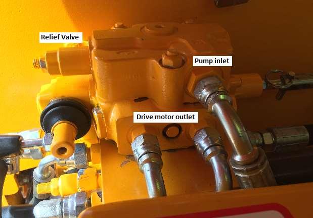
Checking the system pressure
There are two circuits, one for each wheel motor, which have their own pump and relief valve. The following instructions and illustrations describe the LH wheel motor circuit, but this procedure will need to be performed on both circuits.
The Relief valve for the RH wheel motor circuit is located on the lower end of the control valve assembly, while the gauge must be connected to the adjacent work section.
Use the chart below to determine the correct operating pressure for your machine. The displacement of the wheel motors fitted to the machine by referring to the model number code.
Alternatively, later model machines have a two digit dash number stamped along side the inlet port of the control valve section. This represents the system pressure of the machine in hundreds of psi. (e.g. 25 = 2500psi). Increasing the pressure above these ratings will reduce the life of the wheel motors.
To check, proceed as follows:
Take a suitable gauge which is calibrated to 5000+ psi. connected to a short hose with a 9/16 Female JIC Swivel nut fitting.
Remove the front drive motor outlet hose from the top wheel section and connect the gauge. Blank the hose removed (9/16 JIC male blank)
Disengage the Free Wheeling Hub (FWH) pins.
Start the engine and bring it to 2/3 throttle, and operate the spool with either the pedal or hand control in the correct direction. If necessary, the Relief valve should be adjusted to achieve the pressure required.
Repeat the procedure to the lower relief valve.
If it is not possible to achieve these pressures, the problem could be with the hydraulic pump, spool check valves, or the relief valve cartridge.


