
Hydralada POWER BEYOND Kit Installation.
Walvoil Collector Block Machines 2015 Onwards.
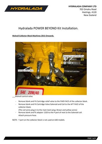
Walvoil control valve
- Remove blank and Fit Cartridge relief valve to the FWD FACE of the collector block.
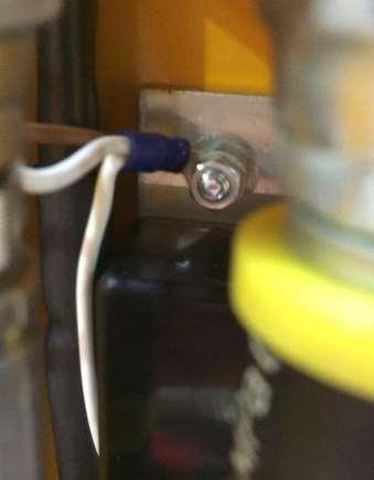
- Remove blank and Fit Cartridge Valve Solenoid and Coil to the AFT FACE of the collector block.
(The coil wires plug in to the main loom plug. Brown and yellow wires)
- Remove blank and fit adapter 1320 to the P port of next to the Solenoid coil. Attach pressure hose.
NOTE: T port on the collector block is not used on 640 models.
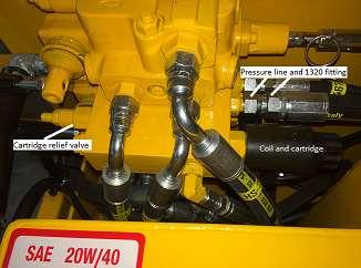
Aux oil tank return to the hydraulic filter
Return hose to filter head
Return hose
- Remove straight through connection on the filter housing
- Install fitting 1738 to the filter housing. Attach T fitting 7343 and attach existing hose.
- Attach hose end fitting 7344 to the 5/8inch Return hose and attach to lower T fitting.
- Route return hose down under the collector block. Route both hoses up the boom following the control cables to the cage.
Remove cage cover from the lower rear of the cage. Before connecting the hydraulic hoses mount the aux oil module,.
- On the rear face of the cage below the hose mount block
- Paint strip the area around the mount pole to give a good earth.
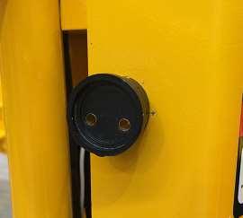
- Attach AUX OIL MODULE 1680 and the two earth wires for the plug and aux switch.
- Plug the Aux oil module into the cage boom loom and attach to the aux switch. The Boom loom has the plug already fitted.
NOTE: Both the plug wires should already be fitted, they could be tucked up into the wire sheathing out of the way (extra earth wire has been included in the kit).
NOTE: All hydraulic connections should have Loctite sealant or thread tape on the threads
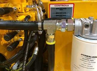
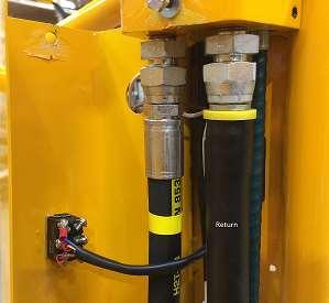
- Fit adapters 7345 to the lower face of the hose mounting block
- Connect pressure hose to the LH adapter (looking rear from the front)
- Attach push on adapter 7344 to end of the Return hose. Connect return hose to the RH adapter.
- Fit two adapter bungs fit to upper surface. (Unless the fitting attachments are available)
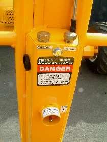
- Fit switch guard to outer side of the lower cage cover (already removed) The Aux switch guard can be added as a piece of pipe welded on to provide protection (not included in the kit.) Aux switch and Hydraloppa plug holes should already be drilled into the cover.
- Weld and paint.
- Fit aux oil switch (spring centered) to the cage cover. Attach wires; Blue top, yellow middle, brown bottom.
Note: The wires on the aux oil switch should be attached so that they are on the Return hose side, as the pressure hose pulses in use and will chaff.
- Run wires through hole in cover
- Plug brown wire goes to the Lower LH terminal. (Looking as seen here)
- Fit Decals 61-5240-00 DANGER, AUX OIL & 61-7366-00 AUXILIARY OIL ON/OFF