


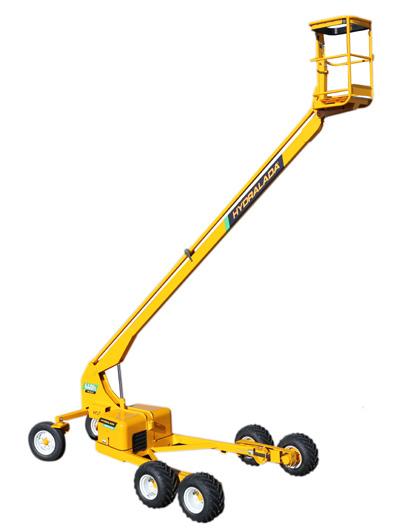
Hydralada Mobile Elevated Working Platforms (MEWP) is boom type work platform built to conform to AS/NZS 1418.10: 2011 Mobile Elevatying Work Platforms. The safe use and inspection requirements for Hydralada MEWP conform with AS 2550.10—2006 Cranes, hoists and winches—Safe use Part 10: Mobile elevating work platforms. The purpose of this inspection booklet is to keep the Hydralada MEWP in proper safe working condition and to detect any signs of malfunction at the earliest possible time. Defective parts and/or equipment malfunctions jeopardise the safety of the operator and other personnel, along with the risk to cause damage to the MEWP. Do not attempt to make repairs unless you are authorised to do so.
Safety procedures for maintenance.
Every person who maintains, inspects, tests, or repairs these MEWP’s, and every person supervising any of these functions, MUST be properly trained. This leaflet provides the inspection procedures and routine maintenance that will help you keep the Hydralada MEWP in good operating condition.
DO NOT perform other maintenance unless you are a TRAINED mechanic, QUALIFIED to work on the Hydralada MEWP. Contact QUALIFIED maintenance personnel if you find problems or malfunctions. Information contained in this manual concerns only current Hydralada Elevating Work Platforms, and Hydralada Company reserve the right to make changes at any time without obligation. An individual risk assessment must be carried out prior to any work or task being preformed.
A competent person is a person who has acquired, through education, training, qualification or experience or a combination of these, the knowledge and skill enabling that person to preform the task required.
References:
New Zealand
• Health and Safety at Work Act 2015
• Best Practice Guidelines: Mobile Elevating Work Platforms
• Best Practice Guidelines: Safe Use of Elevating Work Platforms in the Horticultural Industry
• AS/NZS 1418.10: 2011 Mobile Work Platforms
• AS 2550 Part 10 Safe Use of Mobile Work Platforms
Australia
• Commonwealth HSE Legislation.
• Individual State HSE Legislation.
• AS/NZS 1418 Part 10. Mobile Work Platforms
• AS 2550 Part 10. Safe use of Mobile Work Platforms.
International Standards
• ISO 16368 Mobile Work Platforms
• ISO 16653 Part 3 Mobile Work Platforms for Orchard operations.
• ISO 18893 Safe use of Mobile Work Platforms.
Inspections required to be carried out are in the 4 following categories.
Completed daily by the operator at the start of each shift (8 hours)
The operator or competent person must: Record the inspection in the machine’s logbook along with any defects, bring any faults to the employer’s or principal’s notice, to ensure that these are fixed before the work platform is used again.
Completed monthly or every 200 hours the inspection must be carried out by a competent person or a person certified by the manufacturer.
The owner or delegated competent person must record the results of any inspection along with any defects in the machine’s logbook. Ensure that any faults are corrected before the machine is returned to service.
Completed every 6 month Industrial models and machines outside New Zealand. Completed every 12 Monthly on Horticultural models within New Zealand.
Periodic safety inspections must be carried out by a competent person, or a person certified by, or supervised by, the manufacturer. The competent person must record the inspection and any defects found in the machines logbook or file records. Any faults discovered must be corrected before the machine is returned to service.
In addition to the previous inspections, MEWPs should have a major inspection that have been in service for 10 years, or after an accident or modification. The major inspection must be carried out by a competent person experienced in the servicing of MEWPs, or a person certified by, or supervised by, the manufacturer. This check must be recorded in the log book or file records of the MEWP and be signed off by the competent person as per AS 2550.10 section 6.4.5.

Regulations for MEWP inspections do vary depending on the country or state that the machine is operated in. For additional information or clarification is required contact your local Hydralada dealer or Hydralada Company. Once your inspection is completed, fill in the MEWP Log Book, taking care to record any matters which may need further attention. Any defects identified are to be recorded in the faults section of the log book. Any faults discovered must be corrected before the machine is returned to service.
inspect level, ensure boom is fully lowered. 6
Inspect the machine log book, confirm no active faults in the fault log.
Check the operating hours to confirm the current service period. If the MEWP has turned into another 100 hour period it must be serviced as shown on the service check sheet.
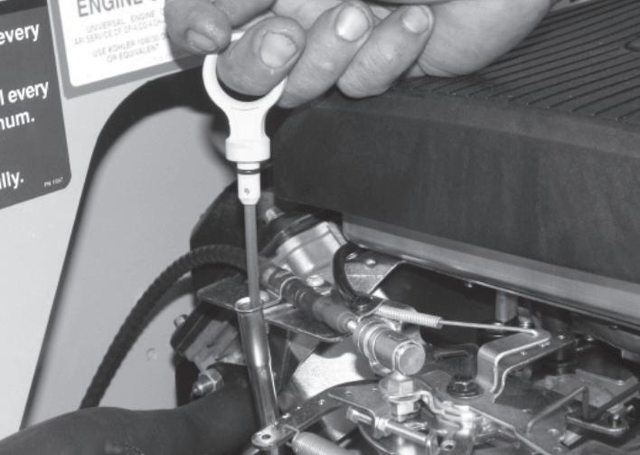
With the engine turned off, remove the dipstick located on the top rear of the engine, and wipe the oil off. Re-insert the dipstick into the tube, and remove again to check the level. If the level is low, fill to the “F” mark with the recommended oil. Ensure that the level always remains within the operating range on the dipstick.
Check the fuel gauge to see that the fuel tank is full. Check to see that the tank cap is in place and is tight. Visually inspect that there are no defects in the sealing surfaces of the Fuel Tank Cap. Inspect around fuel tank for evidence of fuel leaks.
To check the hydraulic oil level the boom must be completely lowered and the engine turned off. Oil must be added to the system if the level is not clearly visible in the filler neck.
The minimum hydraulic oil level is 70mm from the top of the internal screen and the maximum is 50mm from the top of the internal screen. If it is necessary to add hydraulic oil, refer to the ‘Specifications’ chapter of this manual for type and grade of hydraulic oil. Remove the quarter turn filler cap, and add oil until the reservoir
reaches the correct level.
Hydraulic oil leaks are easily visible and can show up any place. Visually inspect the entire MEWP for hydraulic oil leaks. Check the ground under the MEWP for leaked oil. Carefully inspect the exposed hydraulic hoses for signs of leaking hydraulic oil or obviously loose fittings.
Inspect tyre condition, check pressures. 26x12x12 drive tyres must be water filler for stability ballast.
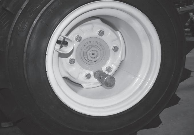
Inspect wheel rims and for loose wheel nuts. Inspect hub nuts for indication of movement.
Rubber track model, inspect rubber track sprockets and rollers are running in the track drive groove.
Visually inspect the entire MEWP for deformity, cracks, dents or anything unusual.
Inspect for cracks or damage. Clean the Work Platform daily before beginning operations.
Pivot pins are secured with retaining bolt on welded ear and a secondary circlip. Ensure all retaining bolts and circlips are in place on each pin to prevent the pin from
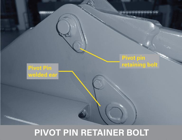
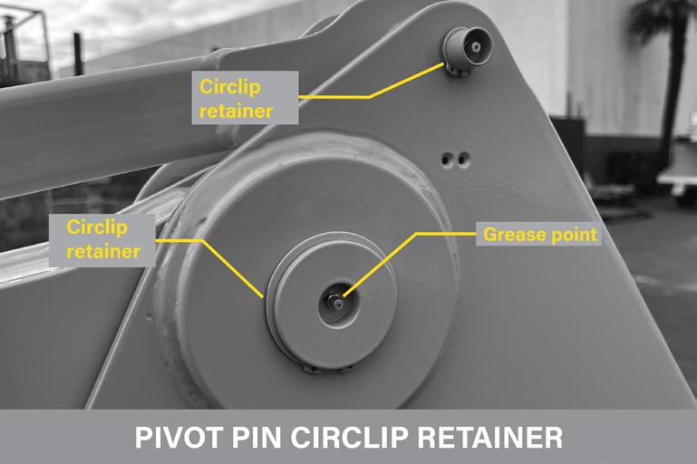
coming out of position.
Top Ram Pin on Compact have a roll pin. Missing Bolts or Circlips must be replaced.
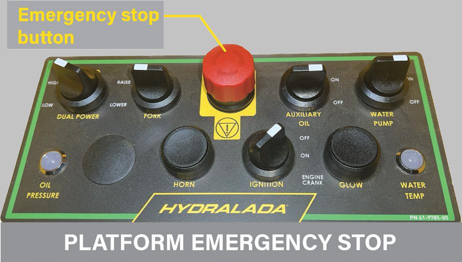
Reset the emergency stop buttons on the Ground station and Work platform control stations.
Turn Ignition switch to on and the inclinometer Alarm will sound one beep. Indicating system power is active. Push in Platform Workstation Emergency stop button, push starter, no action system power has been removed. Reset button.
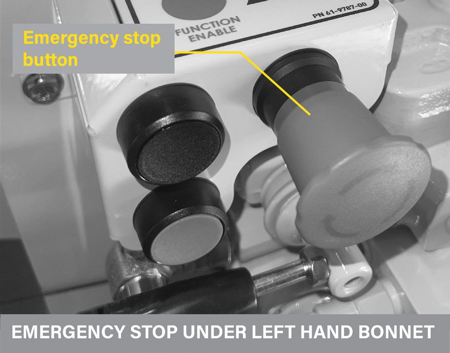
Push in Ground station Emergency stop button, push engine crank, no action, system power has been removed.
Hydralada Elevating Work Platforms are fitted with Alarms which become active once the MEWP reaches its maximum slope rating.
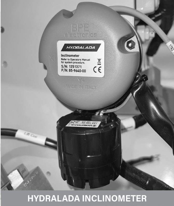
To check the operation, proceed as follows; • Turn system power on. The inclinometer will do a selftest and sound an audible beep indicating the system is active and ready.
Check operation of the rotating beacon when the ignition switch is turned on.
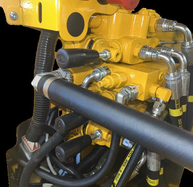
Check the manual movements levers at the control valve to confirm manual operation and lowering function.
"Switched Mid-rail Check the operation of the mid-rail to ensure it is not bent or distorted in any way. Once the midrail is lifted from its operating position, the engine should not run, and the starter should be deactivated. Mid-rail arm should drop to lowered position if not held open.
Visually check the lanyard anchor points to see that they are not deformed, damaged or cut off.
15.
Visually inspect the condition of lanyards and safety harnesses for any, fraying, cuts or damage.
16.
Check operation of the drive controls. Check operation of the pin brakes. Test the Speed functions are working correctly.
17.
With system power on, test operation of the horn.
INSPECTION
OPERATORS DAILY CHECKS
1 BATTERY AND CABLES
2 WHEEL RIM NUTS
3 DRIVE WHEEL AXLES NUTS
4 DRIVE WHEEL FREE WHEELING HUB PINS
5 CASTOR LEG BEARINGS AND PIVOTS
6 RUBBER TRACK TENSIONS
DESCRIPTION
As per previous page
Visual inspect cables tight and for damage
Check torque wheel nuts
Visual inspect hub nut for movement
Actuate and inspect for proper operation
Check bearings and leg pivot
Visual Track tension and rollers.
ANY SAFETY RELATED FAULTS MUST BE REPORTED AND CORRECTED IMMEDIATELY, OR THE MEWP WITHDRAWN FROM SERVICE
Carry out operators’ daily checks, confirm in logbook that checks are being carried out and signed.
1. BATTERY AND CABLES
Inspect battery cables are tight, secure and clear of sharp edges or hot surfaces.
Check for chaffing damage and check battery is secured.
2. WHEEL RIM NUTS
Check torque all wheel nuts with 3/4”” Socket to;
60 Ft/Lbs (4 & 5 Stud rims)
85 Ft/Lbs (6 Stud rims)
Wheel nut torques must be adhered to as over tensioning a pressed steel rim can collapse the tapered hole the wheel nut engages into. This condition is irreversible and causes wheel nuts to continually loosen.
3. DRIVE WHEEL AXLES NUTS
Visually inspect the wheel axle hub nut for movement. If movement evident Re torque nut, contact Hydralada service technician.
4. DRIVE WHEEL FREE WHEELING HUB PINS
Check the freewheeling hub pins disengage freely. Check hold in open position, when released they should reengage into the hub. If not remove pin and apply antiseize to pin.
5. CASTOR LEG BEARINGS AND PIVOTS
Jack the tail of the machine clear of the ground, check castor wheel hub bearings for wear or movement. Check hub cap is fitted.
Check for free rotation of the leg on the castor pivot kingpin.
Check for play in the pivot, movement indicates worn bushes.
6. RUBBER TRACK TENSIONS
Inspect rubber track tension and adjust as required. Inspect the track rollers are running centre of track.
Note, this inspection must be carried out by a competent technician, on completion this inspection must be signed for in the machine’s logbook and a report of the inspection handed to the owner.
Note, this inspection must be carried out by a competent technician, on completion this inspection must be signed for in the machine’s logbook and a report of the inspection handed to the owner.
1. INSPECT LOGBOOK, STABILITY CERTIFICATE (LOGBOOK ENTRIES, FAULT
LOG COMPLETED, SERVICING UP TO DATE, INSPECT MACHINE FOR NON STANDARD MODIFICATIONS THAT AFFECT STABILITY)
Logbook, or machines record of maintenance is to be made available at the start of the inspection. This Certificate is provided with every new Hydralada MEWP in the Delivery Manual. If the Stability Certificate is missing, a copy can be obtained from Hydralada Company.
Stability certificate lists the Rated Capacity of the platform, Tyre size and Ballast weight requirement of the Dive wheels, Tyre size and Ballast weight requirement of the Castor wheels, requirement for chassis weights, and the stability rating for the machine’s inclinometer, type of platform and boom fitted and manufacture. If any of these items do not match, then the machine should not be operated. Machines serial decals are located on the rear of the platform, and on the LHS tail for MAXI models and under the engine bonnet for 300 & 360 lists the following information. Serial number, Model number, Year on manufacture, Rated Capacity of the platform, MEWP Mass, Maximum MEWP height from the platform floor, the degree rating of the machine and the height that the inclinometer is armed.
2. GREASE MACHINE
Fully grease machine, investigate any points that do not accept grease.
Test drive both drive directions, lift, lower. Test from platform and from base hand controls. Smooth operation, controls not sticking. Machine drives straight.
4. CHECK EMERGENCY STOP BUTTONS
Reset the emergency stop buttons on the Ground station and Work platform control stations. Turn Ignition switch to on and the inclinometer Alarm will sound one beep. Indicating system power is active. Push in Platform Workstation Emergency stop button, push starter, no action system power has been removed. Reset button.
Push in Ground station Emergency stop button, push engine crank, no action, system power has been removed. (Older models, check operation of Emergency stop switches.)
5. CHECK SPEED CONTROLS
Dual power option
Check speed limiting switch is operating. HIGH speed selected and the boom is in the lowered transport position. Drive machine and select LOW with Platform dash switch. Machine will drop to slower speed. Select HIGH. Raise boom above switch height, machine will be limited to slower speed. Confirm with platform switch. If speed is not limited check switch height setting.
6. CHECK OPERATION OF HILL SIDE RESTRAINT
Operate machine on a slope. The engine at low RPM setting the machine should have controlled decent, in both directions. If one side runs away faster, a defective counterbalance cartridge requires further investigation.
7. CHECK OPERATION OF EMERGENCY
Operate handle for Platform, both engine running and engine OFF
8. CHECK OPERATION OF INCLINOMETER
Hydralada Elevating Work Platforms are fitted with Alarms which become active once the MEWP reaches its maximum slope rating.
To check the operation, proceed as follows.
• Turn system power on. The inclinometer will do a selftest and sound an audible beep indicating the system is active and ready.
9. CHECK OPERATION OF PLATFORM MID RAIL DROP GATE
Switched Mid-rail, Check the operation of the mid-rail to ensure it is not bent or distorted in any way. Once the mid-rail is lifted from its operating position, the engine should not run, and the starter should be deactivated. Mid-rail arm should drop to lowered position automatically if not held open.
10. CHECK ENGINE CRANK BUTTON GROUND STATION
Ground station engine crank should operate with Battery isolator on, and lower e-stop reset ON. Engine will crank not start.
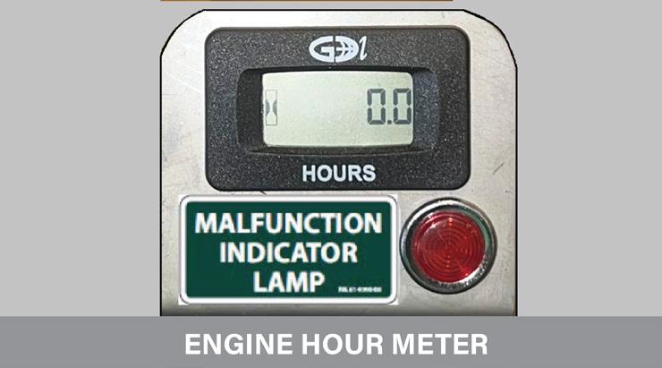
11. CHECK OPERATION OF HOUR METER
Check hour meter is operating. The Hour meter is critical for recording the operating hours of machine and for servicing requirements
Visually inspect the fuel tank and any visible fuel line for damage and leaks.
Inspect the in-line filter which lies on the floor of the MEWP. If there is any visual indication of contamination the filter assembly should be replaced.
Inspect all visible wiring harnesses on the MEWP, for loose connections, broken wires, and frayed insulation. Positive Battery cables must be secure, and cable tied to the battery chassis holder. This prevents cable from chaffing on bell housing and shorting. And damage to positive cable must be replaced.
Remove the caps from the battery and visually check to see that the battery fluid is just covering the separator plates in the cells. The cells can be topped up with distilled water, or a tap with very clean water. (Not required on Maintenance free Batteries)
Remove hydraulic pump bell housing from the engine and inspect the Hydraulic pump couplings, If spider coupling damaged it must be replaced. Drive couplings can have some wear up to 1/3, replace if exceed. Safety feature should the couplings fail, machine will lose hydraulic drive. If oil is present within the bell housing, indication of hydraulic pump shaft or engine crankshaft seals leaking.
16. CHECK TORQUE ENGINE MOUNT BOLTS
Check torque engine mounting bolts, 25 ft/lbs (9/16 Socket)
17. INSPECT HYDRAULIC OIL LEVEL / TYPE
To check the hydraulic oil level the boom must be completely lowered and the engine turned off. Oil must be added to the system if the level is not clearly visible in the filler neck.
The minimum hydraulic oil level is 70mm from the top of the internal screen and the maximum is 50mm from the top of the internal screen. If it is necessary to add hydraulic oil, refer to the ‘Specifications’ chapter of this manual for type and grade of hydraulic oil. Remove the quarter turn filler cap, and add oil until the reservoir reaches the correct level.
18. INSPECT FOR CORROSION ON STRUCTURAL COMPONENTS AND FUEL TANK
Treat all surface corrosion. Corrosion evident under fuel tank requires treatment early. Corrosion on platform vertical tubes is not means to fail, but highly recommend it is removed and treated to prevent further progression.
Structural corrosion report to Hydralada for assessment.
19. INSPECT ALL STRUCTURAL WELDS
Inspect CHASSIS LEGS join to chassis base plate, Wheel
motor mounts, chassis side plates (around lift cylinder opening)
Inspect BOOM side plate welds, Pivot boss welds, inspect boom for straightness
Inspect Levelling bar, inspect all welds, if levelling bar is bent or damages closely inspect pivot pins. Bent levelling bar is evidence that Platform has been exceeding its rated capacity. Inspect PLATFORM
20. INSPECT PIVOT PINS
Inspect each pivot pin. Each Pin should be tightly held in the side plates. Check for movement of pin within the plates.
Grease extruding on outside of side-plates is evident of wear. If pins are showing movement in the side plates, additional collars/replacement of existing collars will be required. If boom or Levelling bar has movement but pin is tight within side-plates, pivot pin bushes will need to be replaced.
Twin castor models, inspect pivot pin, bushes and pivot tube, inspect welds on top of castor leg king pins.
Pivot pins are secured with retaining bolt on welded ear and a secondary circlip. Ensure all retaining bolts are tight and circlips are in place on each pin to prevent the pin from coming out of position.
Top Ram Pin on COMPACT 300, HILIFT 360, MAXI 440/540 have a roll pin to secure the pivot pin. Missing Bolts or Circlips must be replaced. Loose bolts are evidence of pivot pin movement.
Visually inspect the complete castor leg assembly including all welds, the pivot bushes, bearings, axle, hub and kingpin assembly retaining cap screws.
Check torque mounting cap screws 160 ft/lbs
Twin Castor Models, inspect the pivot pin boss welds and kingpin mounts.
Inspect cable operation. Pedals should be able to be operated by hand, have free return to neutral position. Stiff cables must be replaced, these can jam in position, and cause unintentional operation of that function. Check pedal stops and adjust as required, out of adjustment pedal stops risks cable breakage.
Visually check the lanyard anchor point for deformation or damage.
25. INSPECT PLATFORM
Inspect cable guard on bottom of Platform. If not fitted if lowered on to object can cause the pedals to jam or damage cables.
Inspect Floor Mat. Ensure the WORK PLATFORM floor and pedal area is clean. The MEWP should be fitted with
an approved mat in good condition. This is a safety issue for two reasons. It prevents debris from locating under the pedals and interfering with their operation. The mat is marked to indicate the operation and use of the controls.
Replace any damaged safety decals, all decals must be legible and visible.
Check drive wheels are fitted with the inflation tube facing outwards from the machine. Wheels fitted incorrectly can damage the taper for the retaining nut. Inspect the wheel rim, any cracking evident, replace rim. Any damage around the mounting bolt tapers is unrepairable, meaning a new genuine Hydralada wheel rim must be fitted. We do not authorise the fitting of new centres or parts thereof to these rims.
28.
Drive tyres on HI LIFT and MAXI models Hydralada MEWP are water-filled. Twin Castor model MAXI with 185x14 Tyres are foam filled. This is to provide ballast and form vital part of the Elevating Work Platforms stability. If the MEWP is being operated in areas where the daytime temperatures are less than 1C, the ballast liquid will need to include antifreeze. Alternatively, the wheels can be foam filled.
Check each tyre for obvious damage that could cause a blowout.
Check the tyres are in sound condition with the tread in good condition, and no perishing on the sidewalls. Worn tyre tread can increase the risk of the machine sliding when at its maximum slope rating.
The tyres must be mounted on the rims to drive in the forward direction. Ensure they are filled to the required level (weight) with a suitable liquid. Check the pressures using a suitable tyre gauge. The wheel must be positioned with the valve at its highest position.
The recommended pressures are set out in the ‘Specifications’ chapter of the operators manual. If the tires are repaired or serviced in any way, they must be ballasted to reach the tare weight as set out in the ‘Specifications’ chapter 1 of this manual.
Check torque all wheel nuts with 3/4”” Socket to; 60 Ft/Lbs (4 & 5 Stud rims)
85 Ft/Lbs (6 Stud rims)
Wheel nut torques must be adhered to as over tensioning a pressed steel rim can collapse the tapered hole the wheel nut engages into. This condition is irreversible and causes wheel nuts to continually loosen.
Check torque drive wheel hub tensions to the following; COMPACT MODELS Wheel motor - 1 1/4” Axle shaft
Check torque to 300 ft/lbs. Movement evident reset and check torque to 325 ft/lbs. (38mm Socket)
MAXI MODELS Wheel motor - 1 1/2”” Axle shaft
Check torque to 350 ft/lbs. Movement evident reset and torque to 375 ft/lbs. (48mm Socket)
Apply alignment paint line to hub nut and axle, this is a good indicator for movement.
31. INSPECT PARK BRAKE RINGS AND BRAKE PIN OPERATING
Cylinder pin will retract when drive pedal is moved in Either Direction. With Engine off the pin should engage the brake ring.
The brake ring is a sacrificial part and will wear quickly when new when bedding in.
32. INSPECT FWH BEARINGS, INSPECT HUB PIN AND INNER HUB
Check operation of FWH pin, disengage pin. Jack chassis leg until drive wheel is clear from the ground, rotate the wheel and check FWH bearings. Rough bearings should be replaced.
Inspect inner hub drive pin holes, Prolonged use of worn inner hubs with oval holes will cause drive pin to break. Broken FWH pin will result in no braking from Hydraulic system or pin brake.
33. CHECK HORN
Test horn button operates. The horn is a safety feature to warn bystanders and get other operators attention.
Servicing of Hydralada MEWP is on a 3000 hour cycle. Refer the table and carry out the required service for each 100 hour interval. Refer Operators manual for additional service information
1
HYDRALADA COMPANY LTD
702 Omahu Road, 4120 PO Box 352, 4156 Hastings, New Zealand
info@hydralada.com
0064 (0) 6 873 0000
The Hydralada marque is your guarantee of satisfaction, reliability and quality – backed with unsurpassed service and support. We will ensure you thoroughly understand your new equipment to guarantee you always hit the ground running. Our systems are thoroughly researched, tested and proven for safety, reliability, affordability and performance. INDUSTRIAL