Thank you for choosing Hydralada® as your Elevating Work Platform supplier.
The team at Hydralada Company will be working hard to ensure that supplying your new machine is only the beginning of our ongoing commitment to provide service and support. An ever increasing circle of owners rely on our products to provide long and efficient service in many different applications and in various international markets. Hydralada Company have been building this type of machine since 1975, accumulating a wealth of experience. Your new machine has been engineered, using the best available components to ensure it gives a long and trouble free life.
The Occupational Safety and Health Regulations impose a duty on manufacturers and owners to take all reasonable steps to ensure that operators are made aware of potential hazards and the correct operating procedures. We have prepared this manual carefully to provide the information you need to meet your obligations. “Ignorance” is not a defence to legal actions in respect of this law so please ensure that you, and your operators study and understand this information before using your Elevating Work Platform (EWP).
The Hydralada Elevating Work Platform has been manufactured specifically for a particular country and complies with the regulations that applied in that country at the time of production. Hydralada Company cannot be held responsible if the Hydralada EWP does not comply with or only partly complies with the relevant legal requirements in other countries and continents.
To ensure the best possible performance, it is important your EWP is serviced and maintained in good working condition. The service section of this manual has been prepared to give those persons responsible for this work the information they require to perform this work effectively. Our Service Department is always available to provide advice of a more detailed nature should this be required.
Finally, DO NOT file this manual away in a dusty corner. This manual should be in regular use, especially with regard to the Daily Inspection and Maintenance section. Should you have any problems or require any further advice please contact your local dealer or Hydralada Company - we will be pleased to assist you.
HYDRALADA® is a registered trademark of AJ & JP Smith Ltd
THE HYDRALADA STANDARD WARRANTY
Hydralada® warrants the new machine referred to on the “Delivery and Warranty Registration” form against faulty parts or workmanship for a period of six months from delivery to the original purchaser.
Where a customer believes a warranty claim may be involved the EWP must be returned to the authorised dealers workshop for assessment. If the owner requires a serviceman to travel to an EWP for diagnosis or repairs, any labour or travelling cost incurred must be met in full by the owner.
Where repairs have been made or attempted to be made to this EWP by anyone who is not an authorised service agent, any application for warranty may be declined.
Any components deemed in Hydralada Company’s opinion to be defective will be repaired or a replacement supplied at no charge to the purchaser, such action being entirely at the discretion of Hydralada Company or its authorised representative. For any claim to be considered evidence that the scheduled servicing has been maintained may be required.
Hydralada Company retain the right to require any part claimed defective to be returned for inspection before any decision or action if any will be undertaken. In any case where Hydralada Company or its dealer may agree that it is impracticable to return any defective components, all failed parts must be tagged and held by the dealer until any decisions are confirmed.
Where a claim is to be made for labour of any kind, detailed instructions and approval to carry them out must be first obtained from an authorised representative of Hydralada Company before any repair or replacement is effected.
This warranty does not extend to cover normal maintenance, or the replacement of normally wearing or expendable parts. Fuel related failures, those which result from poor lubrication of any kind, faults due to misuse, neglect, accident, or unauthorised modification, repair, or attachments incorrectly fitted to the EWP will not be considered.
This warranty may include an extended drive train warranty. COMPONENTS: engine, hydraulic pump, valves and wheel motors are covered against major structural failure, excluding seals and gaskets.
In purchasing this Hydralada Elevating Work Platform with this warranty provided by Hydralada Company the purchaser accepts full responsibility to pay for mileage, transport or any other consequential cost, damages or losses incurred.
This warranty is transferable to a new owner at Hydralada Company’s discretion provided the details of the new owner are advised in writing within seven days of the transaction.
THE HYDRALADA ELEVATING WORK PLATFORM IS NOT ELECTRICALLY INSULATED
If the Work Platform, booms, or any other conductive part of a Hydralada Elevating Work Platform (EWP) contacts a high-voltage electrical conductor, the result can be SERIOUS INJURY or DEATH for persons on or near the EWP.
STOP DAN G E R
GO NO CLOSER THAN MINIMUM SAFE APPROACH DISTANCES (M.S.A.D).
The M.S.A.D. in most areas of New Zealand is 4.00 Metres for overhead power lines on poles and 8.00 Metres for overhead power lines on towers.
You must check with your local power authority to obtain the correct M.S.A.D. for your area.
Be sure to allow for sag and sway in the wires and the Work Platform, and regard all conductors as energised at all times.
If a Hydralada EWP comes in contact with a live electrical conductor, the entire machine can be charged.
If that happens, you should remain on the EWP and not contact any other structure or object within reach. That includes the ground, adjacent buildings, poles, and any object not a part of the Hydralada EWP. Such contact could make your body a conductor to the other object creating an electrical shock hazard resulting in SERIOUS INJURY or DEATH.
DO NOT attempt to enter or leave the Hydralada EWP until you are sure the electricity has been turned off.
If a Hydralada EWP is in contact with a live conductor, the platform operator MUST warn others on the ground in the vicinity of the Hydralada EWP to STAY AWAY from the machine, since their bodies can also form a path for electricity to ground thus creating an electrical shock hazard with possible ELECTROCUTION and DEATH.
DO NOT attempt to operate the Hydralada ground controls when the platform, booms, or any other conducting part of a Hydralada EWP is in contact with electrical wires or if there is an immediate danger of such contact.
Personnel working on or near a Hydralada EWP must be continuously aware of electrical hazards, recognising that SERIOUS INJURY or DEATH can result if contact with an electrical wire does occur.
Table of Contents
Introduction
n Signs
n Qualified Operators
n Intended use
n Operational Rules
n Maintenance
n Handing
n Responsibilities of Parties
n Options
n Other HYDRALADA Equipment
n HYDRALADA Model Code Key viii
n Identifying the EWP (Elevating Work Platform) viii
n Identifying the Engine
n Additional Information
1. Specifications
n Specifications of the Hydralada EWP (Elevating Work
n
n
n
n
2. Safety
n
3. Safety Devices
n
4. Controls
n
Table of Contents
5. Daily Inspection and Maintenance n
6. Operation
9. Options
10. Troubleshooting o
Table of Contents
o Engine Fault Diagnosis Flow Chart 10-1
o Electrical Fault Diagnostic Flow Chart (Kohler Engine) 10-2
o Hydraulic Fault Diagnostic Flow Chart 10-3
11. Servicing
o Engine Identification Numbers
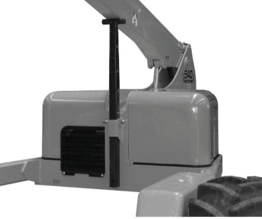
o Boom Support
o Recommended Lubricants 11-1
o Grease
o Engine Oil
o Engine Oil Type
o Checking the Engine Oil Level
o Changing the Engine Oil
o Changing the Engine Oil Filter
o Air Cleaner and Pre-cleaner Element 11-3
o Servicing the Pre-Cleaner 11-3
o Servicing the Paper Element 11-4
o Air Intake/Cooling Areas 11-4
o Starter Motor 11-4
o Ignition System 11-4
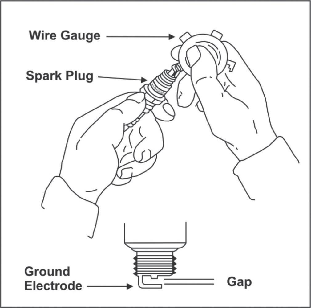
o Check Spark Plugs 11-4
o Fuel Recommendations
o
o
o
o
n The Chassis
o Cable Tray
o Pedals
o Pedal Stops
o Pedal Stop Adjustment - Drive Wheels 11-7
o Pedal Stop Adjustment - Boom Lift 11-7
o Wheel Nuts 11-7
o Tyres 11-8
o Pivot Points
o Braking Systems
o Hour Meter
o Hydraulic Oil Filter
12. Firefighting
n Hazardous Components 12-1
o Battery, Lead/Acid (UN 2794) 12-1
o Diesel Fuel (NA 1993) 12-1
o Gasoline (UN 1203) 12-2
o Hydraulic Oil (UN 1270) 12-2
o Liquefied Petroleum Gas (UN 1075) 12-3
o Motor Oil (UN 1270) 12-3
13. Alphabetical Index
Introduction
The most important chapter in this manual is “Safety” chapter 1. Take time, now, to study it closely. The information in chapter 1 may save your life, or prevent serious injury to yourself or others.
n Signs
The following six conventions are used throughout this manual.
The Danger sign shown below.
DAN G E R
The signal word Danger indicates an imminently hazardous situation which, if not avoided, will result in death or serious injury.
The Warning sign shown below.
WARNING
The signal word Warning indicates a Hazard which has the potential to result in death or serious injury.
The Caution sign shown below.
CAUTION
The signal word Caution indicates;
1. A potentially hazardous situation which, if not avoided, may result in minor or moderate injury
2. An action, about to be performed, can harm the EWP if not done correctly.
The Note sign shown below.
NOTE
This NOTE sign means that the information following is to assist you in either the proper steps to take for an action or as additional information concerning your present situation, but does not indicate a dangerous condition to either you or the EWP.
The Hot Tip sign shown below.
This HOT TIP sign is provided to give you helpful information on various aspects of operating the Hydralada EWP. This information is based on actual operator experiences over many years of operational use and will make operation of your Hydralada EWP more efficient.
The Important sign shown below.
IMPORTANT
This IMPORTANT sign is similar to the note sign but implies a greater emphasis on the importance of the information following. The information is to assist you in either the proper steps to take for an action or as additional information concerning your present situation, but does not indicate a dangerous condition to either you or the Hydralada EWP.
n Other Publications
1. This Operators Manual contains the generic information you require to operate your EWP efficiently and safely, and is one of three Manuals delivered with each Hydralada EWP.
2. Delivery Manual (PN 64-5014-00)
This Manual contains the information unique to each individual EWP and includes:
• Certificate of Stability
• Warranty Registration form
• Acknowledgement of Safety Responsibility form
• Dealer Pre-Delivery check
• 250 Hour Service form
3. Log Book (PN 64-5015-00)
This Book provides a convenient format for Owners and Operators to record relevant information regarding the Elevating Work Platform’s operation and servicing.
n Qualified
Operators
The Hydralada Elevating Work Platform has built in safety features and has been factory tested for compliance with Hydralada specifications and Industry standards. However, any personnel lifting device has the potential to be dangerous in the hands of untrained or careless operators.
Introduction
Training is vitally important and MUST be done under the direction of a QUALIFIED person.
The operator must display a sound understanding of the safe operating parameters of the Hydralada EWP as well as displaying proficiency in handling and operating the Hydralada EWP.
Before beginning operation of the Hydralada EWP the operator must read and understand the operating instructions in this manual, as well as the decals, warnings, and instructions on the EWP itself.
Before operating the Hydralada EWP you must be AUTHORISED by the person in charge to do so.
n Operational Rules
The following rules will help ensure the safety of personnel and help prevent needless downtime and damaged equipment.
1. Only TRAINED and AUTHORISED operators shall be permitted to operate the equipment.
2. All manufacturer‘s operating instructions and safety rules, must be strictly adhered to.
3. All employers‘ safety rules along with all OSHA and other Government safety rules must be strictly adhered to.
4. Repairs and adjustments shall be made only by QUALIFIED TRAINED maintenance personnel.
5. No modification shall be made to the equipment without prior written consent of the Hydralada Engineering Department.
6. You must make a pre-start inspection of the Hydralada EWP at the beginning of each shift. A malfunctioning EWP must not be used.
7. You must make an inspection of the work place to locate possible hazards before operating the Hydralada EWP.
WARNING
DO NOT operate this equipment unless you are TRAINED and AUTHORISED and have read and thoroughly understand all of the information given in this Operator‘s Manual and on all DANGER and CAUTION signs on the EWP. Misuse of this EWP can result in DEATH or SERIOUS INJURY.
n Maintenance
Every person who maintains, inspects, tests, or repairs these Elevating Work Platforms, and every person supervising any of these functions, MUST be properly trained. This Operator‘s Manual provides a daily inspection procedure that will help you keep your Hydralada EWP in good operating condition.
DO NOT perform other maintenance unless you are a TRAINED mechanic, QUALIFIED to work on the Hydralada EWP. Call QUALIFIED maintenance personnel if you find problems or malfunctions. Information contained in this manual concerns only current Hydralada Elevating Work Platforms, and Hydralada Company reserve the right to make changes at any time without obligation
n Handing
When describing locations on the EWP, it is always considered the operator is standing in the Work Platform with their back to the engine and the castor wheel behind. See chapter 1 page 1-4 to 1-9.
n Responsibilities of Parties
This Operators Manual has been prepared to enable the Operator to operate and carry out routine service of the EWP in a competent manner. While aspects of safety are covered throughout the text in this manual, owners and operators also incur responsibilities under Industry and State Standards and Legislation. Some of these documents are: New Zealand
• Health and Safety at Work Act 2015
• Best Practice Guidelines: Mobile Elevating Work Platforms
• Best Practice Guidelines: Safe Use of Elevating Work Platforms in the Horticultural Industry
• AS/NZS 1418.10: 2011
Mobile Work Platforms
• AS 2550 Part 10
Safe Use of Mobile Work Platforms
• NZ Health and Safety in Employment Act 1992 Australia
• Commonwealth HSE Legislation.
• Individual State HSE Legislation.
• AS/NZS 1418 Part 10.
Mobile Work Platforms
• AS 2550 Part 10.
Safe use of Mobile Work Platforms. International Standards
Introduction
• ISO 16368
Mobile Work Platforms
• ISO 16653 Part 3
Mobile Work Platforms for Orchard operations.
• ISO 18893
Safe use of Mobile Work Platforms.
It is imperative that all owners and users of the Hydralada EWP read, understand, and confirm to all applicable regulations. Compliance to OSHA regulations remains the ultimate responsibility of the employer and operator using the equipment.
n Options
The use of optional equipment is discussed throughout the manual as it applies to a particular aspect of operations or controls. However not all optional equipment is covered in this way.
A summary discussion of all the optional equipment is provided in the ‘Options’ Chapter.
If you have any optional equipment installed on your EWP you should read the Options chapter.
n Other HYDRALADA Equipment
¨ Power Pruning Equipment
A wide range of Hydralada Power Pruning equipment, both hydraulic and pneumatic, fully compatible with Hydralada Elevating Work Platforms is available.
This includes Hydraloppa power pruners and hydraulic pruning chainsaws.
Use only the standard pickbag or Hydralada™ attachments. The options you will find discussed there are:
Introduction
n HYDRALADA Model Code Key
These numbers are located on the Serial Number decals placed behind the Work Platform and on the left hand tail area of the EWP.
Record your EWP identification numbers on the identification label below for future reference.
MODEL NUMBER:
SERIAL NUMBER:
MODEL NUMBER
U 2 Letters for Spec Level and Chassis Size
S = Standard C = Compact
E = Econo H = Hi Lift
L = Low Profile M = Maxi
G = High Ground Clearance
T = Tandem
F = Forks
U 3 Digits for Lift Height
U 1 Letter for Boom Type
R = Rigid
S = Slew
T = Telescoping
U 2 Letters for Platform Type and Construction
R = Rigid T = Tubular
S = Slew P = Plastic
U Digit/Letter for Classis Type
3 = Three Wheel Chassis S = Flat Land
4 = Four Wheel Chassis B = Brake
5 = Five Wheel Chassis R = Hillside Restraint
RT = Rubber Track
U 4 Digits for Drive Ratio
2 for pump displacement in c.c.
2 for motor displacement in cu/in
U 1 Letter for Engine
M = Magnum
C = Command
K = Kubota
Y = Yanmar
n Identifying the EWP (Elevating Work Platform)
When ordering parts or servicing your EWP it will be necessary to refer to the:
1. Serial Number
This identifies the individual EWP.
Record your Model and Serial Numbers on the identification label below for future reference.
Note: There is an additional factory production number stamped on the extreme rear of the tail of the EWP. This is only used as an internal purposes during the manufacture of the EWP.
2. Model Number
This is a composite set of numbers which enables the identification of particular features and options on the EWP.
n Identifying the Engine
When ordering parts, or in any communication involving an engine always give the Model, Specification, and Serial Numbers of the engine.
The engine identification numbers appear on the decal (or decals) affixed to the engine shrouding. Include letter suffixes, if there are any.
Record your engine identification numbers on the identification label below for future reference.
MODEL NUMBER:
SPEC NUMBER:
DISPL (CC):
SERIAL NUMBER:
Introduction
n Additional Information
For additional information, on any Hydralada® Elevating Work Platforms or products contact your local dealer or the manufacturer.
HYDRALADA COMPANY LTD
702 Omahu Road Hastings 4120 New Zealand
Postal Address: PO Box 352 Hastings 4156 New Zealand
The design, text, photography and illustrations in this publication remain the sole property of Hydralada Company. All rights are reserved. No part of this publication may be reproduced or transmitted in any form or by any means, electronic or mechanical including photocopying, recording or by any information storage and retrieval system, without the written permission of Hydralada Company.
1. Specifications
n Specifications of the Hydralada EWP (Elevating Work Platform)
This Chapter provides the basic technical characteristics of the Hydralada work platform. The Hydralada EWP is a boom type Work Platform built to conform to all applicable Standards. All dimensions, weights, and specifications are nominal only. Due to a policy of continual development some specifications may change without prior notice or obligation.
SPECIFICATIONS COMPACT HI LIFT MAXI
Maximum Rated Platform Capacity 1751 kg (385lbs)
Standard Colour Yellow
Maximum Towing Speed (free wheel hubs released) 30kph (20mph)
Maximum Manual Force @ 1.1 Mts above the Platform Floor 200 Newton’s / 20kgs (50 lbs)
Max Permissable Wind Speed 12.50 mts/sec (30mph)
Maximum Wheel Loading 500kg (1102lbs) 1000kg (2204lbs)
Maximum Chassis Inclination Refer to Stability Certificate (See Delivery Manual - Page 5)
Insulation Rating of Standard EWP Non Insulated
Required Tare Weight of Water Filled Wheel Assembly (minimum)
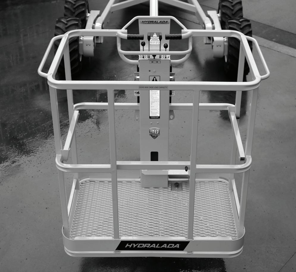
1 Two Man Work Platform Maxi Model - max rated Platform capacity 220 kgs (485lbs).
2 The Hydraulic Oil must contain a Minimum Zinc content of 0.125% by weight (125ppm).
3 Puncture proof - foam filled.
4 In very difficult traction conditions, this pressure can be reduced to 8 psi temporarily. However this practice will cause damage to tyre sidewalls if used for prolonged periods.
1. Specifications
n Engine Data
Engine model1
Engine type
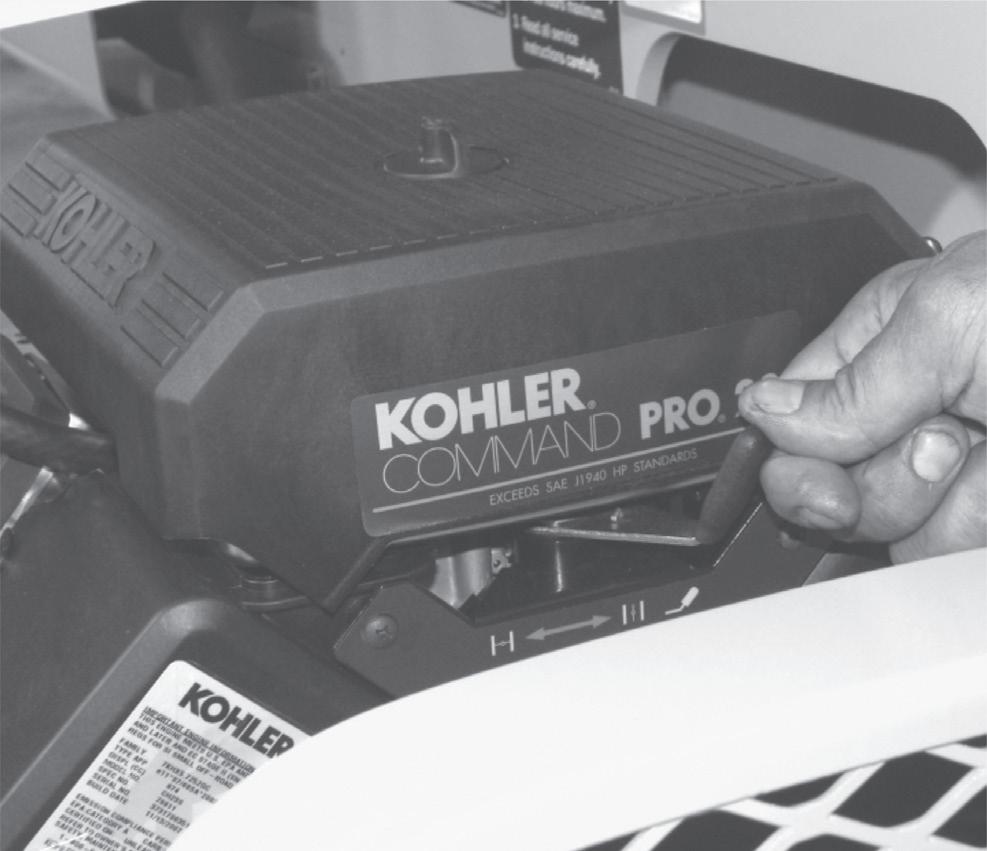
Kubota Z602 Diesel Kohler Command PRO CH680
Twin cylinder, 12 volt, electric start with 40 Amp alternator
Twin cylinder OHV 4 stroke, 12 volt, electric start with 20 Amp alternator
KOHLER Command PRO ECH 730
Twin cylinder OHV 4 stroke, 12 volt, electric start with 25 Amp alternator, EFI
KOHLER Command PRO ECH 630
Twin cylinder OHV 4 stroke, 12 volt electric start with 25 Amp alternator, EFI
1For best results, fill to “F” mark on the dipstick as opposed to adding a given quantity of oil. Always check the level on the dipstick before adding more.
1. Specifications
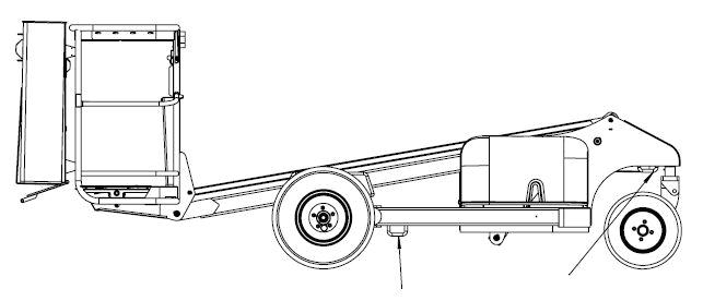
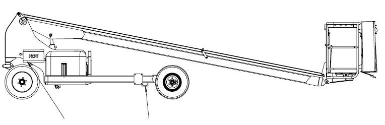
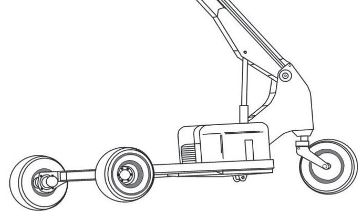
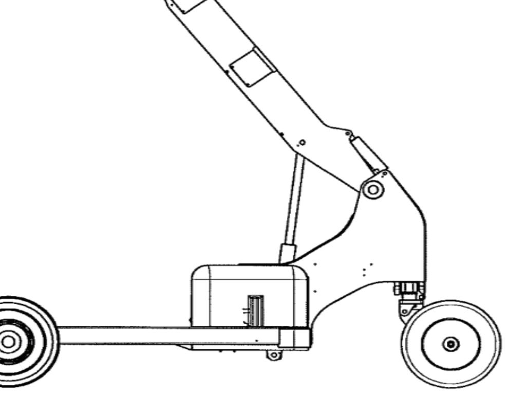
n Nomenclature and Serial Numbers
Left side view of EWP
Right side view of EWP
Platform
Platform Controls
Boom
Drawbar Mount
Battery
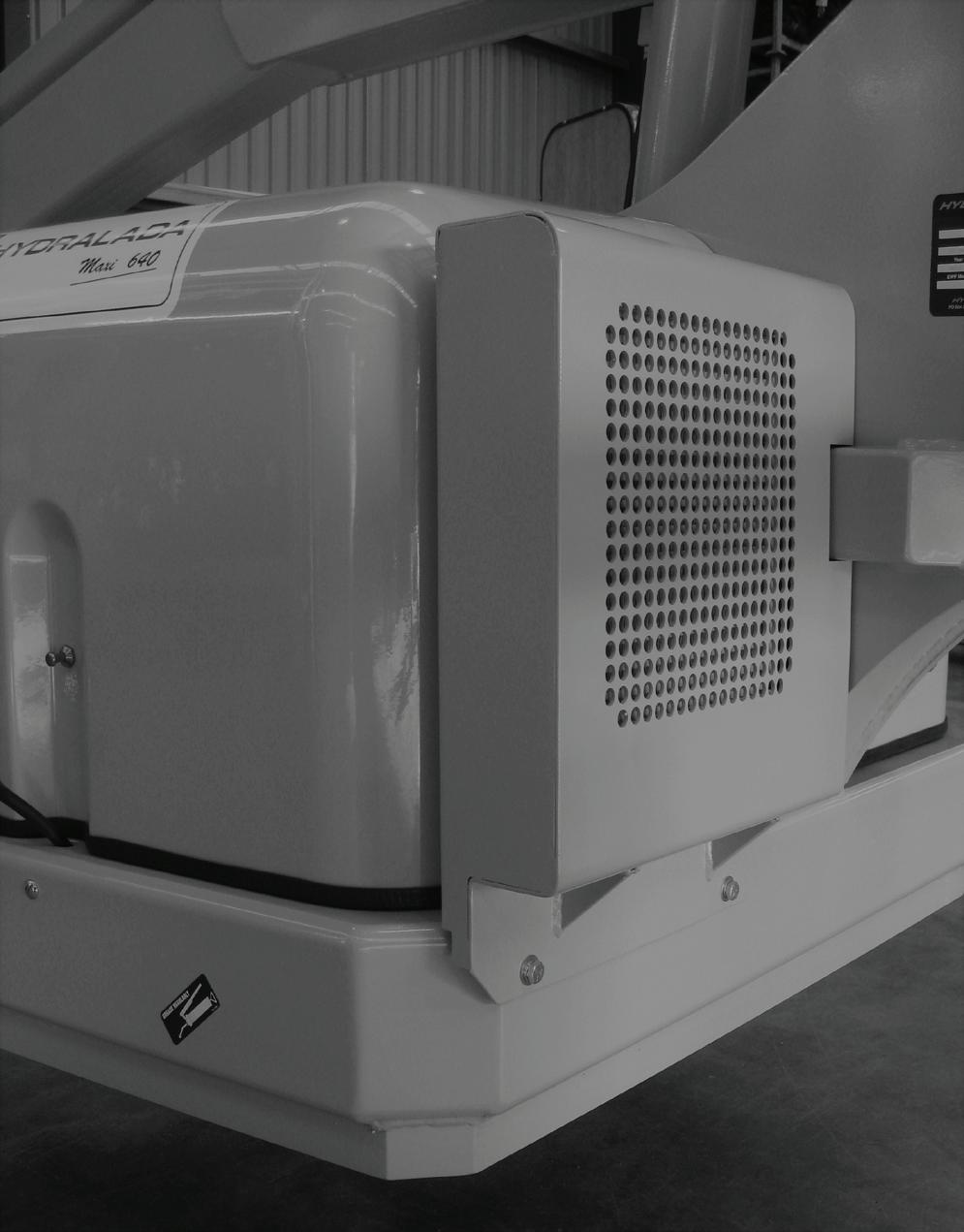
Engine Cover
Pedal Controls
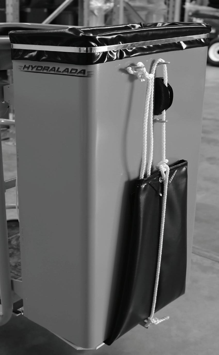
Pick Bag Drive Wheels Serial Number
Castor Wheels Fuel Tank
Hydraulic Oil Tank
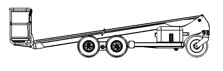
1. Specifications
n Overall Dimensions - Compact 300
COMPACT 300
The dimensions shown below are for the Compact 300 in standard configuration. See ‘Specifications of the Hydralada EWP’ table on page 1 - 1 for detailed dimensions. All dimensions are nominal only.
Base Model 300 GIII 2WD Single castor Kgs 825
Plus add the following amount for the relevant options fitted
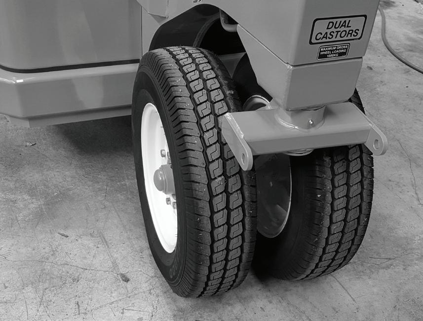
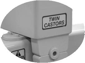
Dual Castor 20
Twin Castor 100
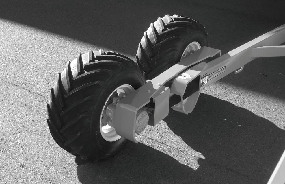
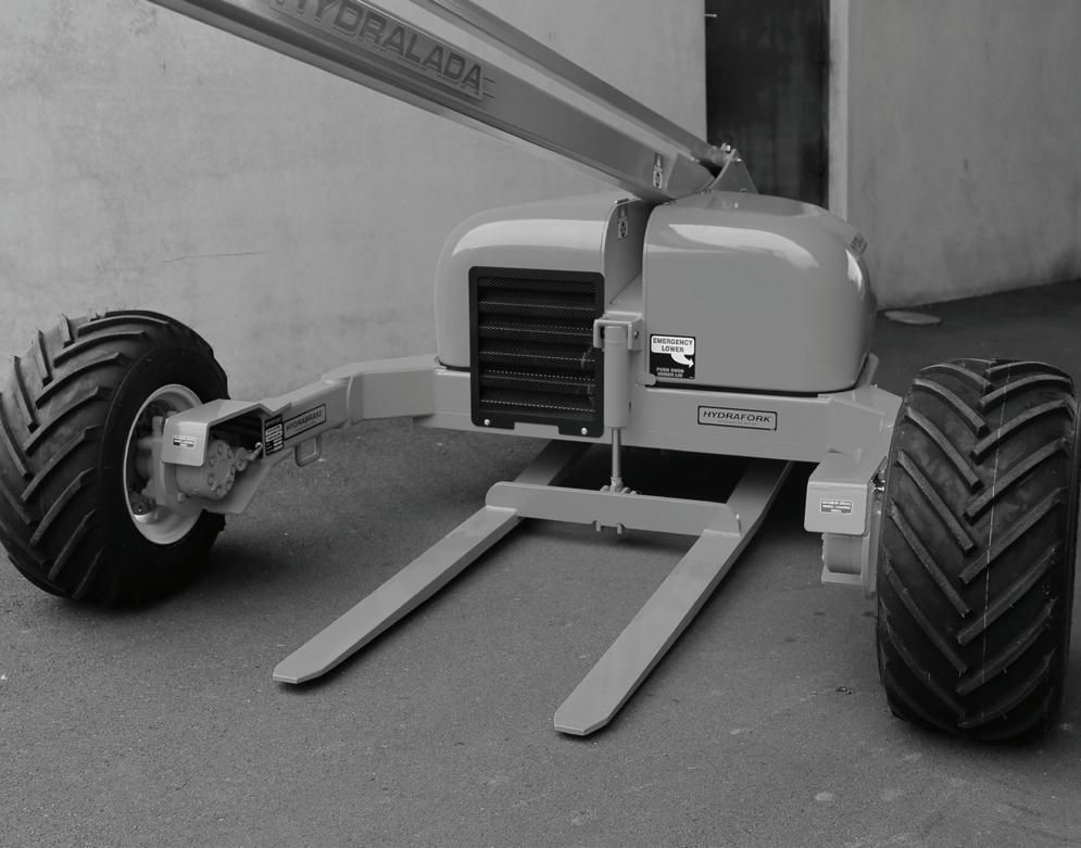
Tandem (4WD) 300/360 300 Hydrafork 150
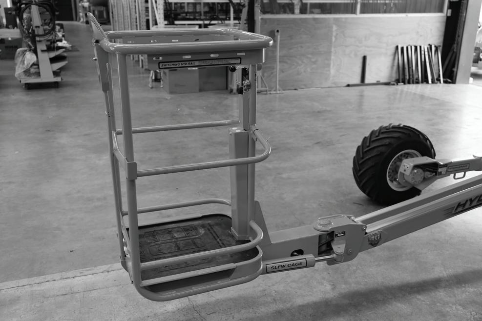
Slew Cage 80
Pick Bag 30
Weights stated are nominal and may vary depending on combinations of options specified. Refer to serial number decal on machine for machine mass
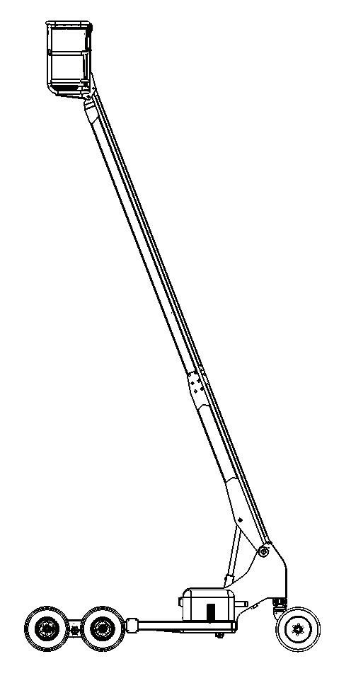
1. Specifications
n Overall Dimensions - Hi Lift 360
The dimensions shown below are for the Hi Lift 360 in standard configuration. See ‘Specifications of the Hydralada EWP’ table on page 1 - 1 for detailed dimensions.
All dimensions are nominal only.
Base Model
360 GIII 2WD Single castor Kgs 950
Plus add the following amount for the relevant options fitted Dual Castor 20 Twin Castor 100 Tandem (4WD) 300/360 300 Hydrafork 150 Slew Cage 80 Pick Bag 30
Weights stated are nominal and may vary depending on combinations of options specified. Refer to serial number decal on machine for machine mass
HI LIFT 360 FORK WIDTH
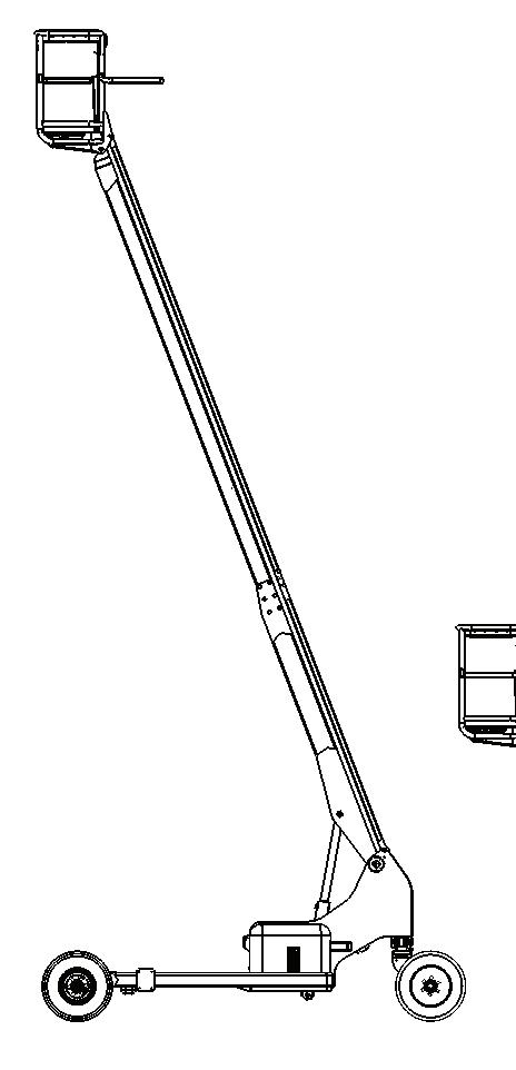
1. Specifications
n Overall Dimensions - Maxi 440
MAXI 440
The dimensions shown below are for the Maxi 440 in standard configuration. See ‘Specifications of the Hydralada EWP’ table on page 1 - 1 for detailed dimensions. All dimensions are nominal only.
Base Model 440 Maxi 2WD Single castor Kgs 1100
Plus add the following amount for the relevant options fitted
Dual Castor 20 Twin Castor 170
Tandem (4WD) Maxi 440 300 Hydrafork 150 Slew Cage 80 Pick Bag 30
Weights stated are nominal and may vary depending on combinations of options specified. Refer to serial number decal on machine for machine mass
TANDEM & 2WD WIDTH
TANDEM
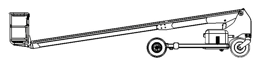
1. Specifications
n Overall Dimensions - Maxi 540
MAXI 540
The dimensions shown below are for the Maxi 540 in standard configuration. See ‘Specifications of the Hydralada EWP’ table on page 1 - 1 for detailed dimensions. All dimensions are nominal only.
Plus add the following amount for the relevant options fitted
Weights stated are nominal and may vary depending on combinations of options specified. Refer to serial number decal on machine for machine mass
TANDEM & 2WD WIDTH
1. Specifications
n Overall Dimensions - Maxi 640
MAXI 640
The dimensions shown below are for the Maxi 640 in standard configuration. See ‘Specifications of the Hydralada EWP’ table on page 1 - 1 for detailed dimensions. All dimensions are nominal only.
Base Model 640 Maxi 2WD Single castor Kgs 1680
Plus add the following amount for the relevant options fitted
Dual Castor 20
Twin Castor 170
Tandem (4WD) Maxi 640/802 50
Rubber Tracks 175
Hydrafork 150
Slew Cage 80
Two Man Cage 80
Pick Bag 30
Weights stated are nominal and may vary depending on combinations of options specified. Refer to serial number decal on machine for machine mass
1. Specifications
n Overall Dimensions - Maxi 750
MAXI 750
The dimensions shown below are for the Maxi 750 in standard configuration. See ‘Specifications of the Hydralada EWP’ table on page 1 - 1 for detailed dimensions. All dimensions are nominal only.
Base Model 750 Maxi 2WD Twin castor Kgs 2200
Plus add the following amount for the relevant options fitted
Tandem (4WD) Maxi 750 100 Pick Bag 30
Weights stated are nominal and may vary depending on combinations of options specified. Refer to serial number decal on machine for machine mass
TANDEM & 2WD WIDTH
1. Specifications
n Overall Dimensions - Maxi 802
MAXI 802
The dimensions shown below are for the Maxi 802 in standard configuration. See ‘Specifications of the Hydralada EWP’ table on page 1 - 1 for detailed dimensions. All dimensions are nominal only.
Weights
2. Safety
n Operating the Hydralada Elevating Work Platform Safely
This Chapter discusses potential hazards which need to be considered when operating the Hydralada EWP. This Safety information is vitally important for the safe operation of a Hydralada EWP.
As with all machinery, the persons working on this platform can be exposed to a certain degree of hazard if these recommendations are disregarded.
The Elevating Work Platforms design is based on recognised International standards which set the parameters of structural strength and stability. Your Hydralada EWP will perform reliably and safely if it is serviced and operated as recommended.
Reading and understanding these safety instructions are an important element of the owners and operators responsibility.
Using the EWP with care, and respecting the safety cautions, will reduce the risk of personal injury and damage to property considerably.
Failure to follow these instructions can result in personal injury or DEATH.
n Workplace Safety Hazards
A Hydralada EWP is an all metal boom, NON-INSULATED Elevating Work Platform (EWP).
Electrocution is likely to occur from the EWP or its operator coming into contact with Electric Power lines. NEVER operate any EWP near any ELECTRICAL conductors.
Regard all conductors as being energized at all times. NEVER operate outside during a thunderstorm. DRIVE carefully to avoid branches protruding into operators platform cage.
Clearance Requirements for Operating NonInsulated Elevating Work Platforms
For Operating Elevating Work Platforms Seeking to Operate in the No GO Zone
1. Notify the power authority before commencing work.
2. Obtain written permission from the power authority.
3. Do NOT commence wrk until a pre-start site/ job meeting and a risk assessment have been completed.
The term “Spotter” is defined as a safety observer who is a person competent for the sole task of observing and warning against unsafe approach to overhead power lines and other electrical apparatus.
Note: These special provisions are not applicable to works in or engaged by compaines in the electricity supply industry.
If the boom is insulated and has a current test certificate issued by a Certified Authority no Spotter is required in the yellow area.
The minimum clearance for overhead power lines on poles is 4.0 metres and for overhead power lines on towers is 8.0 metres. Refer to the below safety decal and before operating the EWP first check with your local power authority.
2. Safety
A suggested safety practice is to have personnel that are familiar with the operation of the emergency controls working in the immediate area of the EWP to assist the platform operator in the event of an emergency.
DAN G E R
Maintain a minimum safe distance to energized power lines. See the “Electrical Hazard” section at the front of this manual for a complete explanation of the hazards concerning electricity.
DAN G E R
READ AND UNDERSTAND ALL OF THESE WARNINGS. MAINTAINING THE STABILITY OF THE EWP IS ABSOLUTELY ESSENTIAL.
Unauthorised Persons in the workplace are a hazard to everyone.
Keep children out of any areas where the EWP is being operated.
Keep ground personnel away from underneath or anywhere near the EWP when the platform is raised.
NEVER permit riders on the EWP at any time.
Watch for bystanders or spectators in the vicinity.
Never allow anyone to be under, or to reach through, the EWP and its equipment while it is in operation.
Hazardous Areas in the Workplace.
Remove all loose objects stored in or on the EWP, particularly in the Work Platform.
Always park the EWP on level ground.
Never operate the EWP while the lighting is inadequate.
Only operate the EWP in areas defined by the supervisor.
Never operate the EWP indoors or in enclosed areas.
It is the responsibility of the operator to ensure that no part of the lifting mechanism comes in contact with branches or other structures which could potentially destabilise the machine.
Eye Injury from flying objects or hazardous materials.
Always wear safety glasses when servicing the EWP.
Always wear appropriate Personal Protective Equipment (PPE) when using saws or pruners.
Keep batteries out of reach of children.
Windy Conditions when operating at elevated sites in exposed conditions.
NEVER operate the Hydralada EWP at high elevations in windy conditions.
NEVER operate the Hydralada EWP in winds or wind gusts of 28mph (12.5 metres per second) or more.
NEVER add anything to the Hydralada EWP that will increase the wind loading (banners, flags, etc).
Flammable Materials or gases associated with fuel and batteries.
DO NOT smoke or permit open flames while fuelling or near fuelling operations.
Store fuel only in approved containers, in well ventilated, unoccupied buildings away from sparks and flames.
Never remove the fuel cap or refuel a gasoline engine while the engine is running or hot.
Never allow fuel to spill on hot machine components.
Maintain control of the fuel filler nozzle when filling the tank.
DO NOT fill the tank to maximum capacity. Allow room for expansion.
Tighten the fuel tank cap securely.
If the fuel cap is lost, replace it with an approved cap from Hydralada Company.
Use of a non-approved cap without proper venting may result in pressurisation of the tank.
Clean up spilled fuel immediately.
Never use fuel for cleaning purposes.
DAN G E R
Gasoline is extremely flammable and its vapours can explode if ignited.
2. Safety
Mechanical Failures as the result of poor or incorrect repair/maintenance/operational procedures.
NEVER operate an EWP that is not functioning properly, or has been damaged, until the EWP has been repaired by a qualified person.
NEVER operate an EWP that does not have all its decals and placards attached and legible.
DO NOT override any of the safety features of the Hydralada EWP.
DO NOT modify the EWP in any way.
NEVER use the EWP as a crane, hoist, or jack.
Never replace electrical fuses with fuses which have a higher rating.
NEVER use the boom for any purpose other than to position personnel, their tools, and materials.
Only attach safety belt lanyard to the lanyard anchor point provided on the platform.
When parts or components are replaced, use only genuine Hydralada replacement parts or components.
DO NOT attempt repairs unless you are a trained and qualified service technician.
Refer to manuals and call experienced repair personnel for help.
Hot Surfaces can cause serious burns. Beware of Hot Exhaust.
DAN G E R
Batteries produce explosive hydrogen gas while being charged. To prevent a fire or explosion, charge batteries only in well ventilated areas. Keep sparks, open flames, and other sources of ignition away from the battery at all times.
Remove all jewellery and wear Personal Protective Equipment (PPE) when servicing or charging batteries.
WARNING
Engine exhaust gases contain poisonous carbon monoxide. Carbon monoxide is odourless, colourless, and can cause death if inhaled. Avoid inhaling exhaust fumes, and never run the engine in a closed building or confined area.
Overhead Obstructions such as branches and other structures.
Be aware of, and avoid overhead obstructions. Always look in the direction of travel when driving. NEVER operate under roofs or in enclosed areas. Always be careful when the Work Platform is elevated.
It is the responsibility of the operator to ensure that no part of the lifting mechanism comes in contact with branches or other structures which could potentially destabilise the machine.
Falling from Heights
Always use a suitable Approved Safety Harness with a short lanyard, connected to the certified anchor point which is provided under the top rail of the Hydralada Work Platform.
The lanyard anchor point is provided for the operator to connect a safety harness to the EWP, and must not be used for any other purpose.
All Work Platform occupants MUST wear and use an Approved Safety Harness.
NEVER permit riders on the Hydralada EWP at any time.
NEVER operate the Hydralada EWP from a position on trucks, trailers, scaffolds, or similar equipment.
NEVER allow the Work Platform to come in contact with another moving, or stationary, Work Platform or any other object.
NEVER use the Work Platform or any part of the extending structure as a crane.
NEVER steady the Work Platform by positioning it against another platform or tree.
NEVER climb onto the Work Platform rail to reach further.
NEVER use ladders, planks, or other devices to extend or increase your work position from the Work Platform.
NEVER jerk the controls. Move the controls slowly and deliberately to avoid jerky and erratic operation. Ensure the EWP is ballasted as described in the stability certificate at all times.
Avoid travelling at speed at higher elevations.
Never engage in any procedure which imposes additional side or wind loads to the work platform.
2. Safety
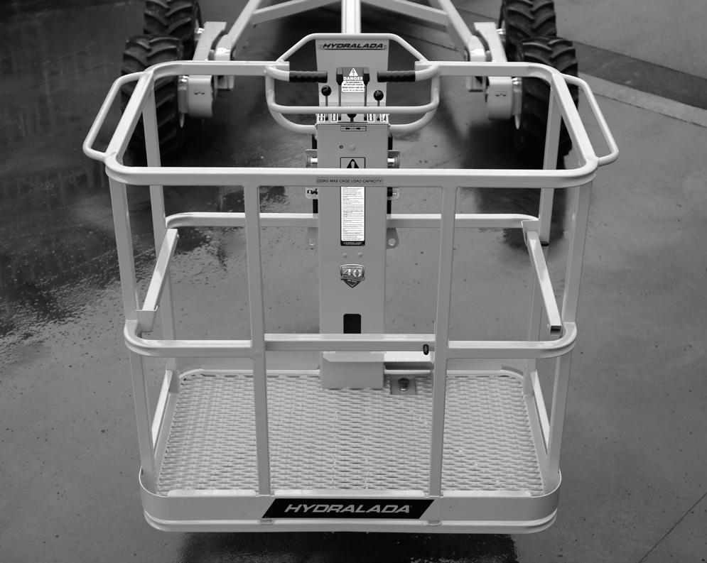
NEVER exceed the Platform Rated Capacity as indicated on the capacity placard at the entrance to the Work Platform.
NEVER operate the EWP when the COMBINED LOAD of the operator, picking bag and its contents, and/or any other items in the Work Platform exceeds the Platform Rated Capacity.
NEVER attempt to enter or leave the Work Platform when it is in an elevated position.
NEVER attempt to transfer from the Work Platform to another structure or vice versa.
Collisions with stationary objects must be avoided.
Always comply with local traffic regulations as they may require.
Take special precautions to avoid any risk of collision when other mobile equipment is in the area. Check the ground conditions and clearance when moving the EWP, to avoid contact with structures or other hazards.
Reduce speed any time the EWP is approaching a stationary object.
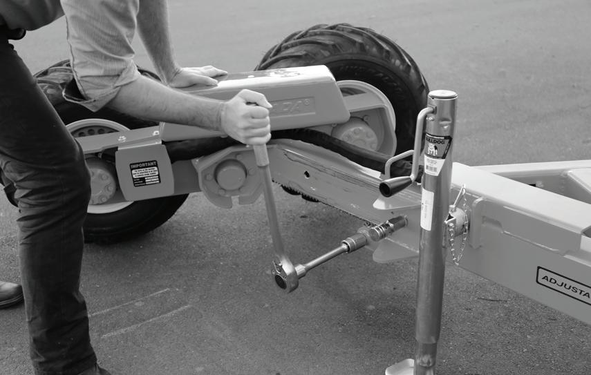
Before towing the EWP check that it is securely coupled to the towing vehicle.
Always make sure the EWP is on level ground and restrained before unhitching from the towing vehicle. NEVER exceed 30kph when towing the EWP.
High Speeds and inappropriately high engine RPM‘s.
NEVER engage in any form of “horseplay” or “stunt driving” while operating the EWP.
NEVER use high engine rpm with the Work Platform at full elevation.
Avoid travelling at speed at higher elevations.
CAUTION
DO NOT operate the Hydralada EWP unless you are trained and authorised, understand the operation characteristics of the EWP, and have inspected and tested all functions to be sure they are in proper working order.
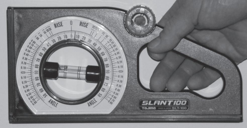
Steep Terrain is always dangerous. Use a proper slope gauge to measure the angle of any inclines before beginning work, and ensure
these are within the allowable incline ratings of your EWP.
NEVER operate the Hydralada EWP on slopes exceeding 5 degrees in either direction unless you have measured the incline and checked the individual EWP Stability Certificate which is included in the machines Delivery Manual.
NEVER move the EWP on steep terrain with the Work Platform at maximum elevation.
Always park on level ground.
Slippery Surfaces or ground conditions can upset the operation of the EWP.
Never operate the EWP on slippery ground.
It is IMPORTANT to ALWAYS keep the platform clean and clear of slippery materials.
Clear away any organic material which accumulates on or within the EWP.
Always maintain a firm footing on the Work Platform floor.
Use a slope meter to establish the gradient of any slopes in the work area, and check that they do not exceed the maximum allowable slopes the Hydralada EWP can work on. This slope angle is listed in the Stability Certificate included in the Delivery Manual.
Instability as the outcome of incorrect loading, or operating procedures.
NEVER operate the EWP when the COMBINED LOAD of the operator, picking bag and its contents, and/or any other items in the Work Platform exceeds the Rated Capacity.
NEVER exceed the platform Rated Capacity as indicated on the placard behind the Work Platform.
NEVER carry loads from any point outside of the Work Platform other than those attachments approved by Hydralada Company.
Ensure the EWP is ballasted as described in the stability certificate at all times.
The tires on this EWP must be water-filled to ensure the Elevating Work Platforms stability.
The Inclinometer and its warning system must be fully operational at all times.
Never allow more than one person in the Single man Platform.
Slewing the Work Platform downhill can result in
2. Safety
instability.
NEVER engage in any procedure which imposes side loads on the Work Platform at higher elevations.
NEVER move the EWP on steep terrain with the Work Platform at maximum elevation.
Always park on level ground.
It is the responsibility of the operator to ensure that no part of the lifting mechanism comes in contact with branches or other structures which could potentially destabilise the machine.
Soft Ground or Mulch under the wheels of the EWP can result in instability.
NEVER raise the boom if the EWP is on soft ground. Operate the boom only on a firm surface capable of withstanding all load forces imposed by the EWP in all operating conditions.
Avoid moving the EWP when you cannot see the ground your wheels are travelling over.
It is preferable that a ground observer be used to ensure that the drive wheels NEVER encounter any obstacles or unforeseen undulations..
WARNING
Hydralada recommend that Operators in a single man platform use an ‘Approved Safety Harness‘ system with a short lanyard.
WARNING
Although the design of the EWP is inherently stable the final overall safety of the operation remains dependent on the operator observing all operation instructions and placards. If there is any doubt, always err on the side of caution.
DAN G E R
DO NOT perform service work under a raised boom unless it is supported by the approved Hydralada service tool.
Failure to comply with this requirement is one of the major hazards of servicing the EWP and can result in SERIOUS INJURY or DEATH.
DAN G E R
The incorrect choice of safety harnesses, belts, and lanyards can be extremely dangerous. Operators MUST have the appropriate training in the use of such equipment.
General
Take care to prevent rope, electric cords, and hoses, etc., from becoming entangled in the Work Platform.
Remove all loose objects stored in or on the EWP, particularly in the Work Platform
In Diesel engines, use the correct fuel grade for the operating season.
Make sure the area below the platform is clear of any personnel before lowering.
CAUTION
Be sure that all the safety decals and placards on the Hydralada EWP are legible. Clean or replace them if you cannot read the words or see the pictures. Clean with soap & water and a soft cloth. Do not use solvents.
You MUST replace a decal or placard if it is damaged, missing, or cannot be read. If it is on a part that is replaced, make sure a new decal or placard is installed on the replaced part. See your Hydralada dealer for new decals and placards.
2. Safety
o Work Place Inspection
Before the Hydralada EWP is used, and during use, check the area in which it is to be used for possible hazards such as, but not limited to:
1. Drop-offs or pot holes.
2. Side slopes and downgrades.
3. Bumps and floor obstructions.
4. Debris.
5. Overhead obstructions including power and telephone lines.
6. Hazardous locations.
7. Inadequate surface and support to withstand all load forces imposed by the elevating Work Platform in all operating configurations.
8. Wind and weather conditions.
9. Presence of unauthorised persons.
10. Other possible unsafe conditions.
3. Safety Devices
n Safety Device Information
This Chapter discusses the Safety Devices of the Hydralada EWP and gives some information on their functions.
The Safety devices listed in this Chapter are fitted to the Hydralada EWP to increase safety in the work place for both the operator and other people near the Hydralada EWP.
For detailed information on the use of these devices, see the ‘Operation’ Chapter of this manual.
WARNING
DO NOT bypass, disable, modify, or ignore any of these devices. Check them carefully at the start of each work shift to see that they are in working order (see “Daily Inspection and Maintenance” chapter 5). If any are found to be defective, remove the EWP from service immediately until a qualified service technician can make repairs.
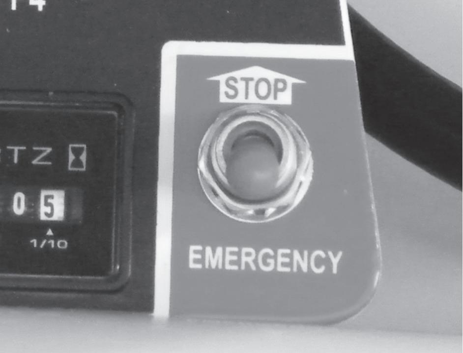
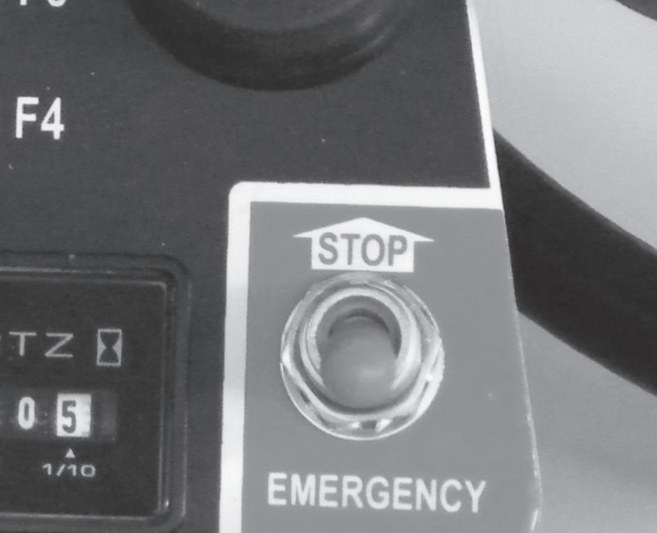
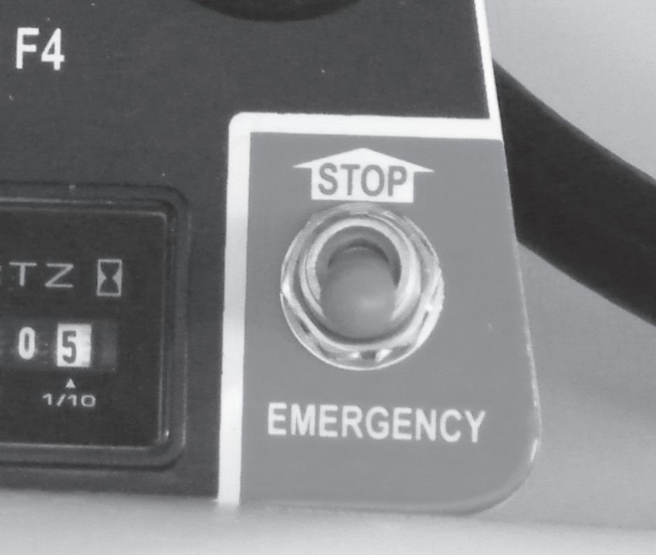
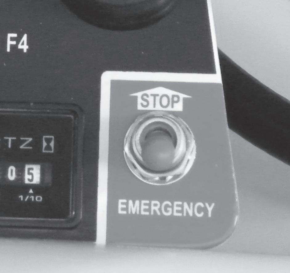
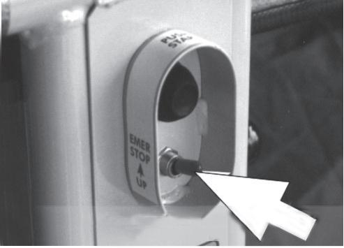
o Emergency Stop Controls
Emergency
Stop at the Base Level
The Emergency Stop function at the Base level of the EWP is provided by the Emergency Stop switch as shown in the picture. This is mounted under the Right Hand bonnet for regular Elevating Work Platforms, or under the Left Hand bonnet for Elevating Work Platforms fitted with Diesel engines.
When this is turned off, the entire EWP is deactivated, and the engine will be shut down.
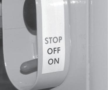
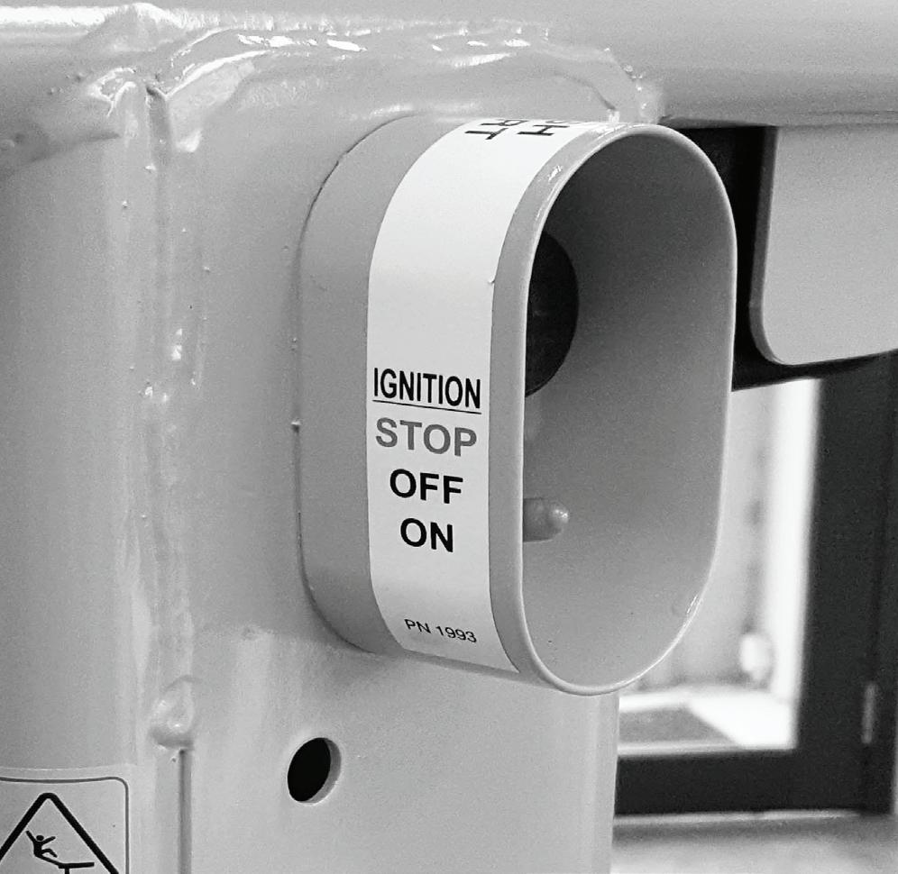
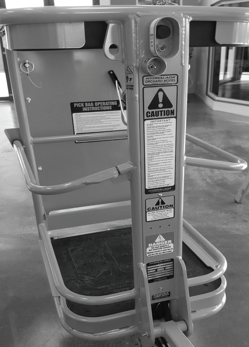
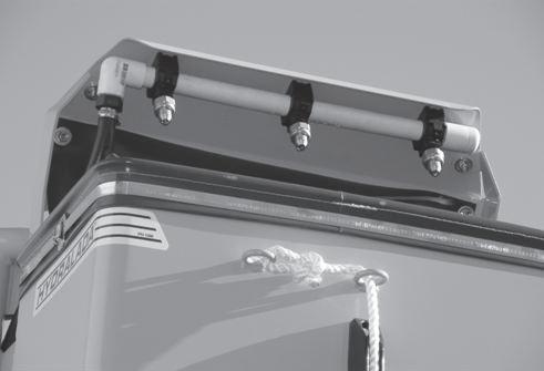
The Emergency Stop function at the Platform level of the Hydralada EWP is provided by the Platform Master Switch. Moving this switch to the fully up “Off” position will immediately shut down the engine and electrical systems, and the entire machine will stop.
MASTER SWITCH ON THE REAR OF THE WORK PLATFORM
o Platform Height Control
While not a ‘Safety Device’ in the strictest term, the Work Platform lift control provides a Hydralada Operator with a very powerful manner of controlling instability while the EWP is operating. Lowering the working height by even only a small distance can vastly improve the stability of the EWP. Operators should form the practice of always lowering the Work Platform as soon as possible after working at height, before moving the EWP away from its position.
The Work Platform on this EWP lowers by gravity only to avoid the possibility of applying download onto a surface and take weight and traction away from the drive wheels.
IMPORTANT
The starter cannot be activated when the Emergency Stop button is activated. The Emergency Stop button must be reset to start the engine.
3. Safety Devices
WARNING
The option to use the Ground Station Emergency controls should only be exercised in an emergency situation after consideration has been given to the possibility that this action could bring the Work Platform into contact with live wires or adversely affect the stability of the EWP.
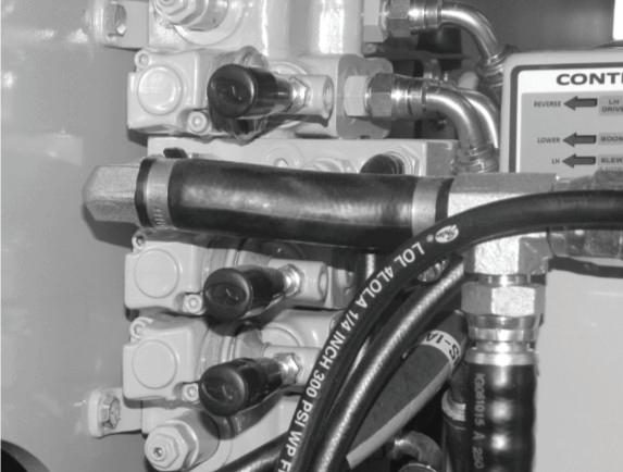
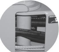
o Ground Station Emergency Controls
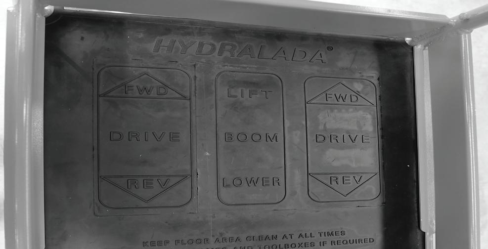
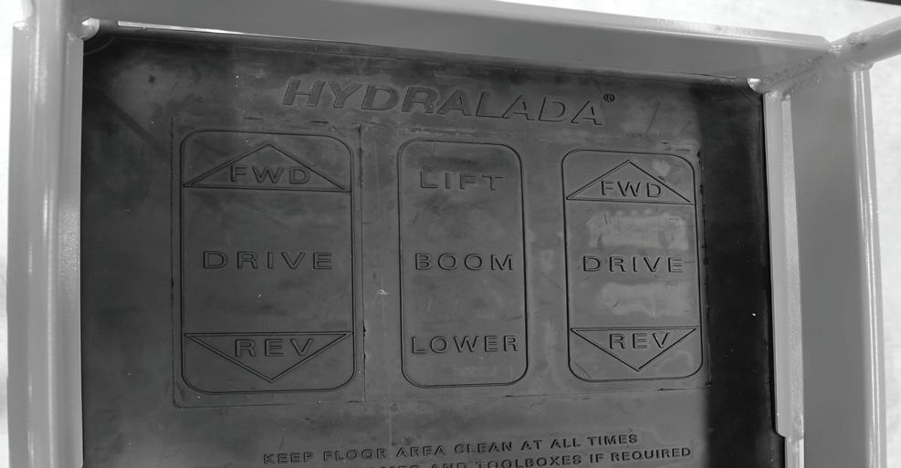
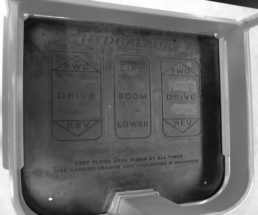
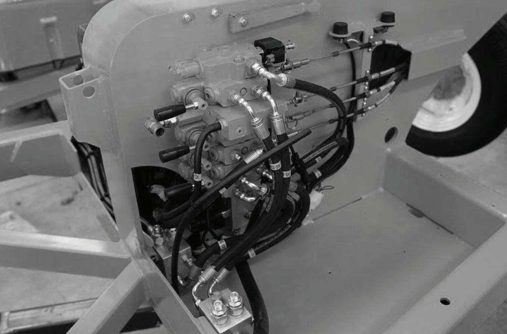
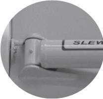
Hydraulic Movement Controls
A manual control lever is mounted to the front of each control section. The decal on the front of the Hydraulic reservoir sets out the function of each lever.
MANUAL MOVEMENT CONTROLS
OPERATING MACHINE MOVEMENTS
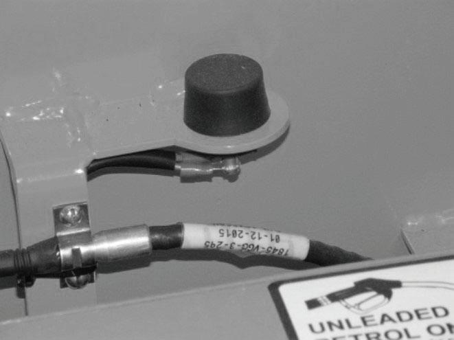
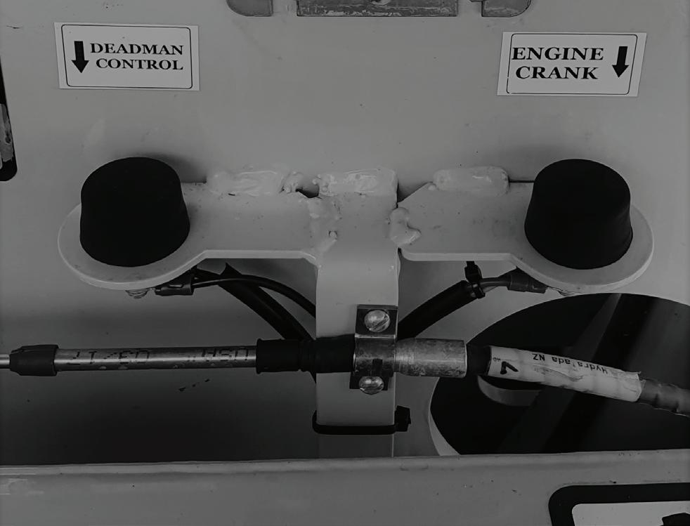
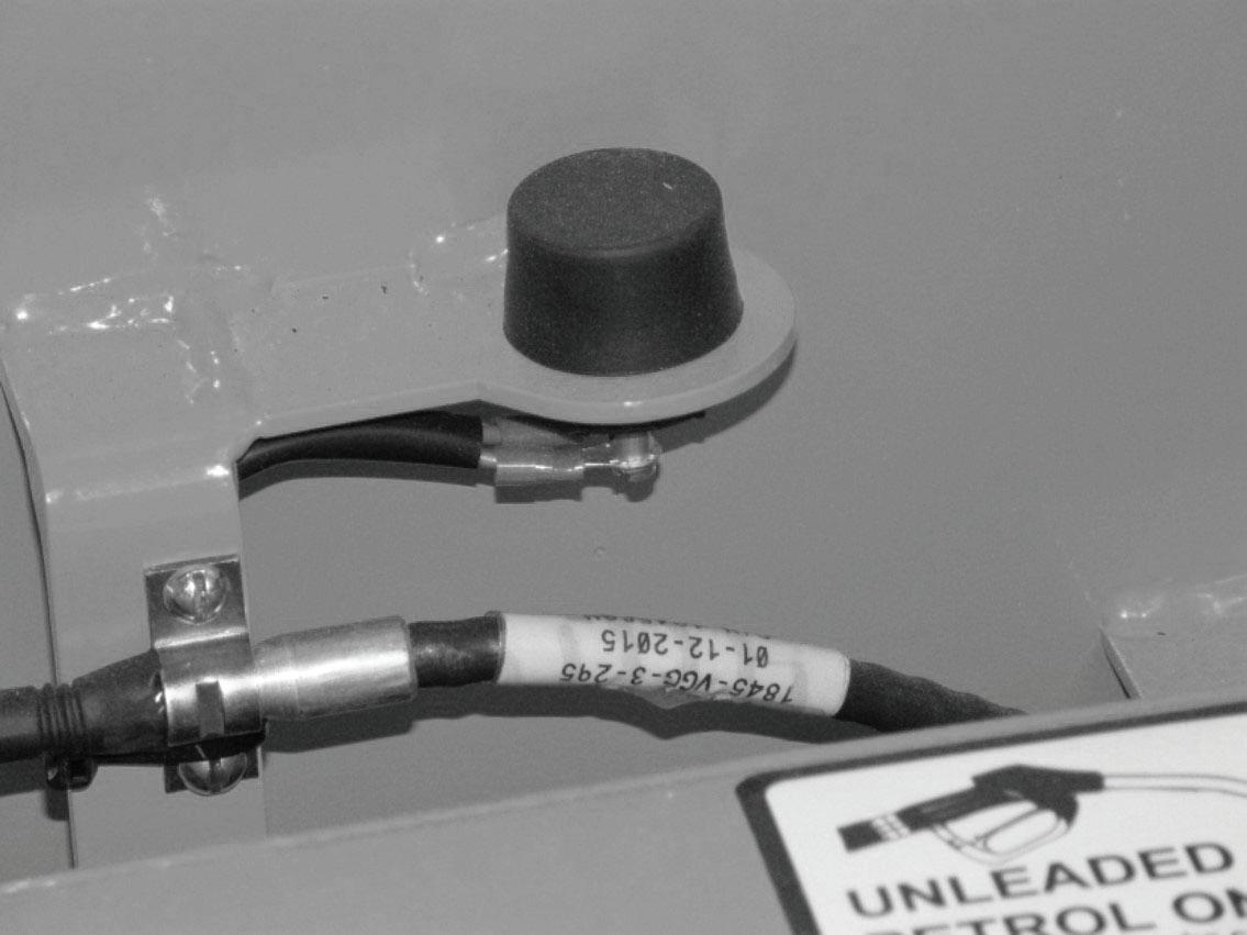
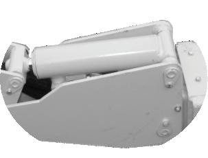
o Emergency Engine Crank
If the engine will not run for any reason, the machine can still be moved by operating the respective Hydraulic Movement Control while simultaneously cranking the engine using this push button. This button is positioned by the hydraulic control valve under the left hand bonnet.
EMERGENCY ENGINE CRANK BUTTON
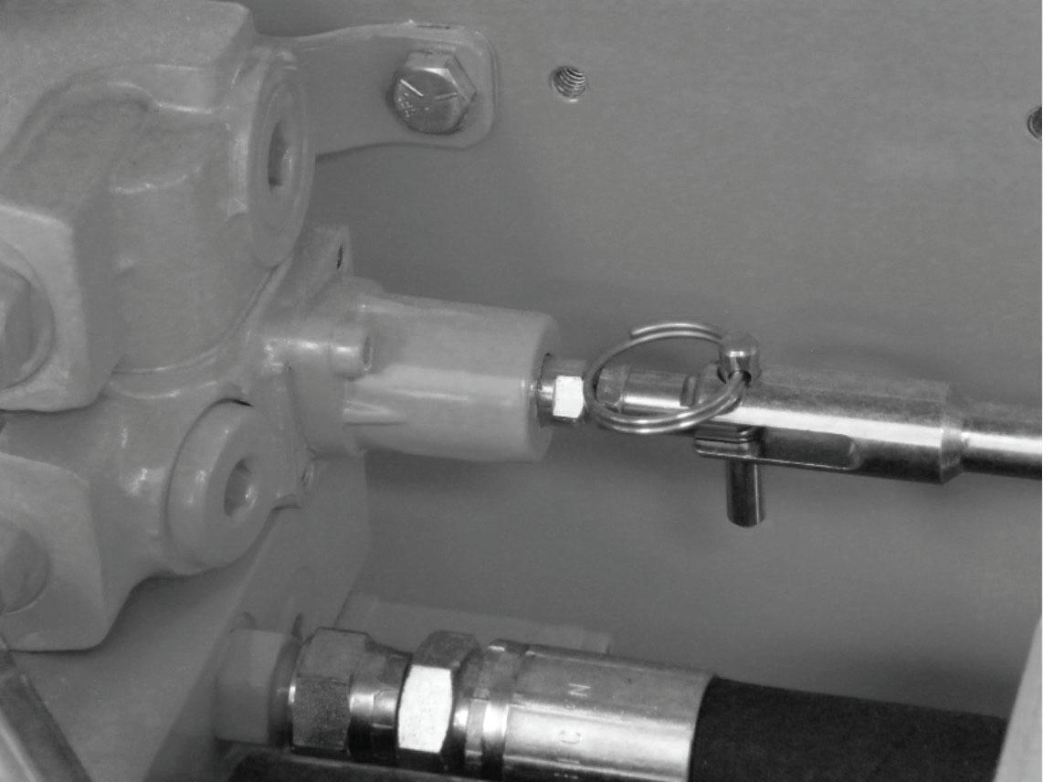
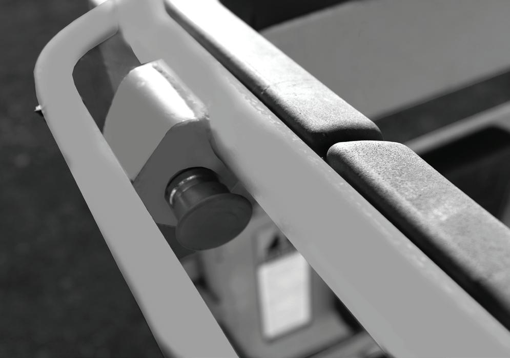
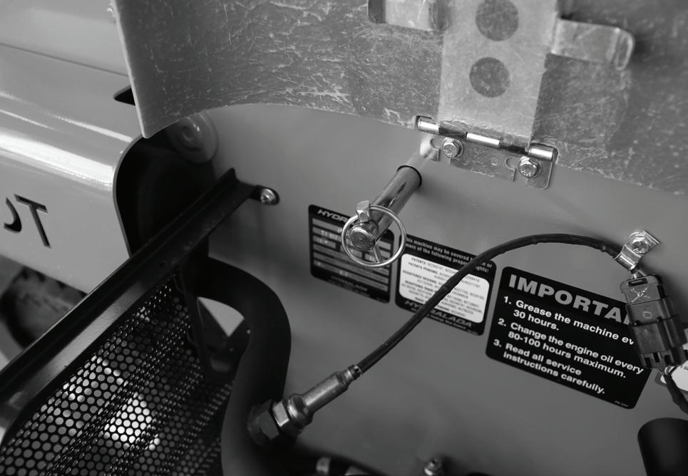
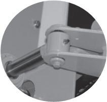
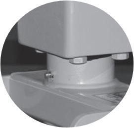
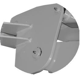
o Quick Release Pins
The clevis pins which connect the control cables to the valve spool can be removed to enable persons at the ground station to manipulate the movements using the manual control levers. This action is only necessary if something is jamming the platform controls or is required to isolate the platform controls to ensure safe retrieval.
REMOVING THE QUICK RELEASE CLEVIS PIN
3. Safety Devices
o Ground Station Function Enable Control
The Function Enable Control is fitted to Hydralada Industrial Model Elevating Work Platforms and must be activated for the Ground Station Emergency Controls to be operational.
GROUND STATION FUNCTION ENABLE CONTROL
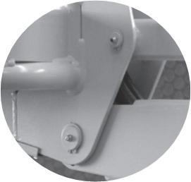
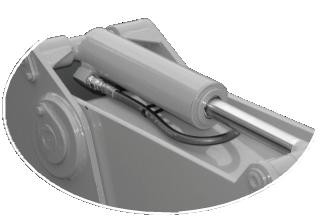
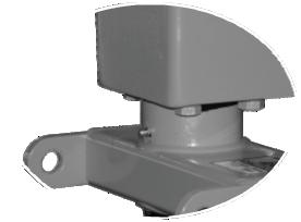
o Platform Locking System
A flow control cartridge and locking Solenoid is built into the base of the Work Platform Hydraulic lifting cylinder. This controls the flow of oil from the lift cylinder, limiting the maximum speed the Platform can be lowered. In the unlikely event of a hydraulic hose failure, this control system will prevent the Platform from lowering uncontrollably.
o Emergency Platform Lowering
A lift control lever is provided under the right hand bonnet to enable persons on the ground to lower the Platform in the event of an Emergency.
o Horn
A button on the Rear of the Work Platform sounds the horn which can be used to attract attention in an Emergency.
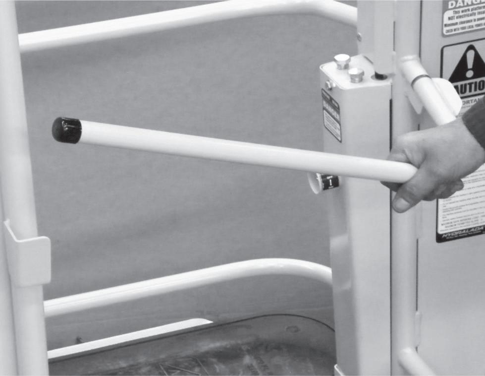
o Switched Mid-rail
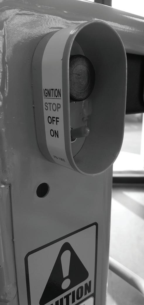
An opening mid-rail is provided to allow convenient access of the Operator into the Platform. As soon as this mid-rail is opened, the engine is shut down, and the starter motor deactivated. If the engine shuts down as a result of the mid-rail being raised, the ignition switch must be activated to the OFF position before leaving the EWP. This is intended to avoid the possibility of any inadvertent operation of any controls in the Work Platform.
SWITCHED MID-RAIL
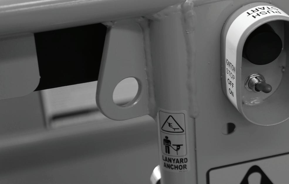
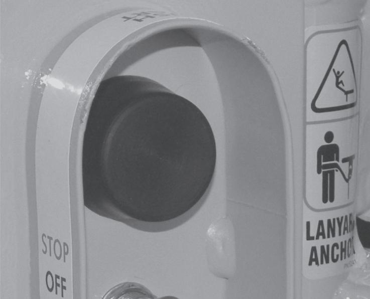
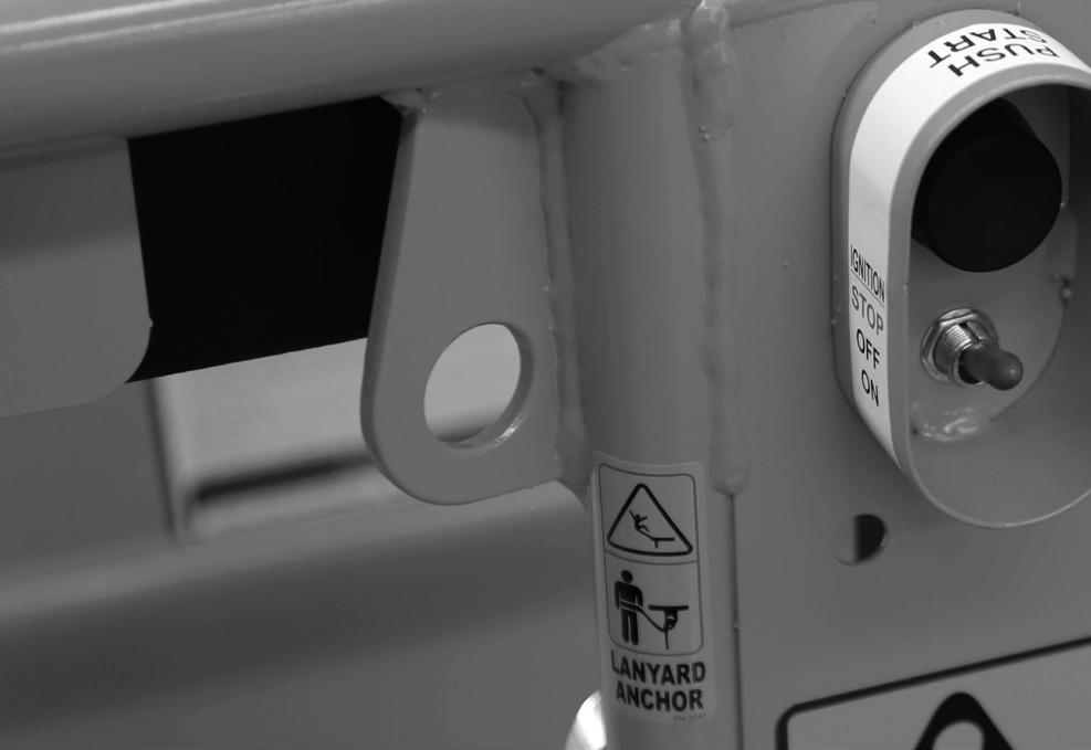
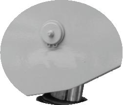
o Lanyard Anchor Point
A Certified Anchor Point is provided on the Work Platform of every Hydralada EWP. This point is intended for the operator to connect a safety harness to the EWP at all times when the machine is being operated. This anchor point should not be used for any other purpose. Hydralada Company recommend that operators use an ‘Approved Safety Harness’ which is available from the Hydralada Spare Parts Department. CERTIFIED ANCHOR POINT
3. Safety Devices
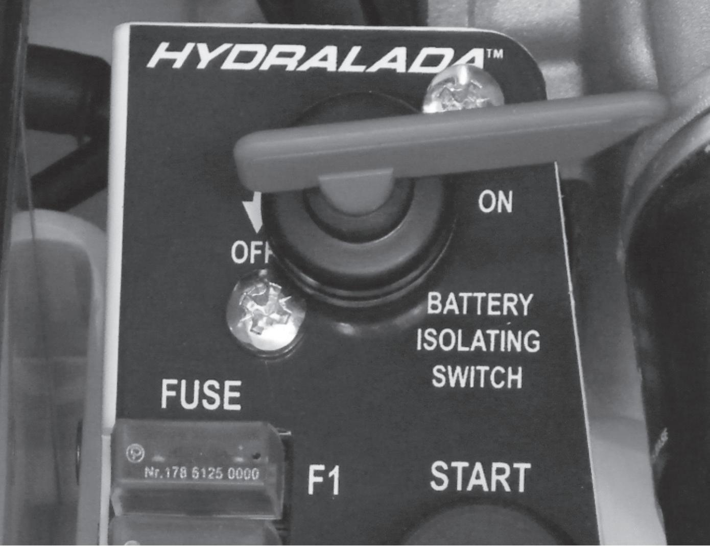
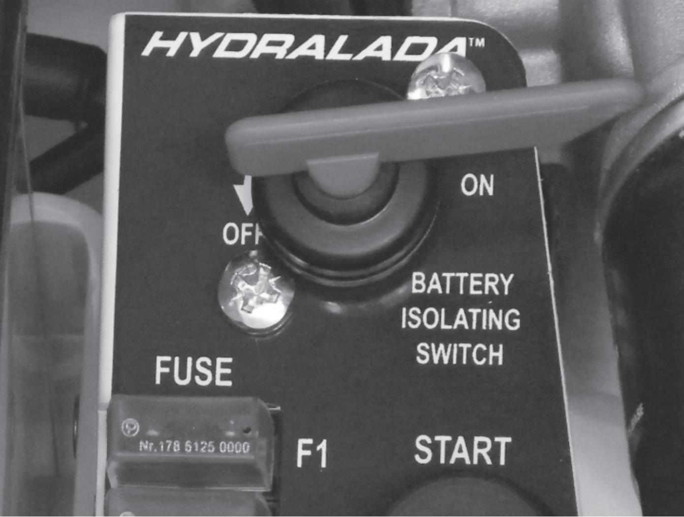
o Battery Isolating Switch
A red key switch is located on the control panel in the right hand engine bay. On Elevating Work Platforms fitted with Diesel engines these are located under the left hand bonnet. Turning this fully in the anti clockwise direction isolates the battery and deactivates the elevating work platform’s electrical circuits.
By turning this key anti-clockwise past the off position, the key can be removed to immobilise the EWP.
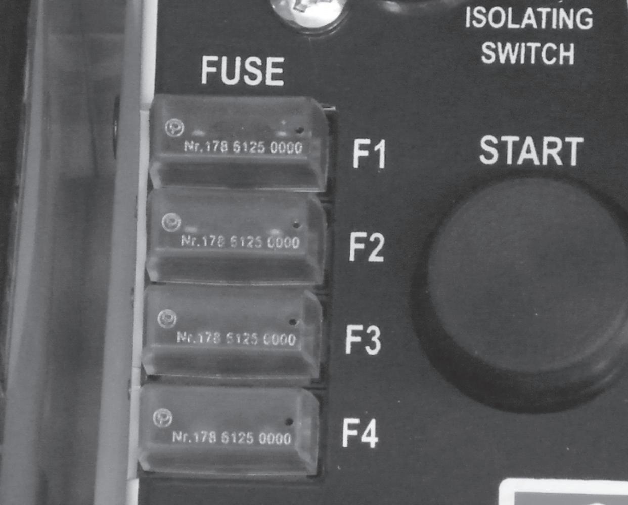
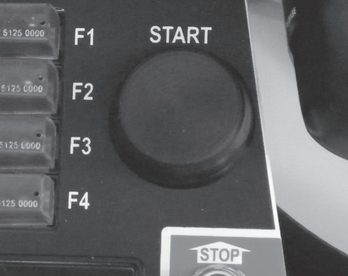
IMPORTANT
Fuses should only be fitted in stations F3 and F4 when this equipment is installed on the EWP. On standard Elevating Work Platforms these stations should be left empty.
SYSTEM FUSES
BATTERY ISOLATING SWITCH UNDER THE RIGHT HAND BONNET
CAUTION
Do not use a higher rated fuse or in any way attempt to modify the fuse connection. If replacement fuses fail refer the problem to a qualified service technician.
o Electrical Fuses
These are mounted behind the engine under the right hand side bonnet. On Elevating Work Platforms fitted with Diesel engines these are located under the left hand bonnet. These fuses protect all the electrical circuits in the event of an electrical overload or short circuit.
It is important that only the correct fuses as shown on the chart are used in the respective positions
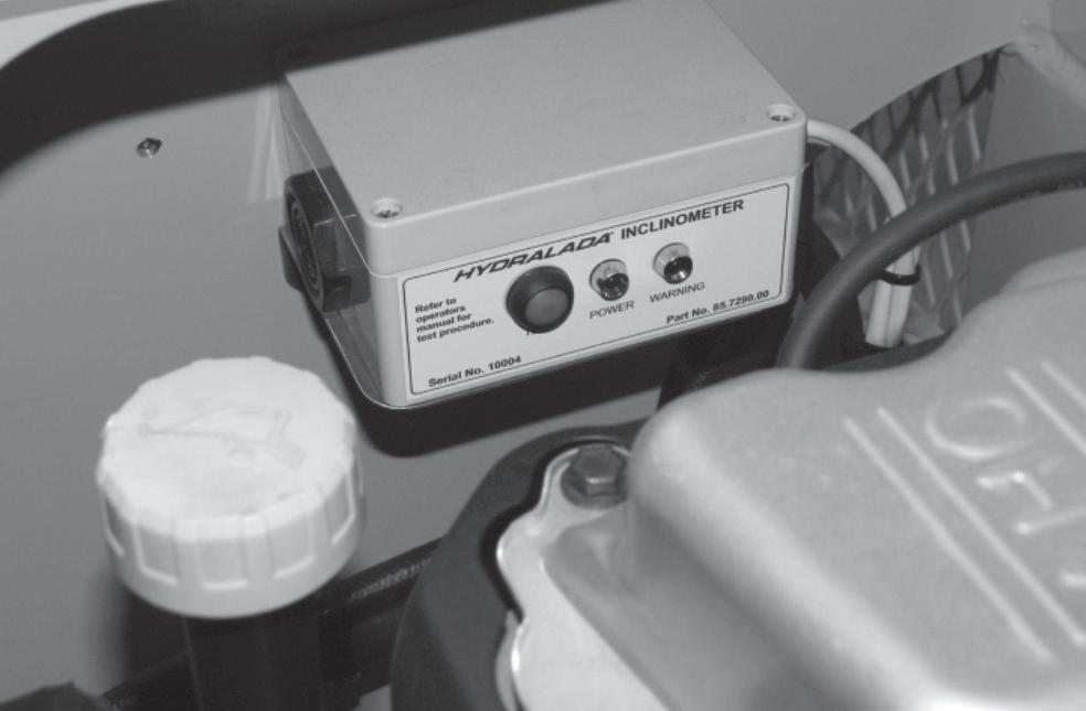
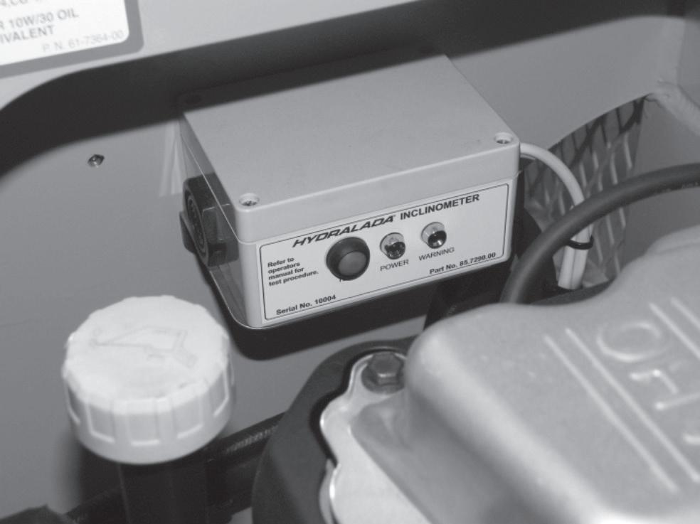
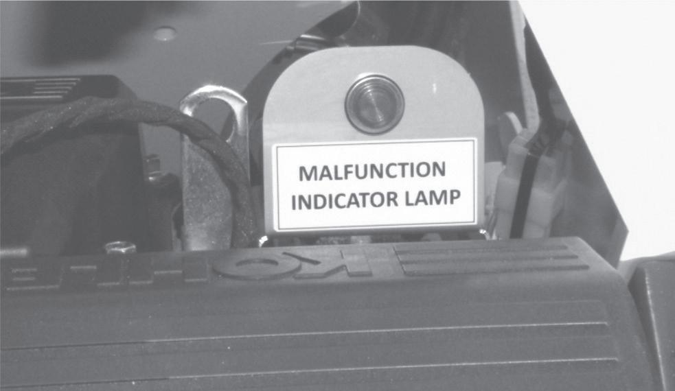
o Inclinometer
The Inclinometer is mounted in the centre of the EWP inboard of the engine. This device monitors the inclination of the EWP whenever the boom is elevated above the travel position, and sounds an audible alarm when the inclinationof the EWP approaches the maximum allowable limit. The audible alarm will emit an intermittent beep as the EWP nears the inclination limit and a continous beep when the EWP reaches the inclination limit. The Power LED is lit whenever the boom is elevated above the transport position, confirming the device is active.
F4
F4 Special equipment
HYDRALADA
3. Safety Devices
WARNING
Inclinometers are factory calibrated for each individual EWP. NEVER tamper with or move inclinometers from off the EWP or between Elevating Work Platforms.
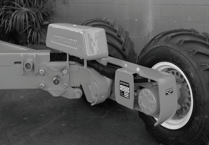
o Drive Wheel Brakes
Elevating Work Platforms with mechanical brakes have them mounted in the drive wheels of at least one drive axis.
These provide a failsafe brake whenever the machine is stationary. The brake systems which are fitted to the Hydralada EWP are completely automatic in their operation meaning they require no special operating procedures.
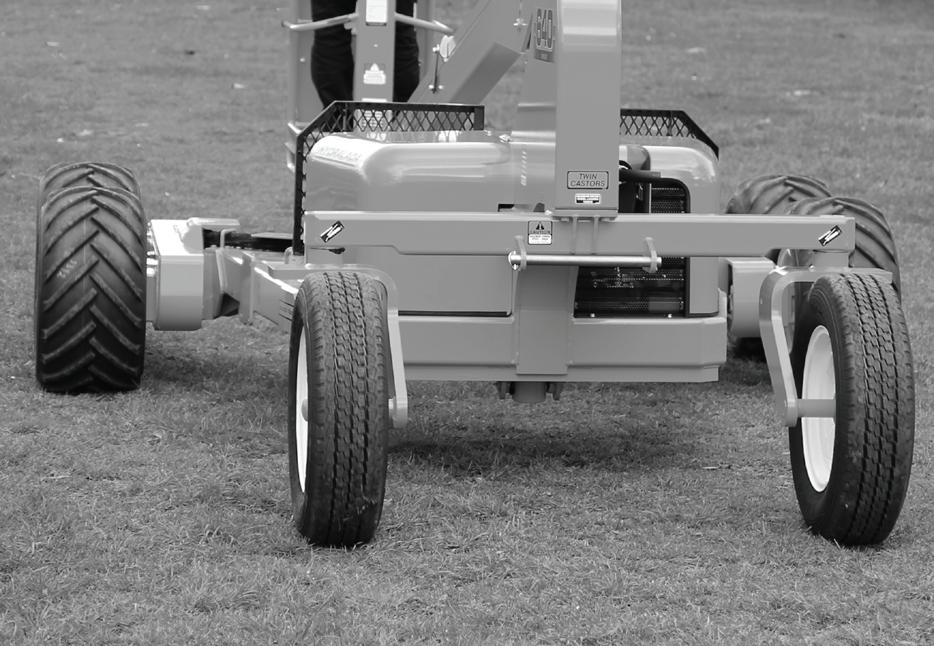
o Water-filled Tyres
The tyres on the Hydralada EWP are water filled to provide stability for the machine.
It is important that the weights of the wheel assemblies are maintained to the values listed in the Specifications charts on Page 1-1 of this Manual.
DAN G E R
Never operate the EWP fitted with non standard wheel assemblies, or with wheel assemblies which weigh less than the specified weight (refer to Stability Certificate in Delivery Manual or decals on EWP).
n Optional Safety Devices
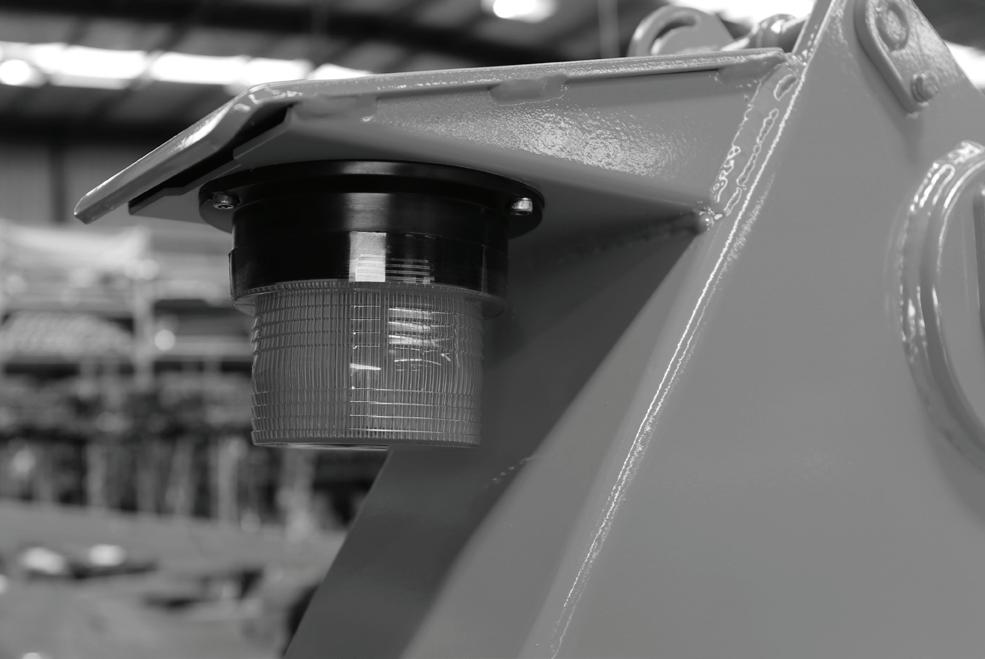
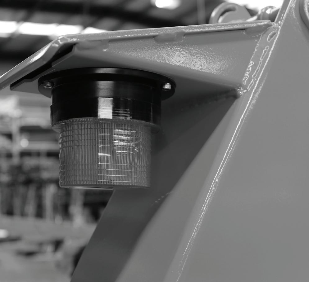
o Rotating Beacon
Rotating beacon options are fitted where an EWP will be used near vehicular traffic. This is an orange beacon mounted on the tail of the machine.
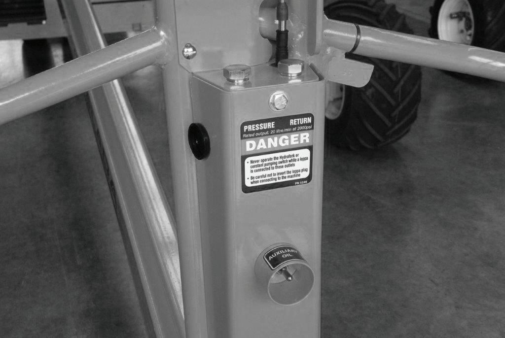
o Auxiliary Hydraulic Oil Outlet
A control module operating the auxiliary hydraulic oil outlet shuts down the oil supply automatically whenever the engine of the EWP is shut down.
This means, to restart the flow of oil, the switch must be activated again once the engine is running.
3. Safety Devices
o Safety Decals and Placards for Compact 300/360GII
Look to see that all placards and decals are in place and legible. Replace any missing or illegible placards or decals before placing the Hydralada EWP into service for the daily work shift.
Decal and placard kits for the Hydralada EWP are available from Hydralada dealers.
3. Safety Devices
3. Safety Devices
o Safety Decals and Placards for Maxi 440/540/640/750/802
Look to see that all placards and decals are in place and legible. Replace any missing or illegible placards or decals before placing the Hydralada EWP into service for the daily work shift.
Decal and placard kits for the Hydralada EWP are available from Hydralada dealers.
3. Safety Devices
3. Safety Devices
N O G O Z O N E
4. Controls
n Description of the Controls
This Chapter locates and explains what each control does, but DOES NOT explain how to use the controls to produce useful work. For that information, refer to the ‘Operation’ section after you have read this section. If you have optional equipment installed on your Hydralada EWP, that is not explained here, then refer to the ‘Options’ section.
Hydralada Company offer a wide range of options for the Hydralada EWP. This section covers all the available control options, but you will need to refer to the sections that specifically apply to your EWP and its configuration.
—IMPORTANT—
It is important not to operate the starter unless the engine is completely stopped.
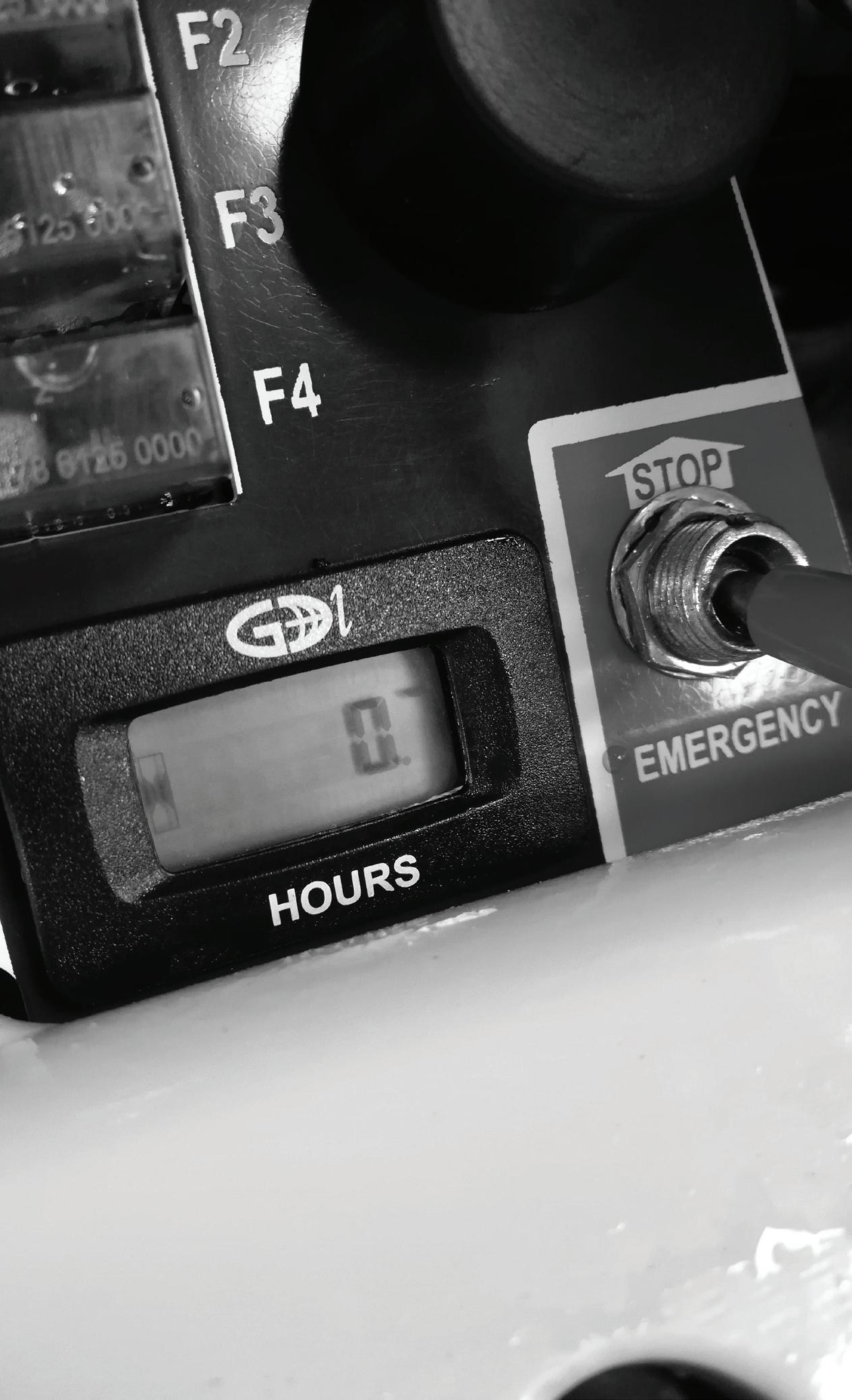
n Engine Bay Controls
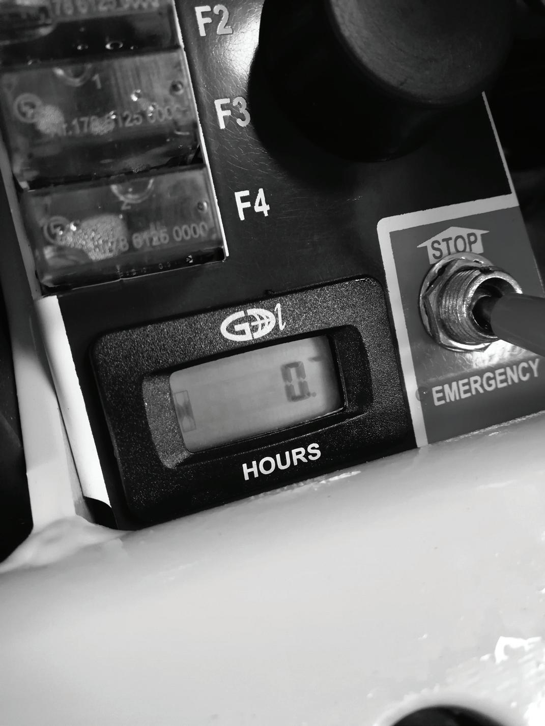
o Hour Meter
o Battery Isolating Switch
A red plastic key battery isolating switch is mounted at the left hand end of the small control panel. It is under the left hand bonnet of Diesel powered Elevating Work Platforms, or under the right hand bonnet for all other models. Releasing this plastic key in an anticlockwise direction isolates the battery from the entire electrical system.
• In an Emergency situation, turning this switch off will isolate the battery.
• This means that this switch must be in the ‘On’ position before the EWP can be started.
• This switch can be used as a security device to immobilse the EWP by turning it past the ‘Off’ position and removing the plastic key.
Technicians can use this switch to isolate the battery from the electrical system when they are carrying out maintenance.
This chapter does not provide information on the location or operation of the ‘Emergency stop’ and ‘Emergency lowering’ controls. For information on those controls and their operation refer to ‘Safety Devices’ Chapter 3, or ‘Emergency Operation’ Chapter 7.
BATTERY ISOLATING SWITCH
ENGINE HOUR METER
4. Controls
o Engine Choke Control
The Choke control is mounted on the front of the Kohler Command CH23S twin cylinder engine. It may be necessary to use this when the engine is being started from cold.
There is no Choke on the Fuel Injected engines.
MOVING THE CHOKE CONTROL TO THE START POSITION ON THE CH23S ENGINE
n Paired Controls
These are controls which perform the same function at both the Engine Bay and Platform control stations.
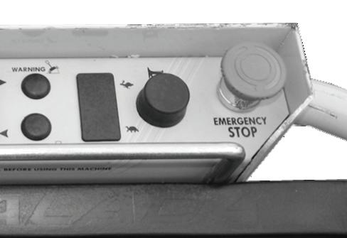
o Engine Emergency Stop Switch
A red switch is located on the control panel in the right hand engine bay of gasoline engines, or under the left hand bonnet of Diesel engined Elevating Work Platforms, and a similar Red switch on the rear of the Work Platform are connected in parallel.
To start the engine and operate the EWP, both of these switches must be in the down ‘On’ position.
EMERGENCY STOP SWITCH UNDER THE RIGHT HAND BONNET IN THE RUN POSITION
ON/OFF SWITCH ON THE REAR OF THE WORK PLATFORM IN THE RUN POSITION
In an Emergency situation, turning either of these switches off will immediately shut down the engine, and therefore all machine functions.
Note: The Emergency Stop Switch on the rear of the Work Platform has an extra centre position which shuts down the EWP in the same way by closing the fuel supply to the CH23 engine. However, there is a small delay as the engine burns any fuel already present in the induction system before the shutdown is completed. This position is intended to be used as the regular shutdown procedure to eliminate any risk of backfiring on these engines.
4. Controls
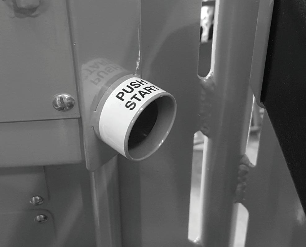
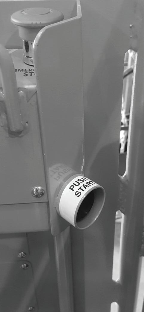
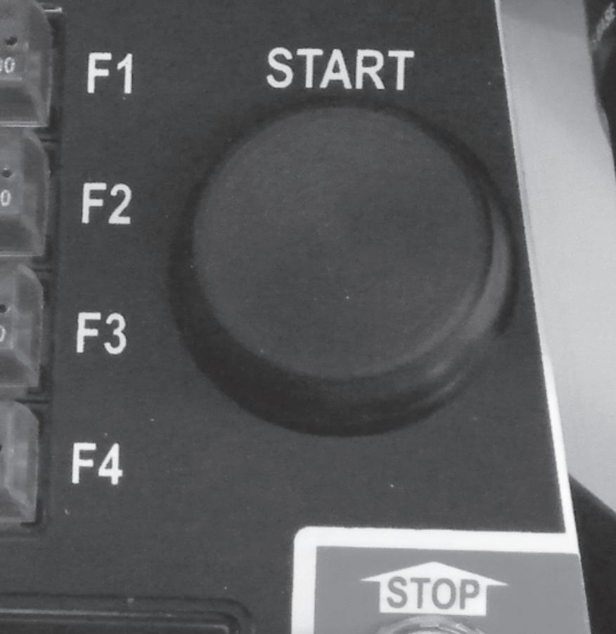
o Engine Starter Button
A Push Button on the control panel in the right hand engine bay of gasoline powered Elevating Work Platforms or under the left hand bonnet of Diesel powered models, and a similar Push Button on the rear of the Work Platform are connected in parallel.
Pressing either of these two buttons, with both Emergency Stop Switches in the ‘On‘ position, will operate the Engine Starter.
n Work Platform Controls
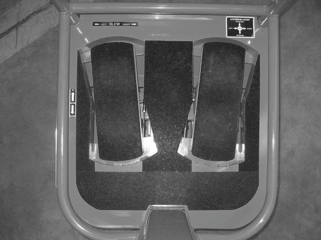
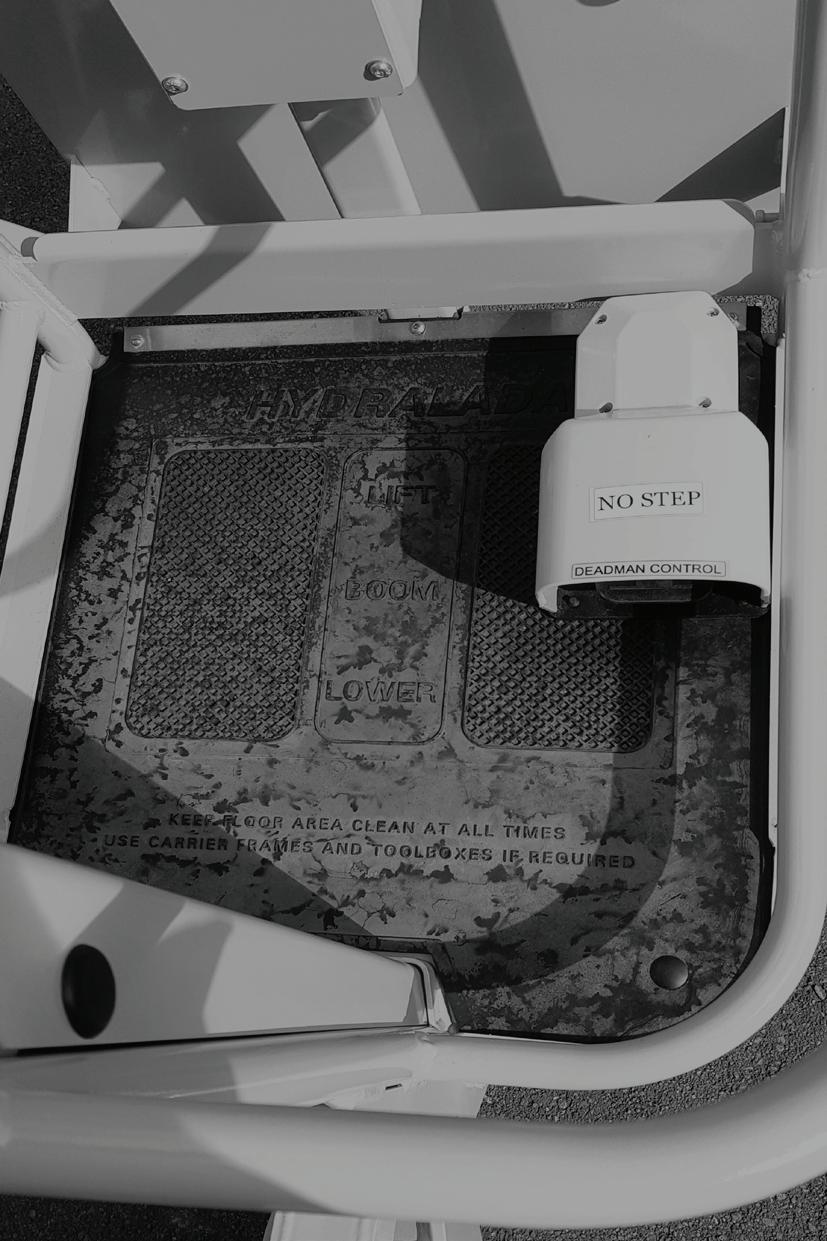
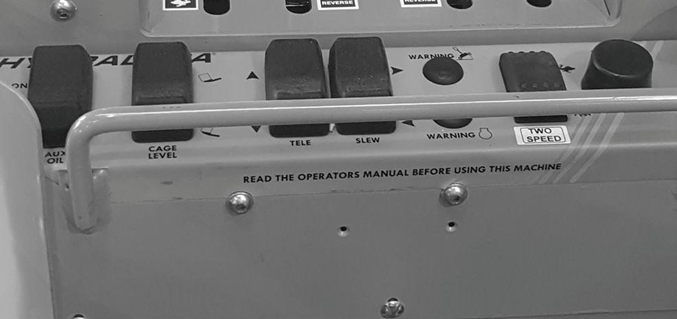
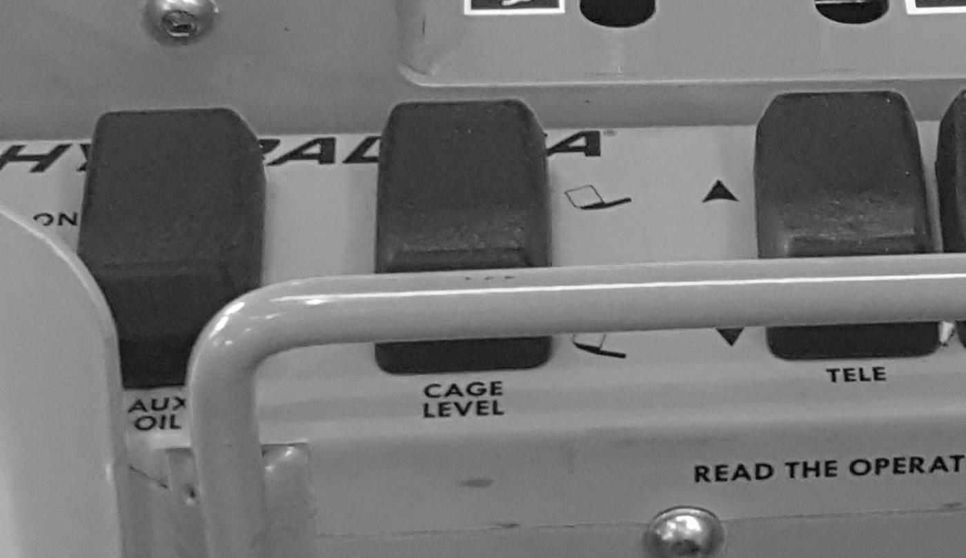
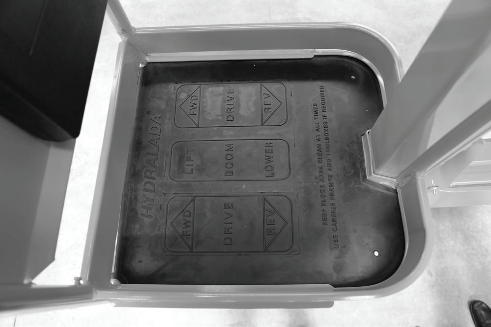
The standard Hydralada configuration for the control of the machines movements is by foot operated pedals as shown in the illustrations on the following page.
The operation of these controls is as follows:
o Drive Pedal Controls
The Drive motors are controlled by the two outer pedals. Each pedal controls the drive wheel on the respective side of the EWP as shown below. The operation these pedals are shown on the floor mat of the EWP.
4. Controls
It is quite acceptable (and part of normal operation) to operate any or all of the pedal controls simultaneously to drive and lift/lower at the same time if desired.
o Platform Lift Pedal Control
Pressing the centre pedal forward lifts the Work Platform. Pressing the centre pedal back lowers the Work Platform.
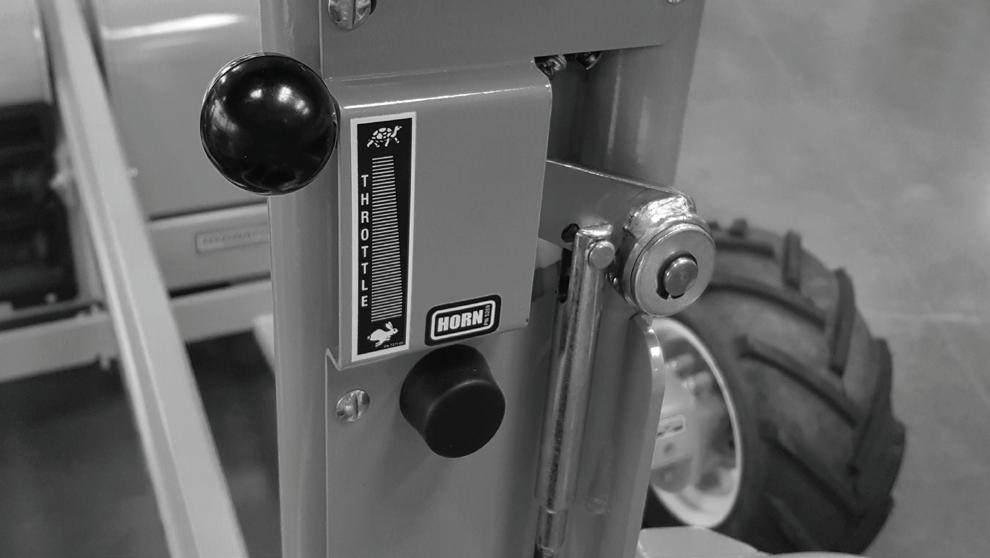
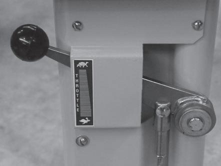
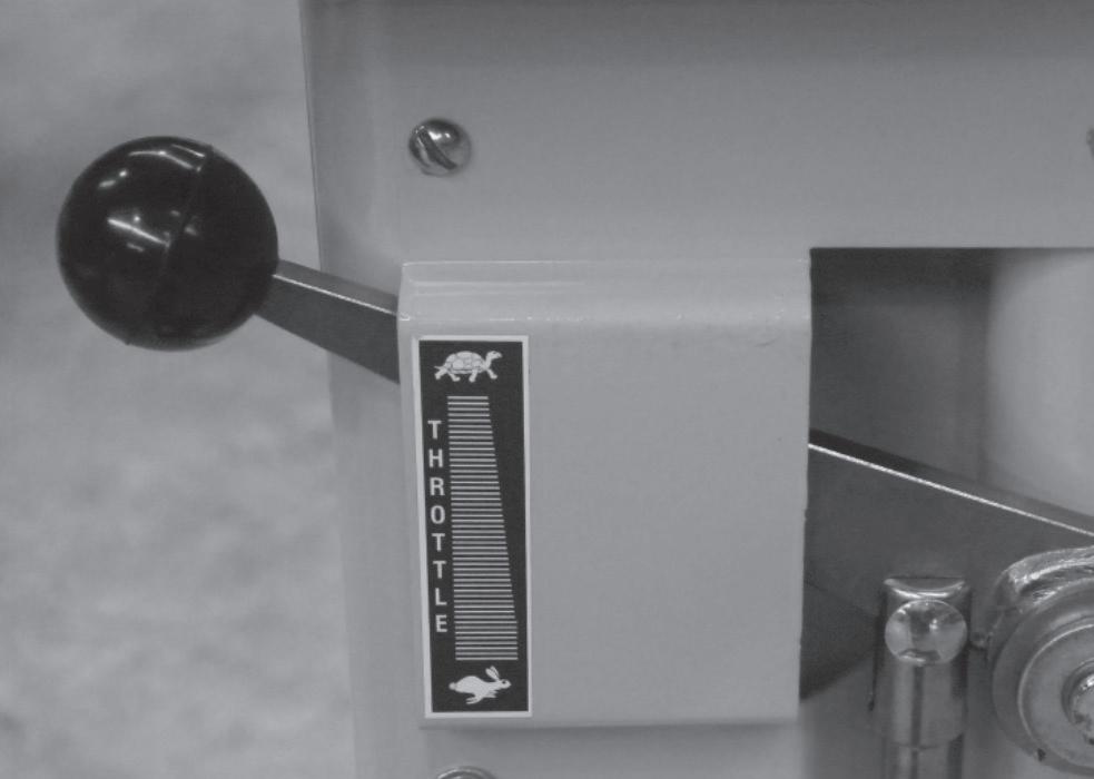
o Engine Throttle Control
This control controls the Governor setting and engine speed.
See Chapter 6-4 for detailed instructions for the correct operation of this control.
n Controls For Optional Equipment
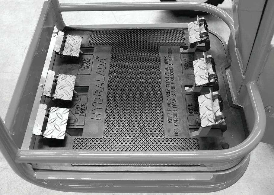
o Six Pedal Platform Controls
The controls in this Work Platform are similar to the standard Work Platform pedals, excepting for the
layout.
The operation of these pedals are shown on the floor mat of the EWP.
This control system has a locking device on the pedal that needs to be activated before the control can be depressed for operation.
o Two Pedal Control
This system uses a single pedal to control the drive. Pressing either the toe or heel determines the direction of the EWP, while rotating the pedal determines the direction of travel.
SIX PEDAL PLATFORM WHEEL DRIVE CONTROL
SIX PEDAL PLATFORM BOOM LIFT CONTROL
TWO PEDAL CONTROL
4. Controls
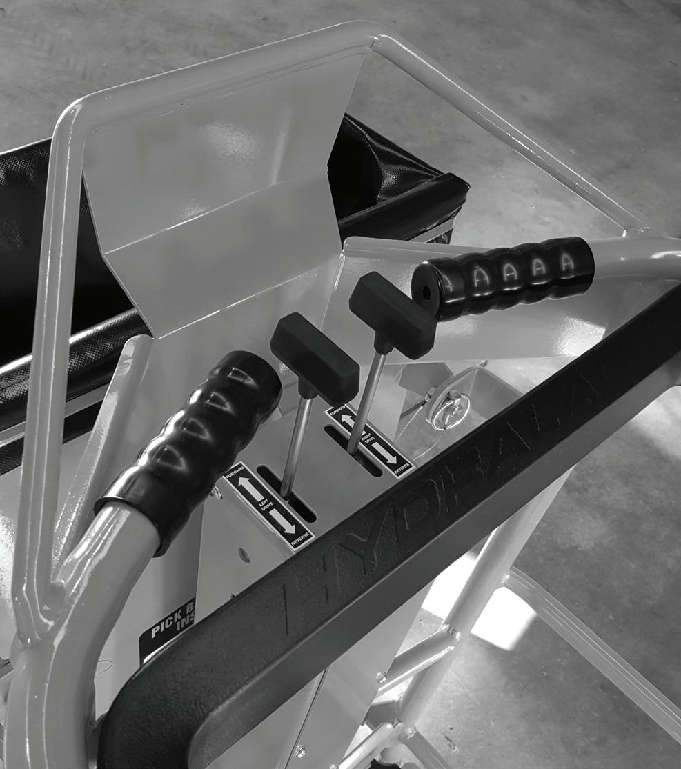
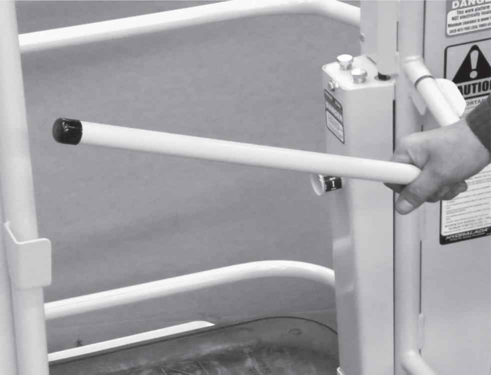
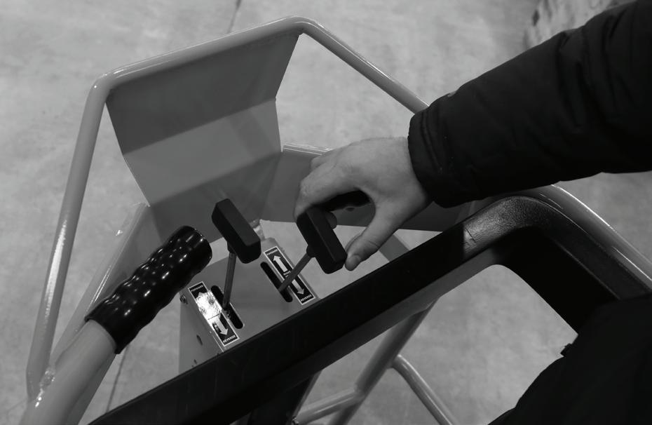
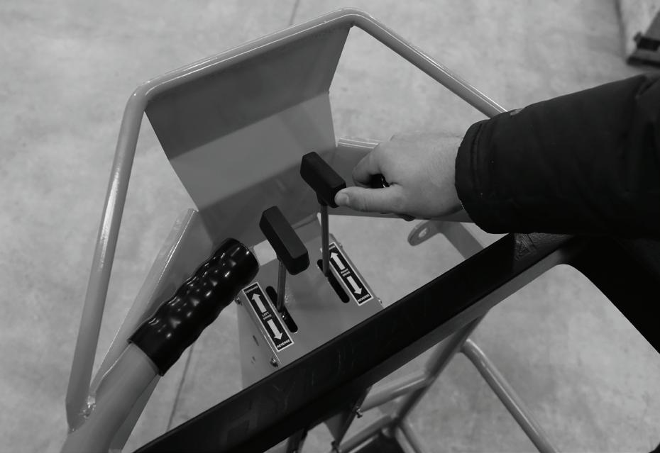
o Tiller Lever Hand Operated Controls
This system is mounted at the front of the Work Platform and provides hand support grips for the operator. This allows the operator to grip the supports whilst utilising the thumb and fingers to activate the controls.
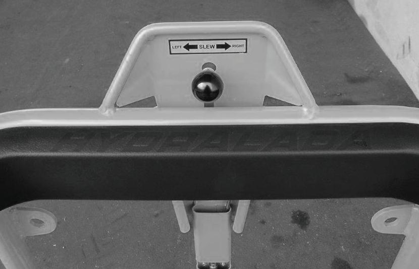
o Work Platform Slew Control
This controls the slewing of the Work Platform through a total arc of 90 degrees. The control lever is mounted in the front of the operators Work Platform. Moving this control lever to the left or right results in the respective movement of the Work Platform.
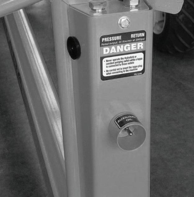
o Auxiliary Hydraulic Oil Outlet
The on/off control switch is mounted behind the operator inside the Work Platform.
The operation of the control switch is shown on the decal. Operating the ‘self centring’ switch downwards when the engine is running begins the flow of hydraulic oil from the outlet port in the Work Platform, while the flow is discontinued by moving the switch upwards.
Once the EWP is restarted its electrical system will automatically discontinue the supply. To restart the flow of oil, the switch must be operated again once the engine is running.
The pressure from the auxiliary oil port is limited to 2000psi with the standard hydraulic tool flow being delivered around 2000 engine rpm. For further details contact Hydralada technical division.
o Two Speed Control
This system is controlled by a switch mounted on the rear of the Work Platform. Moving this switch to the ‘Low’ position halves the speed of all hydraulic functions.
Moving the switch to the ‘High’ position brings the speed to the same as a standard machine. The system is useful for applications where the EWP is to be operated at slow ground speeds.
o Rotating Beacon Switch
When this option is fitted, a switch is mounted under the right hand bonnet beside the hour meter to deactivate the beacon.
Auxilary Oil Supply On/Off Swtich
CENTRE MOUNTED PLATFORM SLEW CONTROL
AUXILARY OIL SUPPLY OFF/ON SWITCH
TILLER LEVER HAND OPERATED CONTROLS
4. Controls
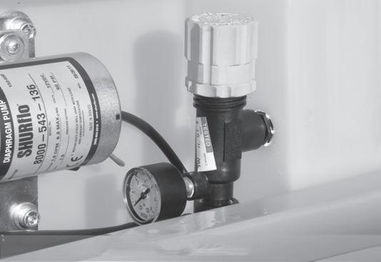
o Irrigated Picking Bag – Mangoes Product Pump
This is turned off / on with the switch mounted on the rear of the Work Platform. Pressure Regulator
The pressure to the picking bag is controlled by the pressure regulator which is mounted beside the Product Pump.
o Platform Function Enable Control
The Function Enable Control is fitted to Industrial Model Elevating Work Platforms and must be activated for the platform controls to be operational.
o Hydrafork Control
4. Controls
o Two Man Platform Controls
This Two Man Platform is fitted with Tiller Lever Hand Controls and a foot activated Function Enable Control for Industrial Applications. The Foot Function Enable Control must be activated for the platform controls to be operational.
n Controls for Maxi 750 Models Only
o Boom Telescoping Controls
Operating the boom tele switch moves the inner section of the boom in or out as directed by the arrows.
o Work Platform Slew Switch
Operating the platform slew switch moves the work platform to the left or right as directed by the arrows.
o Work Platform Level Switch
Operating the platform level switch changes the level of the work platform. It may be necessary to adjust this from time to time. This should only be operated when the boom is in the fully lowered position.
o Auxiliary Oil Switch
The operation of the control switch is shown on the decal. Operating the ‘self centering’ switch ON when the engine is running begins the flow of hydraulic oil from the outlet port in the work platform. The flow is discontinued by moving the switch to the OFF position.
Once the EWP is restarted the machines electrical system will automatically discontinue the supply. To restart the flow of oil the switch must be operated again once the engine is running. The pressure from the auxiliary oil port is limited to 2000psi with the standard hydraulic tool flow being delivered at approx. 2000 engine rpm.
For further details contact Hydralada Company Technical Department.
AUX OIL / PLATFORM LEVEL SWITCHES
TWO MAN PLATFORM CONTROLS
Tiller Lever Hand Controls
5. Daily Inspection and Maintenance
n Daily Inspection
At the start of each work day (or 8 hour shift), a qualified Hydralada EWP operator must perform the Daily Inspection and Maintenance as listed in the table below.
NOTE
Further information on items such as engine oil, hydraulic oil, oil filters, air cleaner elements, engine adjustments etc. can be found in “Servicing” chapter 11.
The purpose of this procedure is to keep the Hydralada EWP in proper working condition and to detect any signs of malfunction at the earliest possible time. Defective parts and/or equipment malfunctions jeopardise the safety of the operator
Item
Emergency lower - ground
Engine fuel level
Fuel tank cap
Fuel leaks
Engine oil level
Engine cooling
Wiring
Battery terminals
Battery fluid level
Hydraulic oil level
Hydraulic oil leaks
Bolts and fasteners
Wheels and tyres
Structural damage and condition
Lanyard anchor point
Lanyards and safety harnesses
Drop down Work Platform midrail
Rotating beacon (option)
Emergency stop switches - ground
Inclinometer
Air filter
Work Platform controls
Hour meter
Placards and decals
Wheel nuts
Hub nuts
Pin Brake disc wear
and other personnel, and can cause damage to the EWP. Do not attempt to make repairs unless you are authorised to do so.
The rest of this chapter shows how to perform the Inspection and Maintenance required for each item in the Daily Inspection and Maintenance Table.
DAN G E R
DO NOT operate a Hydralada EWP that is known to be damaged or malfunctioning. Repair all equipment damage or malfunctions before placing the EWP into service.
Once your inspection is completed, fill in the EWP Log Book, taking care to record any matters which may need further attention.
Service Required
Check operation (causes correct motion)
Check the fuel level in the tank is sufficient
Check to see that the cap is tight
Visually inspect (hoses and connections)
Check oil level (between dipstick lines)
Check that grills and intakes are not blocked
Visually inspect (installation, condition)
Visually inspect (no corrosion)
Check fluid level (just covering the separator plates)
Check the operating hours to confirm the current service period. If the EWP has turned into another 100 hour period it must be serviced as shown on the serviceman‘s check sheet.
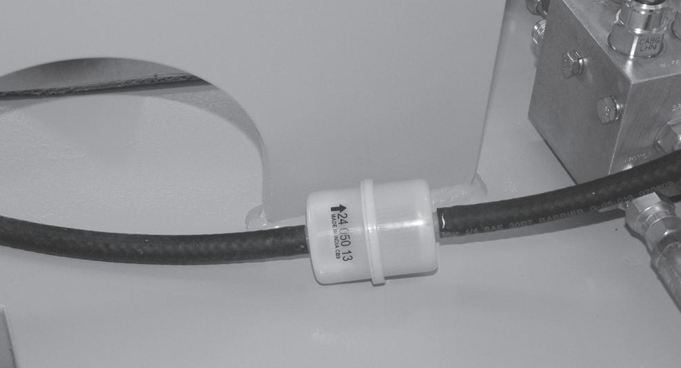
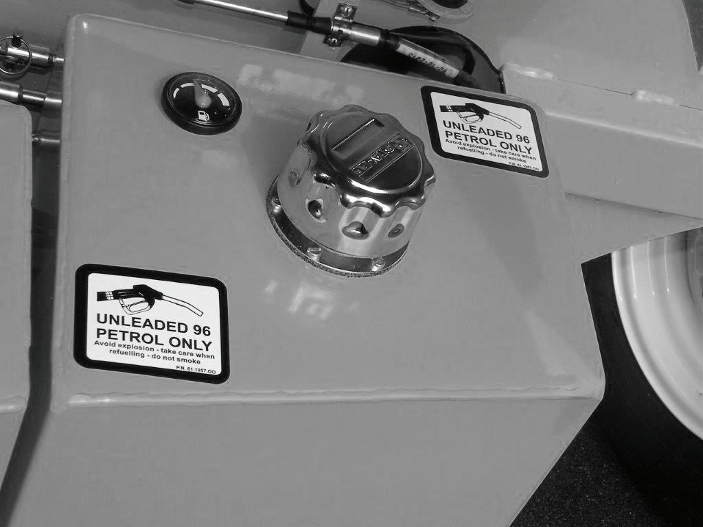
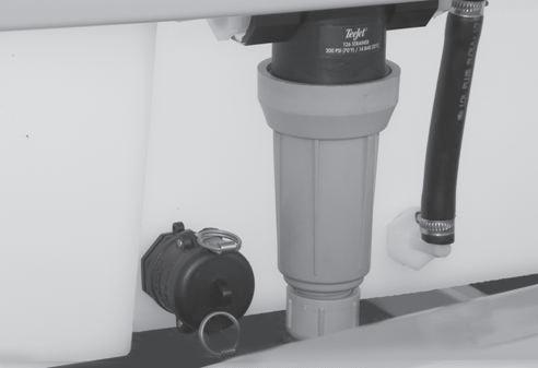
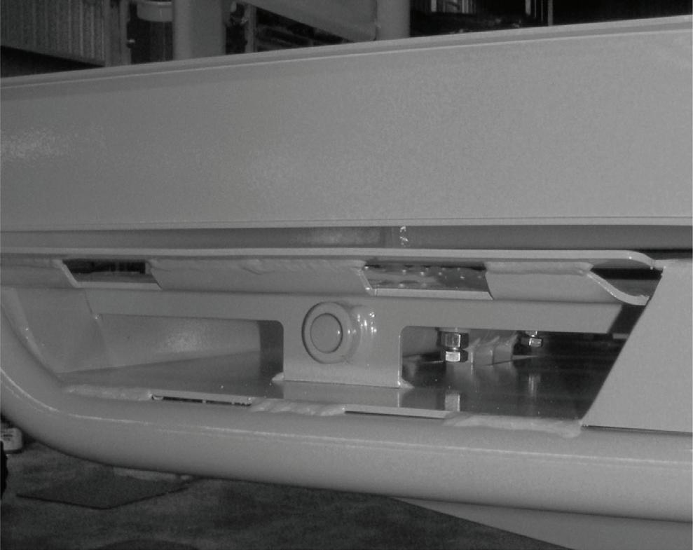
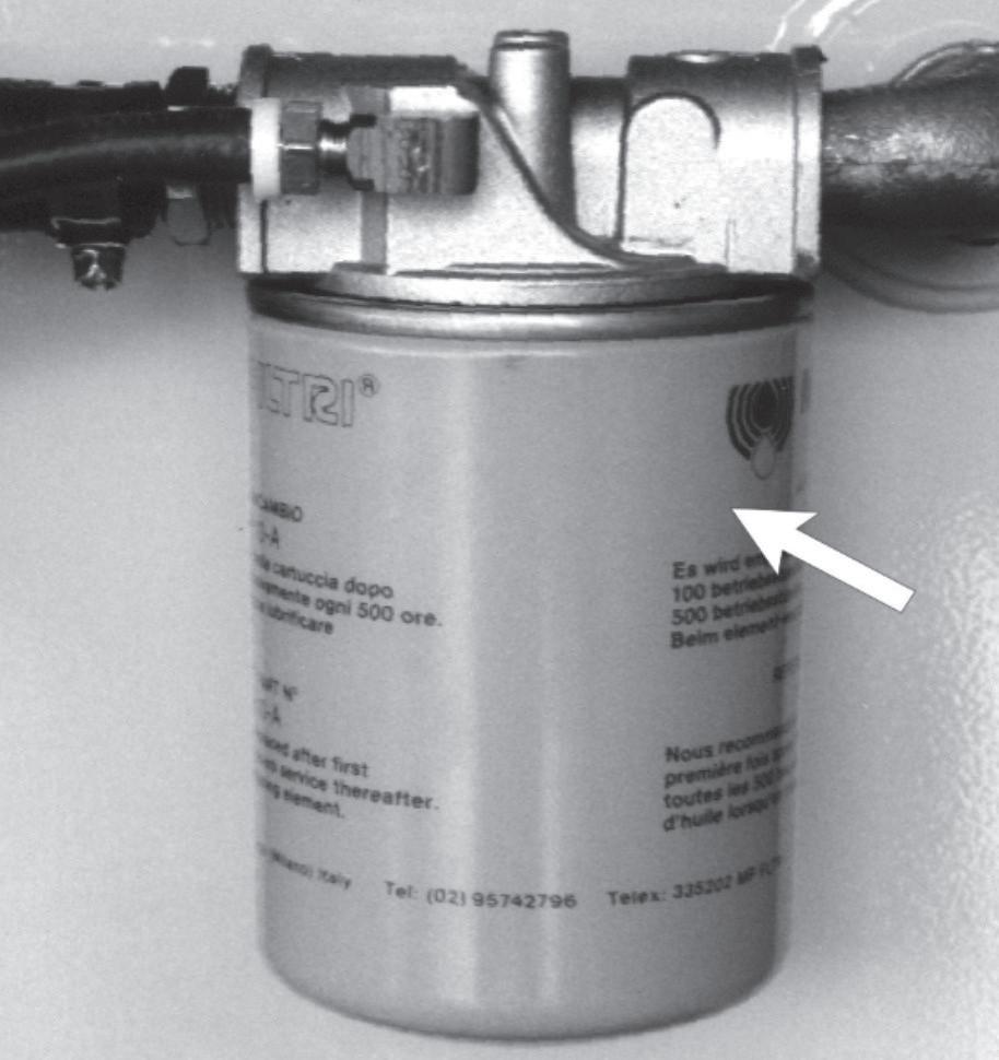
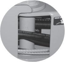
o Fuel Leaks
Visually inspect the fuel tank and any visible fuel line for damage and leaks.
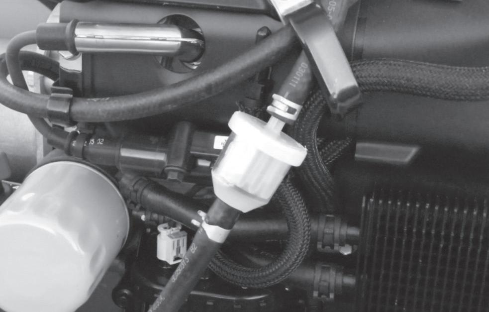
• Inspect the in line filter which lies on the floor of the EWP. If there is any visual indication of contamination the filter assembly should be replaced.
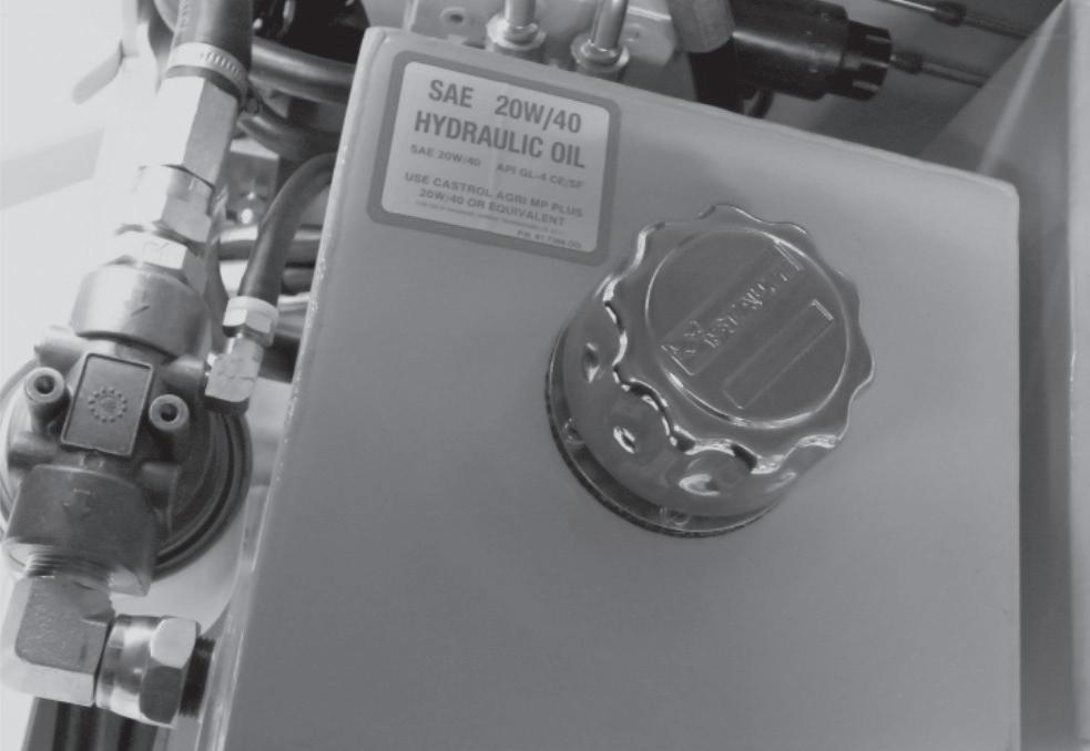
o Hydraulic Oil Level
o Fuel Level
Check the fuel gauge to see that the fuel tank is full. Check to see that the tank cap is in place and is tight. Visually inspect that there are no defects in the sealing surfaces of the Fuel Tank Cap
To check the hydraulic oil level the boom must be completely lowered and the engine turned off. Oil must be added to the system if the level is not clearly visible in the filler neck.
The minimum hydraulic oil level is 70mm from the top of the internal screen and the maximum is 50mm from the top of the internal screen.
If it is necessary to add hydraulic oil, refer to the ‘Specifications’ chapter of this manual for type and grade of hydraulic oil. Remove the quarter turn filler cap, and add oil until the reservoir reaches the correct level.
Always use good quality regular unleaded gasoline. Using fuels containing lead may result in the failure of the spark plug and excessive carbon deposits in the combustion chamber. See ‘Specifications’ chapter 1 for fuel octane and grade.
FUEL TANK
HYDRAULIC RESERVOIR AND FILLER CAP
ENGINE HOUR METER
FUEL FILTER
5. Daily Inspection and Maintenance
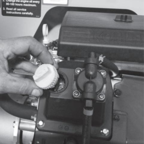
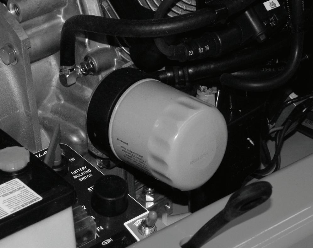
o Checking the Engine Oil Level
With the engine turned off, remove the dipstick located on the top rear of the engine, and wipe the oil off. Re-insert the dipstick into the tube, and remove again to check the level.
If the level is low, fill to the “F” mark with the recommended oil. Ensure that the level always remains within the operating range on the dipstick. Replace the dipstick before starting the engine. See ‘Specifications’ chapter 3, for the correct engine oil grade and weight.
Add engine oil through the cap beside the engines fuel pump as necessary.
o Wiring
Inspect all visible wiring harnesses on the EWP, for loose connections, broken wires, and frayed insulation.
If the EWP is operating in some fruit growing operations, particularly Avocados, rodents can be a problem. They will chew wiring looms and hydraulic hoses, often inside the boom, where these are not so accessible. This results in electrical and hydraulic problems.
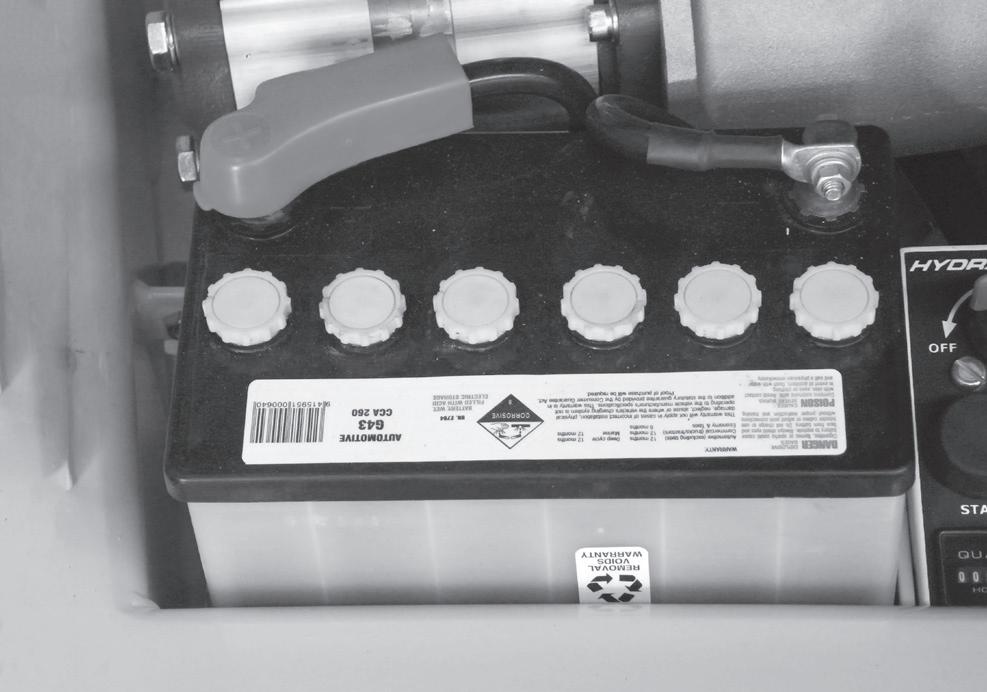
o Battery Terminals
Battery terminals should be tight, clean and free of dirt and corrosion. Any acidic buildup should be washed away with hot water and the terminals coated in a protective coating or grease.
o Battery Electrolyte Level
Remove the caps from the battery and visually check to see that the battery fluid is just covering the separator plates in the cells. The cells can be topped up with distilled water, or a tap with very clean water.
“F Mark
WARNING
DO NOT smoke or permit open flames or sparks when checking batteries. Batteries emit hydrogen and oxygen, elements that can combine explosively.
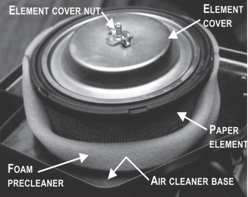
o Engine Air Cleaner
Check for build up of dirt and debris on the filter elements, as well as on the grass screen on the front of the crankshaft.
See “Servicing” chapter 11 for correct cleaning/ replacement procedures.
• Always wear safety glasses when checking or adding to battery fluid level.
• Do not overfill the cells – the water should only just cover the plates.
Filler Cap
5. Daily Inspection and Maintenance
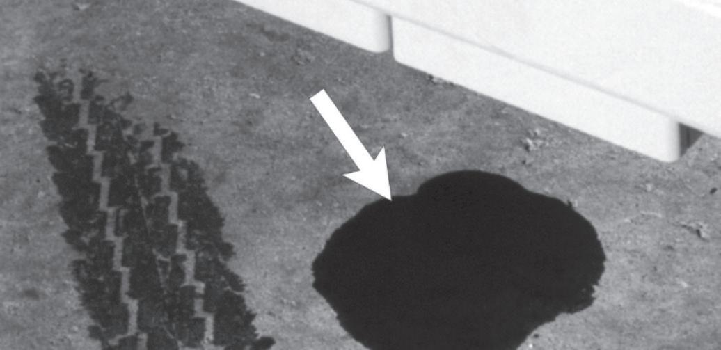
o Hydraulic Oil leaks
Hydraulic oil leaks are easily visible and can show up any place.
Visually inspect the entire EWP for hydraulic oil leaks. Check the ground under the EWP for leaked oil.
Carefully inspect the exposed hydraulic hoses for signs of leaking hydraulic oil or obviously loose fittings.
DAN G E R
Never search for Hydraulic leaks with your hand - use a piece of board.
High pressure oil will puncture your skin and enter your bloodstream, resulting in death or amputation in a very short time.
DAN G E R
Leaking hydraulic oil can cause burns, fires, falls (slipping), cuts, and puncture wounds (if under high pressure). Have a qualified trained maintenance person repair all hydraulic fluid leaks before you operate a Hydralada EWP.
o Structural Damage
Visually inspect the entire EWP for deformity, cracks, dents or anything unusual.
Inspect for cracks or damage.
Clean the Work Platform daily before beginning operations.
Check all retaining fasteners are fitted and tight.
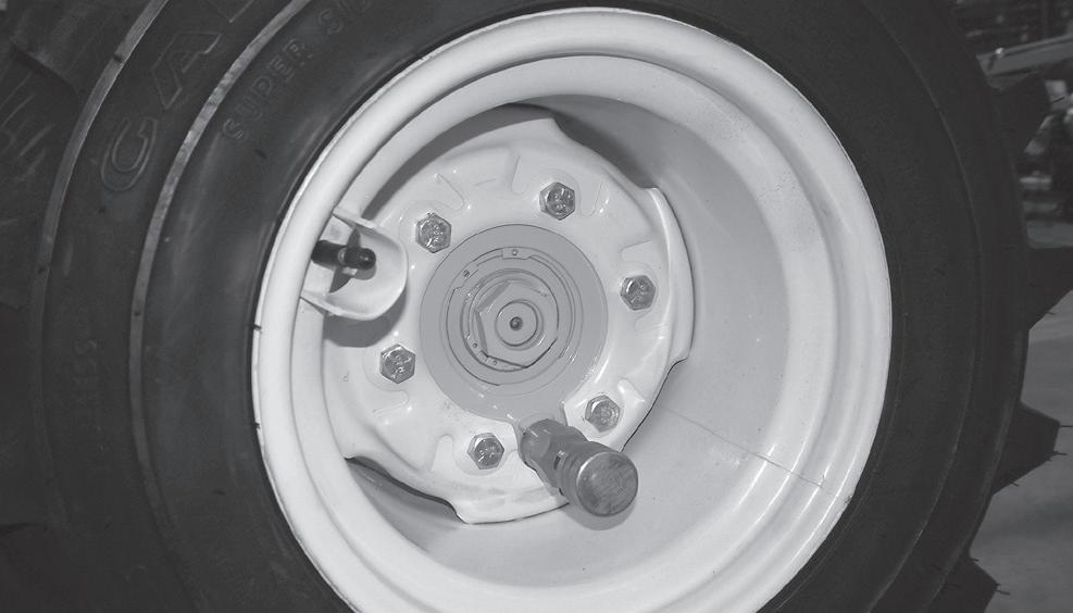
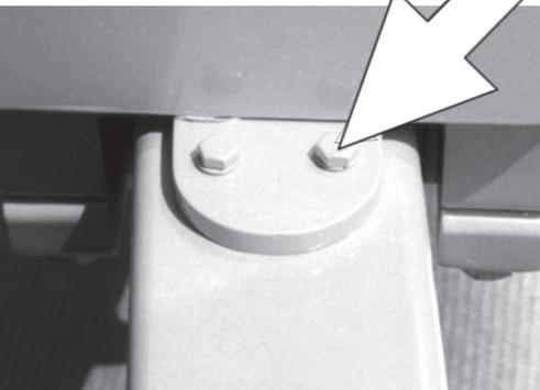
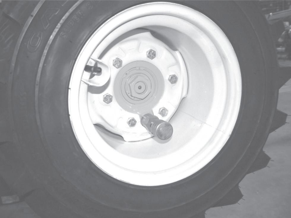
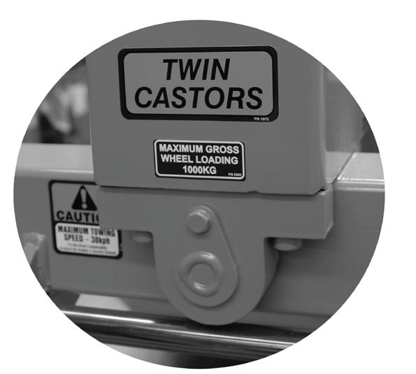
o Wheel Nuts
Pay particular attention to all of the wheel nuts/ bolts. None should be visibly loose, missing, or deformed.
Tension five stud rims to 60 ft/lbs, and six stud rims to 85 ft/lbs. DO NOT over-tension as this can distort the wheel rim.
Problems with wheel nuts continually coming loose are usually the result of damage to the tapers in the rim, as well as the nuts. This damage can only be caused by running the EWP with the nuts loose.
DAN G E R
Never use an EWP unless any problems with wheel nuts are properly resolved as the stability of the EWP relies entirely on the wheels.
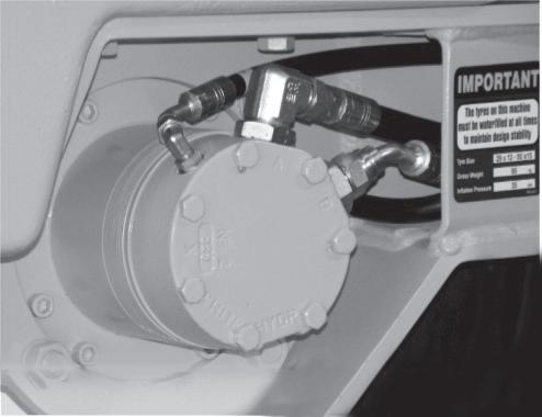
o Wheels and Tyres
The tyres on the Hydralada EWP are water-filled to provide ballast and form vital part of the Elevating Work Platforms stability.
If the EWP is being operated in areas where the day time temperatures are less than 1C, the ballast liquid will need to include antifreeze. Alternatively, the wheels can be foam filled. Call a local tyre specialist, or call the Hydralada Service department free-phone for advice.
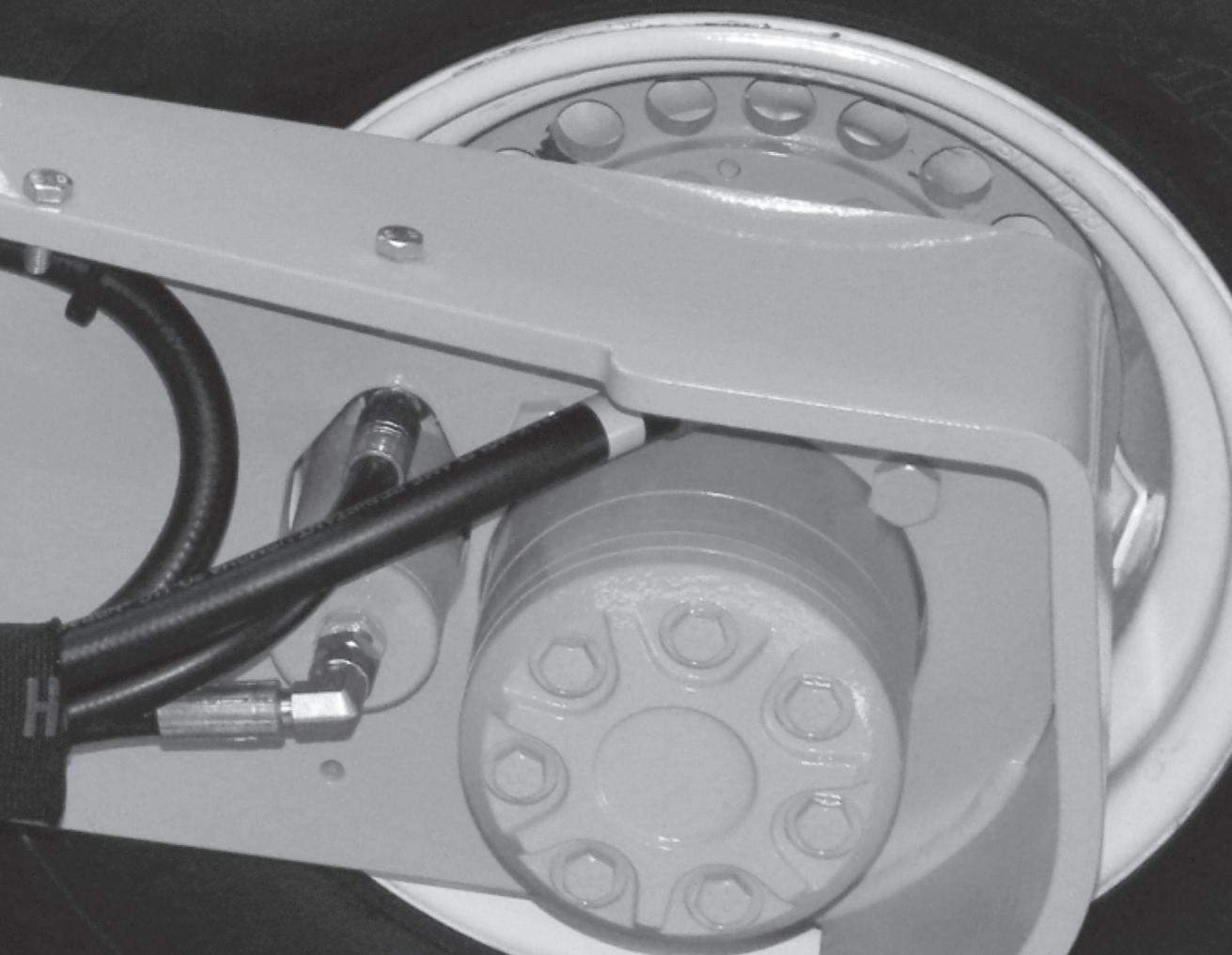
HUB AND WHEEL NUTS
Hub Nut
Six Wheel Nuts
5. Daily Inspection and Maintenance
• Check each tyre for obvious damage that could cause a blowout.
• Ensure they are filled to the required level with a suitable liquid.
• Check the pressures using a suitable tyre gauge. The wheel must be positioned with the valve at its highest position.
• The recommended pressures are set out in the ‘Specifications’ chapter 1 and the ‘Servicing’ chapter 11 of this manual.
• If the tires are repaired or serviced in any way, they must be ballasted to reach the tare weight as set out in the ‘Specifications’ chapter 1 of this manual.
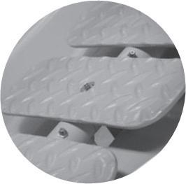
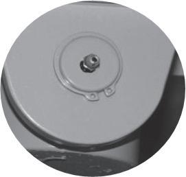
o Bolts and Fasteners
Visually inspect all bolts and fasteners to see that none are missing or obviously loose.
When checking the wheels, always watch the hub nut for any indication of movement. If there are any concerns with this item, it will be necessary to call a qualified Hydralada service technician as these require special equipment to service.
o
The tyre pressures on the Hydralada EWP must be maintained at the correct level. Uneven pressures will cause the EWP to drive to one side, instead of in a straight line. High inflation pressures deliver poor traction, and impair the tyres ability to clear the treads. Low inflation pressures result in damage to the tyre side walls, and affect the stability of the EWP on slopes.
o Lanyards and Safety Harnesses
Check with your local regulatory authority for their specific requirements concerning lanyards and safety harnesses.
Visually check the lanyard anchor points to see that they are not deformed, damaged or cut off.
Visually inspect the condition of lanyards and safety harnesses being used for cuts or damage.
Electrical System Fuses
These are mounted behind the engine under the right hand side bonnet, or under the left hand bonnect for Diesel powered Elevating Work Platforms. If there are problems with any of the electrical functions, check the condition of the fuses for the circuit. They protect all the electrical circuits in the event of an electrical overload or short circuit.
It is important that only the correct fuses as shown on the chart are used in the respective positions.
5. Daily Inspection and Maintenance
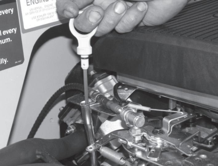
o Inclinometer
Hydralada Elevating Work Platforms are fitted with Alarms which become active once the EWP is raised out of the transport position. To check the operation, proceed as follows;
• Turn on the Master Battery Isolator Switch.
• Turn on the Ignition Switch and the Alarm will sound one beep.
• Start the engine, and operate the ground station manual control movement lever (see Section 7) to fully raise the boom.
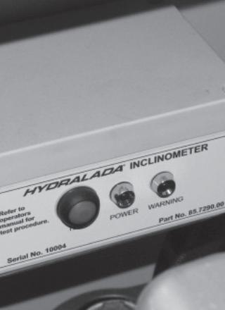
• Check the operation of the Inclinometer by pressing the red Inclinometer Test Button (as shown in the picture below).
• When the Inclinometer Test Button is activated the Alarm should sound and the Warning LED will flash.
This procedure confirms the system is operating correctly and that it will sound the alarm automatically if the inclination of the EWP reaches the maximum rated inclination. If the EWP is fitted with more than one Inclinometer, carry out the above procedure for both units.
If the Inclinometer in any way does not perform or respond as stated above, the EWP must not be operated. The EWP must be immobilised by removing the Battery Isolator switch key until the issue is rectified by a Qualified Hydralada Service Technician.
o Rotating Beacon (option)
Visually check the optional rotating beacon, to see that it is functioning when the EWP is turned on.
The beacon switch by the hour meter must also be turned on (see page 4-5 ).
o Switched Mid-rail
Check the operation of the mid-rail to ensure it is not bent or distorted in any way. Once the mid-rail is lifted from its operating position, the engine should not run, and the starter should be deactivated.
o Work Platform Controls (Maxi 750 Models Only)
Check each of the controls to ensure that they are functioning correctly.
• Cycle each of the boom lift, tele and slew functions through their complete range of movements, checking for any indications of structural problems relating to the bearings and load bearing assemblies.
• The inner boom should be clean and lightly lubricated with silicone spray.
• All the pivot pins should be in place held securely by their retaining bolts and circlips.
• All hydraulic hoses should be undamaged and show no indication of leaking.
• The grease nipples on the pins must be undamaged.
• Check that the greasing schedule is being kept up to date.
• The engine must shut down when the midrail is lifted.
PLATFORM SWITCHED MID-RAIL
Inclinometer Test Button
5. Daily Inspection and Maintenance
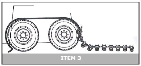
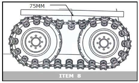
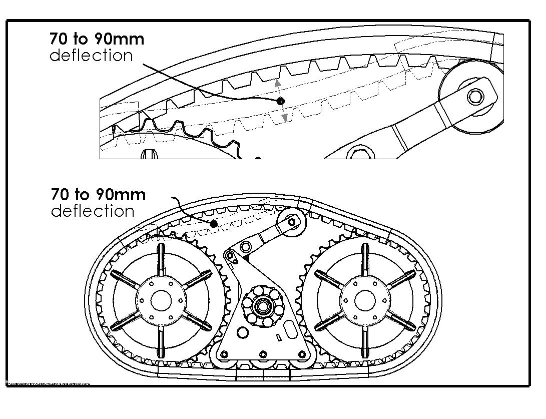
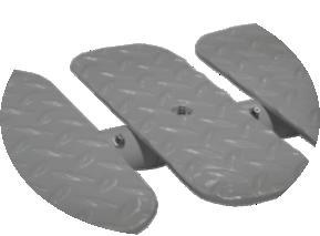
o Steel Tracks (option) Fitting Tracks
1. Check the tyres are inflated to the maximum pressure (12psi).
2. Unroll the track in front of the wheels so the side plates are touching the ground. Lift the end up onto the tyre.
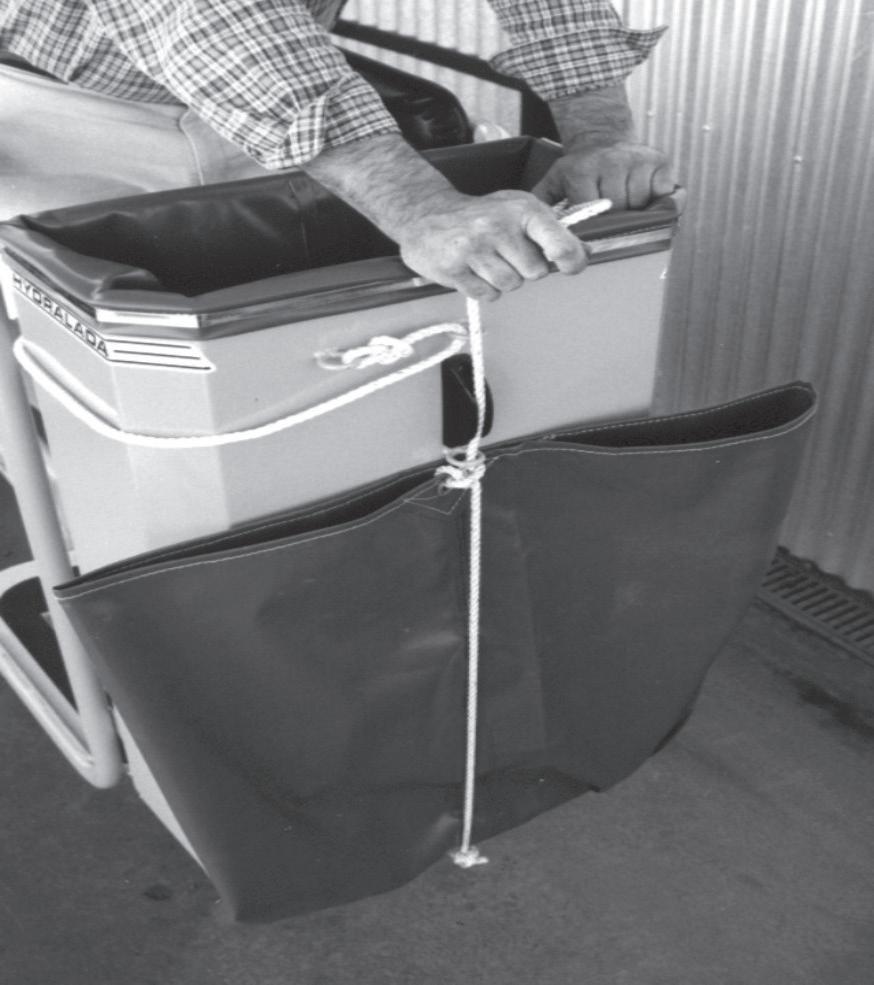
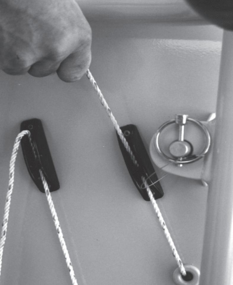
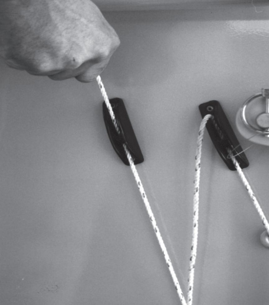
3. Connect a rope onto the end and lead this across the top of the wheels and down the back, and tuck it under the rear tyre.
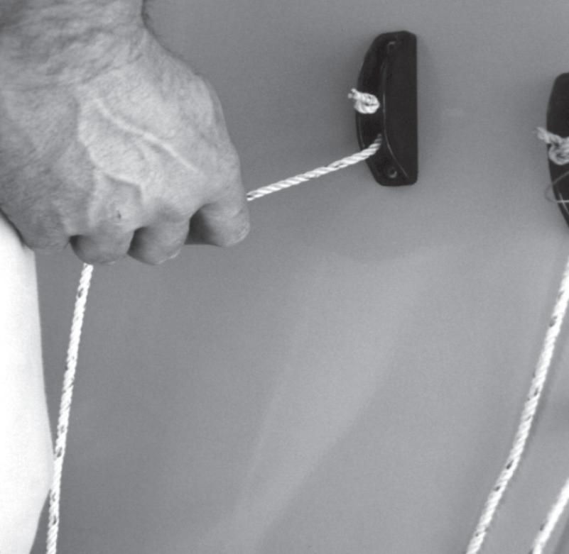
4. Carefullly reverse the machine, pulling the track across the top of the wheels and into position.
5. Once the two ends of the track come close, chain or tie the two ends together, and continue to move the machine until the two ends are positioned centrally over the top of the two wheels.
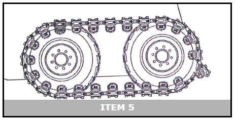
6. An installation tool is provided with every set of tracks. Mount this as shown in the illustration, and pull the two ends together. It may be necessary to carefully move the machine back and forward a little to settle the tracks into position.
CAUTION
Do not use a lever longer than 400mm to pull the track ends together. Excessive force can damage the installation tool, and result in personal injury.
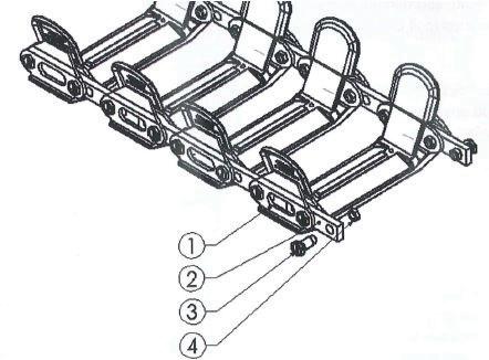
7. Install the Duro-pins to join the track, and torque the Duro-pin nuts to 80ft/lbs.
8. Drive the machine a little and check the tension of the tracks. They should operate with around a 75mm sag between the two wheels. Operating the tracks too tight uses a significant amount of driving power as well as overloading the bearings in the hydraulic wheel motors.
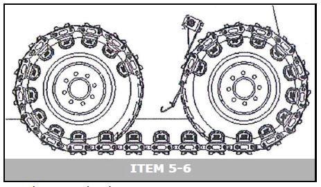
Adjusting the Track Tension
Each link has two holes which can be used to connect to the next link. If the tension becomes too loose, a link can be released and the track pulled up to the next hole. Once all the links are pulled up to the second hole, it will be necessary to inspect and replace the Duro-pins which are worn.
1. Track Pad
2. Track Link
3. Dura Pin
4. Jam Nut
5. Daily Inspection and Maintenance
across the top of the wheels and into position.
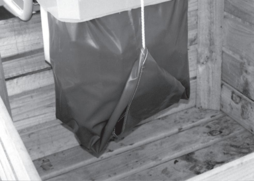
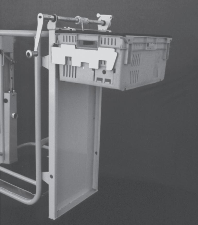
o Irrigated Pick Bag
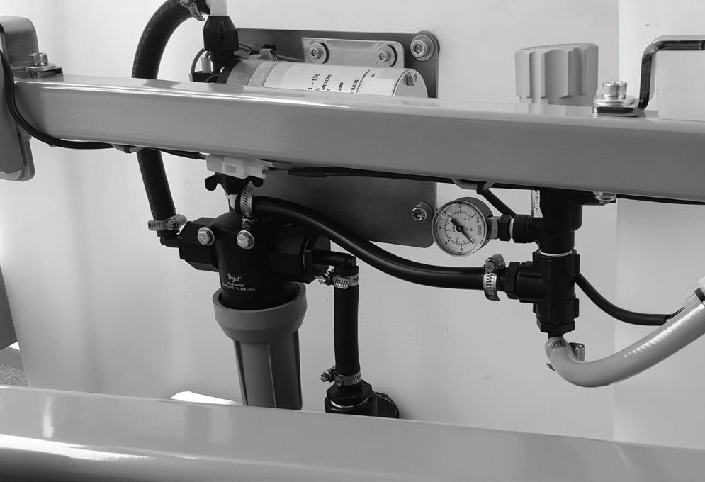
Product System Filter
This filter should be removed and checked at least once a day. If the product includes an excessive volume of solid matter, it may need to be cleaned at more frequent intervals.
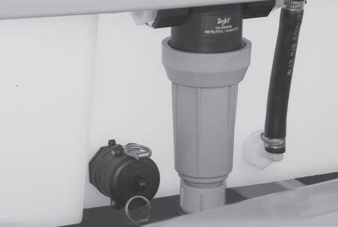
The filter can be flushed by removing the cap at the base of the bowl while the tank level is above the filter. However this may not be completely effective if the filter is plugged, meaning the element will need to be removed and cleaned.
To do this, the level in the product tank should be below the level of the filter. Proceed by unscrewing the plastic filter bowl assembly off of the base. This enables you to remove the plastic filter element for cleaning.
The element should be cleaned using a standard water hose. Never use hard brushes or high pressure washing systems on this component.
If the gauze is punctured in any way, it must be
replaced with a new part.
Nozzle Assembly
The operation of this should be checked daily to ensure the nozzles are spraying correctly and are not blocked in any way.
It is also important to ensure the mounting has not been bent in any way which could result in the
spray pattern not covering the entire surface of the picking bag.
Pressure Regulator
With the system operating normally, the regulator should be set to 1.0 Bar. Operating at higher pressures will overload the Electric Product Pump, as well as using too much product.
Continuing to operate the system with a blocked filter will result in serious damage to the electric pump.
WASH TANK AND PUMP ASSEMBLY
6. Operation
n Operating Procedures
This Chapter explains how to properly start and operate a Hydralada EWP. Read and understand all the previous chapters in this manual before you begin to operate a Hydralada EWP.
NOTE
Be especially sure that you are familiar with the ‘Safety’ Chapter. Review it now if it is some time since you read it. It may save you from serious injury or death.
DAN G E R
The Hydralada EWP is NOT ELECTRICALLY INSULATED. Never approach to within 4 Metres of any Overhead Power cable or line. Death or Serious Injury to operating personnel, can occur if the EWP should come into contact with energised electrical wires during the operation. DO NOT attempt to operate the EWP controls if the platform, boom, or any other conducting part of the machine is in contact with energised electrical wires or if there is an immediate danger of such contact.
DAN G E R
The Operator, or any of the people involved with the operation of the Hydralada EWP, must not be under the influence of alcohol or drugs of any kind.
o Preparing for Operation
Before beginning to operate the Hydralada EWP the Operator must:
• Perform the ‘Daily Inspection’ as described in chapter 5 of this manual, and arrange to have any maintenance as described in chapter 11 of this manual carried out as necessary.
• Before beginning to operate the EWP, the Operator must check the work area, and identify any hazards such as uneven ground, overhead wires, or other obstructions.
• If the EWP is to be operated on any slope, the gradient must be measured before operating the machine on the area. Refer to Page 6-7. The safe working angle is different for every EWP depending on it‘s specification. Check the decal on the rear of the Work Platform for the maximum incline rating of the EWP. Alternatively, this information is shown on the stability certificate belonging to the EWP you are operating which is included in the delivery manual of the machine. If in doubt contact Hydralada Company quoting the serial number of your EWP for the appropriate information and advice.
• Check the Maximum Rated Capacity for the platform, and ensure this weight is not exceeded.
• The Operator must wear appropriate clothing and PPE. To be able to operate the pedals effectively, it is particularly important to wear sturdy footwear.
• Before starting the engine, the Operator/s must connect their safety harness to the certified anchor point provided under the top rail of the Hydralada work platform.
TURN ON BATTERY ISOLATING SWITCH
6. Operation
o Starting the Engine
To start the engine from cold proceed as follows:
1. Check that the Switched Mid-rail on the platform is fully closed.
2. Turn the Ignition Switch in the Work Platform to the ON (RUN) position. For Maxi 750 model EWP’s release the platform control panel emergency stop button into the run position.
3. Set Throttle Control down the gate approximately 25mm (1”).
4. Turn the Battery Isolating switch fully clockwise to the ON position.
5. Check that the emergency stop switch in the engine bay is in the NORMAL (RUN) position.
6. Move the Choke Control to the closed position (CH23S Engine).
7. Press the engine bay Starter Button. Hold it there until the engine starts or for a maximum time of 10 seconds.
8. When the engine starts release the starter button (7) and open the choke control (6) as the engine begins to run smoothly.
9. When starting the engine in ambient temperatures of less than 12C avoid running the engine at maximum RPM‘s until the temperature of the hydraulic oil has reached approximately 50C.
The engine should now be running, and the Hydralada EWP is ready to begin work. The engine must be shut down using the switch at the rear of the platform, before entering the Work Platform, and restarting the engine.
6. Operation
o Starting a Warm Engine
Once the engine is already warm it can be started from the operators position in the Work Platform without needing to use the choke.
o Starting a Fuel Injected Engine
These engines have no choke control as described on the previous page, but otherwise the start-up procedure remains the same.
A Warning light is mounted near the top of EFI engines to alert the operator of any malfunctions in the electronic systems.
Normally this light will not activate. If it does, shut down the engine and call a Service technician.
CAUTION
If the engine develops sufficient speed to disengage the starter but does not keep running (a false start), the engine rotation must be allowed to come to a COMPLETE STOP before attempting to restart the engine.
If the starter is engaged while the flywheel is rotating, the starter pinion and flywheel ring gear may clash resulting in damage to the starter.
To enter the Work Platform stand beside it, and raise your head and shoulders up into the Work Platform until you are standing upright. Now raise your feet into the Work Platform, taking care to only step onto the outer areas of the Work Platform floor.
IMPORTANT
If the starter does not turn the engine over, release the starter button IMMEDIATELY. DO NOT make further attempts to start the engine until the condition is corrected.
CAUTION
If the engine does not start in 10 seconds release the starter button. Wait 60 seconds for the starter motor to cool down before trying to restart the engine again. Continual cranking of the starter motor will only result in its damage and may burn out the starter motor.
A metallic ticking may occur when the engine is first started. This is usually caused by a hydraulic lifter being stuck down during storage. Run the engine for 5 minutes. The noise will normally cease in the first minute. If the noise continues, run the engine at mid throttle for 20 minutes. If the noise persists, contact your Hydralada dealer.
NOTE
The engine should already be running (as described earlier in this chapter) before you start this section. Hydralada Company offers a wide range of controls and combinations of those controls. You may have foot controls, hand controls or a combination of foot and hand controls. To simplify the process this part of the chapter describes driving with Foot Controls first, then describes driving with Hand Controls.
6. Operation
Driving the Hydralada Ewp
Enter the platform, close the mid-rail, and attach the lanyard of your safety harness to the anchor point provided.
o Operating the Throttle
There are three main positions for the Throttle Control:
THROTTLE CONTROL – FULLY RAISED IN THE IDLE POSITION
1st. Fully Raised To Top Of Gate:
This is the idle position and does not provide any governor response. As any load on the engine causes the rpm to drop, this position is sometimes used to raise the Work Platform very gently.
2nd. Partially Down The Gate:
(Approximately 1” - 25mm)
When the control is in this position, the governor springs are tensioned without increasing the engine RPM appreciably. On this setting the governor provides a quick response to any increased load, making this the preferred working setting.
Running the engine too slow causes the compression release to activate and generate a loud ticking noise. Running the engine at this speed will cause serious damage to the engine.
3rd. Lower Down The Gate:
This provides a range of higher speeds and is used when driving the EWP, between jobs, with the Work Platform down.
NOTE
The controls are progressive which allows the operator to ease the EWP slowly in any direction by “feathering” the pedals.
o To Operate the EWP
1. Move the throttle control partially down the gate until the engine just begins to increase in speed as described in the previous paragraph.
2. Facing forward, with the machine behind you, operate both drive controls in the forward direction to drive forward .
3. To reverse operate both controls in the reverse direction.
4. Operate the lift control to lift the Work Platform, which can be elevated safely until it reaches full elevation. Operating the lift control in the opposite direction will lower the Work Platform.
If the lift pedal stops are set correctly, lowering will require a slight force on the control. The descent speed is easily controlled by varying the pressure you apply to this control.
CAUTION
Be certain that the space into which you are about to move the platform, boom and/or chassis is free of obstructions.
ALWAYS look in the direction of movement. Be sure that the lanyard of your fall restraint is attached to the anchor point on the platform mount.
6. Operation
o Turning Techniques - Pedals
1. When driving at LOW ENGINE SPEEDS turns are made by using a double wheel turn. Because it is not necessary to ‘feather’ these turns, the operator is able to stand on the pedals or the surrounding platform. Operating one wheel forward and the other backwards simultaneously turns the EWP ‘on the spot’.
Using both wheels to make a turn doubles the speed of the turn, meaning that good productivity can be achieved, even at low engine rpm‘s.
CAUTION
2. When driving at HIGH ENGINE SPEEDS turns are made by slowing a single wheel. By standing on the side plate beside the control pedal the operator is able to use the side of his/her foot to ‘feather’ the control and make a smooth turn.
Because the speed of only one wheel is being changed, these turns, even at high engine rpm‘s can be quite gentle. However, single wheel turns are not very productive when the EWP is working.
3. Now practice driving the EWP using both turning techniques until you are totally comfortable with both turning concepts.
4. Finally, begin to drive the EWP using various combinations of lift and driving functions. Take particular note of the effect of setting the throttle in the correct position to ensure good governor response without increasing engine rpm‘s.
CAUTION
o Other Control Options
While these instructions are for the operation of a standard Hydralada EWP which is fitted with three pedal controls, they also apply to Elevating Work Platforms supplied with other control options. The two most important are T Bar hand controls and Six Pedal controls which are shown in the illustrations below.
To make a smooth turn at higher speeds when driving a machine fitted with the hand control option, use the grab handle to steady your hand. Use your fingers to operate the drive levers.
OPERATOR USING THE HANDREST TO STEADY THE HAND
HAND CONTROLS
SIX PEDAL WORK PLATFORM
The stops on the Drive Controls are preset and MUST NOT be altered by the operator.
Do not attempt to make a high speed turn when standing on the pedals.
6. Operation
n Common Problems Encountered by New Operators
o Not Driving Straight
This is caused by one of two basic reasons:
1. The wheels are not rotating at the same speed.
2. The rolling radius of the wheels is not even.
• Drive the EWP in the opposite direction on the same ground and see that it still veers off to the same side.
• Remember that when driving across a gentle slope, the weight transfer to the downside drive wheel changes the rolling radius and will naturally cause the EWP to track down the slope.
• On steeper slopes the increased load improves the traction of the downside wheel, and can make the EWP tend to turn uphill.
• With a slew Work Platform machine the slew must always be in the straight ahead position when checking the tracking.
• Have a Hydralada technician check the settings of the pedal stops.
• Check the tyres on each drive wheel are equal. Odd size wheels mean the EWP will always track off in one direction.
• Check the tyre pressures with a gauge. Tyre pressures affect the rolling radius of the wheel assembly
o Rough or Jerky Operation
• Using too high engine rpm‘s. Using double wheel turns at low engine rpm‘s is often smoother.
• Incorrectly adjusted pedal stops.
• Using double wheel turns at high engine speeds.
• Be positive about where you want to take the Work Platform and operate the pedals confidently. This will probably need lower engine rpm‘s, but will often make the overall result smoother. This tends to come only with practice.
The advantage of using a double wheel turn technique when working is:
• The machine turns faster, and require less rpm‘s - less noise and fuel - to do so.
• Double wheel turns impose less mechanical stress on the machine
• Double wheel turns create less disturbance to the ground surface - this is especially important when using a Tandem Drive model.
• The machine is easier to drive with the Work Platform elevated as this moves the Work Platform above the axis of the turn, thus reducing the effect of throwing the operator sideways.
o Lack of Traction
If the tyre pressures are too high, the drive tyres will not deliver good traction. This can be particularly frustrating when working on slopes or in damp conditions.
In extreme conditions, it may be necessary to run these at their minimum pressure. Refer to the ‘Specifications’ chapter 1 of this manual for guidance on this matter.
Keep both wheels driving whenever possible. Keeping both wheels driving provides the power and traction to operate in these conditions with minimal loss of traction
WARNING
Beware of loose mulch under the driving wheels of the machine. The drive wheels can bury into this material quite quickly and cause potentially hazardous instability. This is particularly important when working in sloping areas.
CAUTION
DO NOT tamper with the governor setting to increase the maximum engine speed. Over-speed is hazardous and will void the engine warranty.
WARNING
If the inclinometer alarm begins to sound, lower the boom immediately before moving the machine towards an area of reduced incline
6. Operation
n Tips for Experienced Operators
Once you begin operating your Hydralada EWP in different operating environments, you will notice various characteristics which require a degree of understanding and skill to manage safely.
o
Assessing the Workplace
Before using the Hydralada EWP in any workplace it is important to check the area for hazards of any kind.
If the area includes sloping ground, it will be necessary to measure the degree of slope using an appropriate gauge, and comparing the result with the rated angle of your machine. The maximum slope your Hydralada EWP can be safely operated on in any direction is listed in degrees on the EWP serial number plate and also on the ‘stability chart’ which forms part of the delivery manual supplied with the machine.
Keep both wheels driving whenever possible. Keeping both wheels driving provides the power and traction to operate in these conditions with minimal loss of traction
o Hillside Restraint Model
This applies to Models Compact 300 and Hilift 360. For flat land operations (up to 5 degree slopes) these models are fitted standard with the Hillside Restraint system. This is hydraulic retardation (dynamic) brakes only. This prevents the wheel drive motors from losing barking effect during overrun traveling down a slope. When parked the machine may creep. If parked on a slope the drive wheels are required to be chocked to prevent the MEWP from creeping. Where the slopes exceed 5 degrees, the optional Hydrabrake failsafe brake system must be fitted. In no circumstances should the machine be operated on slopes greater than the Stability Rating specified in the Hydralada Delivery Manual.
o Measuring a Slope
Any slopes on areas where the Hydralada EWP is to be used should be measured carefully using a suitable slope meter to ensure no slopes exceed the rated capability of the EWP. In the case of twin castor models, neither the castor or the main driving wheels must be operated over this rating.
Where a slope meter is not available, slopes can be measured using a standard level and a suitable measuring device.
Taking a vertical measurement one metre horizontally out from the slope gives the percentage of the slope. Using the chart below, this can be converted into degrees which is the scale used by Hydralada Company.
o Working on Side Slopes
Even experienced operators need to be completely familiar with the EWP they are operating before beginning to work on sloping areas.
• Remember to always keep the tail of the EWP up the slope as much as possible.
• It is better to access the majority of the tree from the uphill side, leaving only a minimal amount to be accessed from the downhill side. This
SLOPE GAUGE
6. Operation
practice minimises the amount the EWP needs to be maneuvered in a tail down situation, where traction and control can be compromised.
• Remember that once an EWP is already positioned and stationary on a slope, simply lifting the platform height could bring the EWP into an unstable position.
DAN G E R
Never operate a machine fitted with Twin Castors with a wheel off the ground. The machines stability rating is void in this condition.
o Working Up or Down a Slope
• Never exceed the maximum rated capacity of the EWP.
• Always KEEP THE CASTOR WHEEL UP THE SLOPE. This keeps the machines weight over the driving wheels, and maintains traction and control at all times, even when operating in elevated positions.
• Drive the EWP up/down the row at low engine rpm‘s, using double wheel turns to move into the tree.
• Keeping both wheels driving provides the power and traction to operate in these conditions with minimal loss of traction.
• Sometimes when working from the lower end of the slope, the operator will need to move up the row in the Elevating Work Platforms reverse direction.
WARNING
Never over-fill the picking bag. This practice invariably means the Manufacturers rated capacity specifications have been exceeded which will make the machine unstable.
DAN G E R
When operating the Hydralada machine at high elevations on slopes, never use the machine with the Work Platform facing uphill.
DAN G E R
Maintain a minimum safe distance to energised power lines. See the “Electrical Hazard” section at the front of this manual for a complete explanation of the hazards concerning electricity.
DAN G E R
Never operated a Hydralada EWP when the combined weight of the Operator, the Picking bag, and its contents exceeds the machines rated maximum capacity
WARNING
If the inclinometer alarm begins to sound, lower the boom immediately before moving the EWP towards an area of reduced incline
When operating in extreme conditions, it is sometimes helpful to operate the tires at lower pressures than is listed on pages 1-1 and 11-8. This improves traction, as well as the tires ability to discard dirt from the tread. However there can be a risk of damaging the side walls of the tires if the EWP is to be operated on a side slope, or for prolonged periods.
6. Operation
n Boom Support
This boom stand can be set to support the boom when the EWP is being serviced or transported. It is not necessary to set this if the EWP is being transported with the boom fully lowered. This stand is available for purchase from Hydralada Company.
The boom support for Compact and Hi Lift models utilises the Drawbar Pin placed through the hole provided in the Chassis, as shown.
Raise the Boom, insert the pin and then gently lower the Boom to rest on the pin.
The Pin is stowed in the Castor Leg assembly.
n Transport
The Hydralada EWP is fitted with tie down points for when the machine needs to be transported.
The position of these are labelled on the machines as per the below diagram.
When transporting the Hydralada EWP, it must be securely fastened to the transport deck. It must be restrained in two opposite directions on both sides of the chassis to prevent it from moving.
Ensure before transport or towing, all attachments or loose items are removed or securely fastened to machine.
n Storage
When the Hydralada EWP is not in use, or is in storage, the Battery Isolating Switch must be turned off.
If the machine is to remain in storage for six months or longer:
1. The battery should be removed from the machine and its charge maintained by a monthly top up charge.
2. The fuel should be drained from the fuel tank. Hydralada Company have a weather proof Work Platform cover available to purchase for single man Work Platforms (Part Number 67-2763-00).
Compact and Hi Lift Models
Maxi Models
BOOM SUPPORT FOR MAXI MODELS
BOOM SUPPORT FOR COMPACT AND HI LIFT MODELS
7. Emergency Operation
n Safety Harnesses and Lanyards
DAN G E R
n Restraint Harnesses
A suitable Restraint harness must be worn by any person operating a Hydralada machine at all times. With even the best designed machine with all modern safety systems, an operator cannot be safe at height without using proper Personal Protective Equipment (PPE).
n Emergency Controls
O Emergency Stop Controls
These will completely stop the Hydralada EWP in the event of some emergency or problem by shutting down the engine and all systems.
o Base Level
A red switch is located in the right hand engine bay, and is normally in the down (RUN) position. In the event of an emergency move this switch up to the EMERGENCY STOP position marked on the decal.
This function is also provided by the Battery Isolating Switch. This is a red plastic key switch mounted at the left hand end of the small control panel under the engine bay bonnet of the EWP.
o In the Work Platform
The Emergency Stop Switch in the Work Platform is mounted within a rectangular guard behind the Work Platform and is part of the ignition switch assembly. Moving this switch up to the EMERGENCY STOP position shuts down the engine and all electrical functions.
If the Battery Isolating Switch is turned off the Emergency Crank function described on Page 7-2 will also be disabled.
7. Emergency Operation
o Ground Station Emergency Controls
Hydraulic Movement Controls
A manual control lever is mounted to the front of each Hydraulic control section. Operating any of these control levers with the engine running will activate the respective movement, overriding any other device on the EWP. When operating the boom control lever, the boom can be lowered, even when the engine is not running.
MOVEMENT CONTROLS
MACHINE MOVEMENTS
o Emergency Engine Crank
If the engine will not run for any reason, the EWP can still be moved by operating the respective manual movement control while simultaneously cranking the engine using this button.
The Emergency Engine Crank button remains active even when the Emergency Shut Down Control at either the Work Platform, or Engine Bay has been activated.
• The engine will not start if the Emergency Shut Down Controls at either the Work Platform, or the Engine under bonnet are activated.
• To crank the engine, the Plastic Key under the Engine bonnet must be in the ‘On’ position.
o Quick Release Pins
If the Work Platform control is jammed for any reason the clevis pins, which connect the control cables to the spool, can be removed by pulling the ring which is attached to each of them. This will enable persons at the Ground Station to manipulate the movements using the Manual Movement Control Levers. EMERGENCY ENGINE CRANK BUTTON
REMOVING THE QUICK RELEASE CLEVIS PIN
7. Emergency Operation
n Emergency Operation
o Electrical Hazards
The Industry Best Practice Guides in New Zealand, and the AS2550.10 Standard used in most States of Australia require operators working within 6.40 Metres of live overhead lines to be assisted by a dedicated spotter on the ground who is to warn the operator of any danger. Under no circumstances are any uninsulated Elevating Work Platforms allowed closer than 4 Metres of live overhead power lines.
The section on procedures to be followed in the vicinity of power lines in the Horticultural Industry Best Practice Document reads as follows:
3.2. Emergency procedures
If an H/MEWP comes into contact with overhead power lines or equipment, anyone in the H/MEWP at the time should remain there and warn any others in the vicinity to stay clear. If it is safe to do so, operate the controls to break contact.
If it is not safe to break contact, the safest course of action is to:
• call for assistance, warning all persons to keep well clear of the machine
• do nothing until the line is de-energised. If assistance is unavailable and electrical contact cannot be broken then leave the H/MEWP and:
• switch off the motor and, where applicable apply brakes
• remove any loose clothing
• climb to a point about one metre above the ground from where you can safely jump to the ground
• jump so that you clear the platform before any part of you touches the ground
• fall away from the H/MEWP and not towards it
• do not touch the H/MEWP until the lines are deenergised.
3.3. Electrical industry safety information
Additional guidance on safe use of mobile plant in the vicinity of power lines is available at the Electricity Engineers Association’s (EEA) website at www.eea.co.nz.
H/MEWP = Horticultural/Mobile Elevating Work Platforms
o Instability and Loss of Control
In an Emergency situation, arising as the result of instability or loss of control, the first reaction of the Operator should always be to reduce the elevation of the Work Platform. Any reduction of the Work Platform elevation will immediately make a substantial improvement to the stability of the EWP.
o Incapacitated Operator
If the operator becomes incapacitated, the machine can be shut down from the ground by turning off either the Emergency Stop Switch, or the Elevating Work Platforms Master Switch. In this condition, the Work Platform can be lowered by operating the emergency lowering control situated under the Left Hand Bonnet.
o Mechanical Failure
In the event of a mechanical failure, leave the engine running, and lower the Work Platform to the ground. If the failure is of systems to support the Work Platform, this descent will still be controllable, providing the ignition switch is still in the run position. If the failure is of the drive system, the brakes will continue to be applied.
All Hydralada Elevating Work Platforms are designed and constructed to very exacting standards of technical excellence. Provided it is used by fully trained operators who are familiar with all safety procedures, and operate the machine within its design specifications, the procedures outlined in this chapter are unlikely to be needed.
o Rescue of Other Persons
Any operation of this nature must always be done within the design parameters of the EWP. The maximum rated capacity is particularly important as the normal Hydralada EWP is not designed to carry more than one person in the platform.
8. Picking Bag Operation
—IMPORTANT—
o Setup
Before using the bag it is important to ensure the following.
1. Check the condition of the liner and the foam lining of the steel case. These MUST be free of rips and damage.
2. Check the condition of the Draw-cords and Jam Cleats. The rope MUST NOT be frayed and MUST engage the teeth in the cleat securely. It is IMPORTANT to use only genuine rope as the “Lay” of these ropes must match the shape of the cleats properly to avoid slippage.
3. Check the condition of the Main-cord. The same factors apply as described above. The knot on the liner MUST be positioned so that when the door is fully closed the liner is pulled up to the level of the eye on the front of the bag.
o Operation
1. Straighten the liner before using the Main-cord at the front of the bag to pull the door closed, bringing the lip of the liner up to the small main-cord eye. Loop this cord around the top of the bag to secure it in case it is inadvertently released it from the Jam cleat.
2. Pull the top Draw cord to close the bag. This must be pulled very firmly to tension the liner. It is sometimes helpful to pull the cord between the bag and the top bar of the Work Platform to gain a more direct pull.
3. Close the bottom Draw-cord in the same manner. The bag is now closed and ready for picking. These procedures ensure that the liner is taught with no loose tucks which obstruct the flow of fruit through the bag. Having the fruit flow easily through the bag is necessary to avoid bruising.
8. Picking Bag Operation
4. Pick the top section full. Release the top Drawcord slowly, allowing the fruit to flow to the level of the second Draw-cord. Pull the rope through the cleat to the knot to avoid forming a choke point.
5. Pick the bag full and repeat the process again, allowing the fruit to flow to the bottom of the bag.
DAN G E R
IN ANY CIRCUMSTANCES NEVER overfill the picking bag by releasing the Main-cord to increase the capacity of the bag. This practice results in damage to fruit, and usually means the maximum rated capacity is exceeded which comprises many safety factors.
7. Bring the EWP over the bin. Release the Maincord slowly lowering the chute laden with fruit down to the floor level of the bin. It may be necessary to adjust the height of the boom to avoid free falling the product, or crushing it where the height is too low.
6. Finally pick the bag full.
PICK THE BAG FULL
PICK THE BAG FULL
8. Picking Bag Operation
8. Once the Main-cord is fully released the liner can be pulled up through the bag to release the fruit into the bin.
9. With the throttle at the low idle position the Work Platform can be lifted slowly to help complete the operation.
o Irrigated Pick Bag
This is used following exactly the same procedures as the standard pick bag.
The watering system must be kept operating at all times to avoid sap damage to susceptible fruits.
The system operating pressure should be adjusted to 1.0 Bar. Using excessive pressure increases the amount of product being used without improving the performance of the system in any way.
If there are problems with maintaining the pressure, check the condition of the filter. The service interval for the filter maintenance will need to be determined at each location as this depends mainly on the condition of the water being used.
Never over-fill the picking bag. This practice invariably means the Manufacturers rated capacity specifications have been exceeded which will make the machine unstable.
If you have any problems contact your local Hydralada dealer or Hydralada Company for assistance!
Drive carefully to avoid branches protruding into operators platform cage.
PULL THE LINER UP THROUGH THE BAG
8. Picking Bag Operation
o Maintaining the Filter
The filter bowl should be flushed regularly by removing the cap from the bottom of the bowl. To clean the filter properly, remove the filter element, the complete filter bowl assembly can be unscrewed, and the element removed for proper cleaning. If the element is damaged in any way, it should be replaced.
PRODUCT FILTER
Filter bowl assembly
Filter bowl cap
Tank Drain
9. Options
o Free Wheel Hubs
These allow the operator to disconnect the drive to the wheels to allow the EWP to be towed between jobs.
All drive wheels must be latched out before the EWP can be towed. To latch the drive pins out, first connect the EWP to the towing vehicle by using the approved drawbar, then withdraw each pin, and latch them out by turning each pin a ¼ turn.
To re-engage the drive, reverse the procedure and operate the wheel motors gently until the pins engage. Ensure all drive pins are securely engaged before operating the EWP.
CAUTION
When towing, always ensure the Hydralada EWP is connected securely to the towing vehicle using the approved draw bar. Never exceed 30 kph when towing.
o Twin Castors
These are 185 x 14 wheels mounted on an oscillating beam and increase the machines stability.
o Tandem Drive
This drive is supplied standard with Hydrabrake and is designed for maximum traction and extra stability. The EWP is operated in the same manner as a standard EWP.
The condition of the Brake Disc and its operating pin should be inspected regularly for excessive wear. If these components become worn, they should be replaced with new parts from your Hydralada Dealer.
Never operate an EWP, fitted with Twin Castors, with a wheel off the ground. The machines stability rating is void in this condition.
Any scuffing effect on loose surfaces can be minimised by using double wheel turns wherever possible.
FREE WHEEL HUB PIN
TWIN CASTOR OPTION
TANDEM DRIVE WHEELS
o Dual Castors
DUAL CASTOR OPTION
9. Options
o Rubber Tracks
Check the condition of the track belts and rollers. The track belts should be tensioned so that the track deflection is 70-90mm in the position of the arrow as shown in the below drawing
DAN G E R
Use care when the machine is on slopes that the offsetting effect of the Slew Work Platform is appropriate for the slope.
o Slew Work Platform
Hydralada Company offer the slew option which makes it easier to manoeuvre the work platform amongst branches.
o Crate Magazine
Adjustable for various brands of crates. This will handle up to four crates and is usually used in conjunction with a Rear Crate Frame.
o Picking Bag
This is a lynch pin type of mounting. It features a flared body and is fully lined with foam rubber and heavy duty PVC liner. See “Pick Bag Operation” chapter 8 for operating instructions.
SLEW WORK PLATFORM MODEL
PICKING BAG
9. Options
o Slope Gauge
A hand held instrument for measuring the degree of slope to assist in the safe operation of EWP. This is available from the Hydralada Company Spare Parts Department (PN 60-2797-00).
o Two Man Platform
o Rotating Beacon
This orange beacon is mounted on the tail of the EWP. Rotating beacons are fitted where the EWP will be used near vehicular traffic.
o Dual Outlets with Selector Lever
This allows two tools to be connected to the EWP simultaneously and includes a selector lever to direct the oil to either tool.
The oil flow can be controlled by the Series II Loppa by connecting to the plug provided, or delivered as a constant flow by switching the selector and activating the constant pumping switch.
G E R
If the Constant Pumping switch is activated while a Series II Loppa is connected, the jaws will close and the system will be overloaded. This could result in serious injury or death.
The pressure provided from this outlet is controlled by the machines main system relief settings to deliver 2000 psi. Check the pressure rating of your equipment before connecting to these outlets.
o Hydrafork
9. Options
o Auxiliary Hydraulic Outlet Option
The control switch is mounted behind the operator inside the Work Platform.
The standard hydraulic tool flow and pressure (20 L/pm at 2000 psi) is delivered at around 2000 engine rpm. Increasing the engine rpm will not increase this flow or pressure.
DAN G E R
Be aware of the dangers of working with high pressure oil. It can be almost invisible escaping from a pinhole, and penetrate the skin into the body. If fluid penetrates the skin, even if no pain is felt, a serious emergency already exists.
o Dual Power
The Dual Power option has a triple hydraulic pump which provides an individual pump for each function, LH wheel drive, RH wheel drive and boom lift.
When the boom is in the transport position, the Dual Power system is activated to increase the hydraulic oil flow to the wheel drive motors providing a faster travel speed for transport.
A switch located on the rear of the work platform allows the operator to turn this system off or on. The boom cannot be raised simultaneously with the drive wheels whilst in high speed travel mode.
o Auxiliary Oil Cooler
The oil cooler radiator and fan decreases the temperature of the hydraulic oil being returned from the platform.
9. Options
o Adjusta Trac
How to decrease and increase the width of the adjustable track option on a Hydralada EWP:
1. Park the machine on level ground and on a firm surface. Dismount the jack from it’s storage position on the inside of the right hand chassis leg.
2. Position the jack on the mount bracket on the side of the machine to be adjusted and insert the locator pin. Carefully jack one side of the machine so the wheels are clear of the ground.
3. Loosen the four chassis bolts to half undone using a 3/4 inch socket and strong bar. Disengage the quick release positioning pin (you may have to adjust the leg extension fore and aft to release tension on the quick release locking pin).
4. Fit a strong bar with a 3/4 inch socket and adjust the leg out until the quick release locating pin locks in to the outer position. Ensure pin locks fully. Check that the hydraulic hoses are lying in the correct position and are not snagged.
5. Ensure the quick release locking pin is fully engaged. Re-tighten the clamp bolts to 80ft/ lbs torque. Lower machine and re-stow the lifting jack. Repeat process on the opposite side of the machine.
6. Carry out the above procedure to retract the leg extension. When retracting the leg watch the hydraulic hoses closely to ensure that they track correctly to their normal position and do not snag. Ensure clamp bolts are done up to the specified torque and the locating pins are fully engaged.
Chassis Bolts
Chassis Bolts
Quick Release Locking Pin
Chassis Bolts
Chassis Bolts
Quick Release Locking Pin
10. Troubleshooting
o Troubleshooting
A number of the actions described in this chapter may be performed by a Hydralada EWP operator. A trained and qualified service technician is not necessarily required.
o Engine Fault Diagnosis Flow Chart
Engine cranks but will not start
No fuel in the tank
Carburetor is flooded
Remove the sparkplug and dry, fully open the throttle and crank the engine till it starts
CAUTION
Any problem that cannot be fixed by actions listed below should be referred to a trained and qualified Hydralada EWP service technician.
Starter problem No reaction to starter switch
Engine cranks slowly and will not start Flat
battery
Dirty battery terminals Charging system fault Faulty ignition switch
Engine starts but runs poorly
Faulty ignition switch Multi plug or Wiring loom Switched Midrail may be open
Faulty starter (possibly noisey)
Choke not fully open
Persistant backfiring
No fuel in the carburetor
Fuel tap turned off Blocked filter Faulty fuel pump No spark
Fault in the ignition switch Multiplug Ignition module
Stale or contaminated fuel
EFI
(Check Battery Volts 12v)
Clean fuel system, carburettor, and replace fuel filter
Swap the motor supply hoses at the outlet of the control valve
Problem changes to other wheel motor
Return hoses to their original position Control valve ok
Swap hoses at the outlet of the control blocks
Problem swaps to other side
Fau
Fau Lt i N hYDrau Lic P u MP
10. Troubleshooting
11. Servicing
o Engine Identification Numbers
KOHLER ENGINE
o Engine Oil
When ordering parts, or in any communication involving an engine always give the Model, Specification, and Serial Numbers of the engine. The engine identification numbers appear on the decal (or decals) affixed to the engine shrouding. Include letter suffixes, if there are any.
Record your engine identification numbers on the identification label below for future reference.
For details of machine/identification numbers and codes see the “Introduction”.
The engine is covered by a Kohler warranty for the first two years. Engine warranty service under the terms of the standard Kohler warranty can be obtained by presenting the engine to any authorised Kohler Service Centre.
MODEL NUMBER:
SPEC NUMBER:
DISPL (CC):
SERIAL NUMBER:
REFER TO OWNERS MANUAL FOR SAFETY, MAINTENANCE SPECIFICATIONS AND ADJUSTMENTS
o Boom Support
DAN G E R
Working below the raised boom of a Hydralada EWP is extremely hazardous and must NEVER be undertaken without proper measures being put in place to support the boom. A special tool to support a raised boom is available from Hydralada® Company.
o Recommended Lubricants
o Grease
We recommend the use of good quality standard multipurpose grease. The pivot points of the Hydralada EWP are not heavily stressed and do not require the use of high performance grease. Regular multipurpose grease is ideal for all greasing points on your EWP.
Using the proper type and weight of oil in the crankcase is extremely important. So is checking the oil daily and changing the oil regularly.
Failure to use the correct oil, or using dirty oil, will cause premature engine wear and failure.
IMPORTANT
Neither Hydralada® Company or our component suppliers endorse any products or additives which claim to extend the service periods listed in this manual.
IMPORTANT
Because the engine of your Hydralada EWP often runs under very light loads it is VERY IMPORTANT to use suitable oils to control sludge and gum deposits in the engine.
o Engine Oil Type
Use high quality detergent oil of API (American Petroleum Institute) series class SJ in KOHLER COMMAND engines. Select the viscosity based on the air temperature at the time of operation as shown in the following table.
RECOMMENDED SAE VISCOSITY GRADES FOR COMMAND ENGINES
10W-30, 10W-40
5W20, 5W30
*Use of synthetic oil having 5W-20 or 5W-30 rating is acceptable up to 4˚C
Using other than service class SJ oil in a COMMAND engine or extending oil change intervals to longer than recommended can cause engine damage which is not covered by the engine warranty.
11. Servicing
A logo or symbol on oil containers identifies the API service class and SAE viscosity grade.
o Changing the Engine Oil
Change the oil while the engine is still warm. The oil will flow freely and carry away more impurities. Make sure the engine is level when filling, checking or changing the oil.
1. To keep dirt out of the engine, clean the area around the fill cap/dipstick before removing it.
2. Remove the oil drain plug and oil fill cap/ dipstick. Be sure to allow ample time for complete drainage.
The example above shows an API SERVICE CLASS SJ. Sometimes the symbol may show additional categories such as SF, CC, CD.
The centre portion shows the viscosity grade such as SAE 10W30 in the example.
The bottom portion shows “Energy Conserving”, it means that oil is intended to improve fuel economy in passenger car engines.
o Checking the Engine Oil Level
The importance of checking and maintaining the proper oil level in the crankcase cannot be over emphasised.
Check oil BEFORE EACH USE as follows:
1. Make sure the engine is stopped, level, and is cool so that the oil has had time to drain into the sump.
WARNING
Before servicing the engine or equipment, always disconnect the spark plug lead to prevent the engine from starting accidentally. Ground the lead to prevent sparks that could cause fires. It is also a good idea to disengage the battery isolate switch.
2. To keep dirt out of the engine, clean the area around the oil level dipstick before removing it.
3. Remove the oil level dipstick, wipe the oil off, and re-insert the dipstick into the tube.
4. Remove the dipstick again and check the oil level. The oil level should be up to, but not over, the “F” mark on the dipstick.
5. If the level is low, add oil of the proper type, up to the “F” mark on the dipstick. Always check the level with the dipstick before adding more oil.
3. Reinstall the drain plug. Make sure it is tightened to 13.6 N-m (10ft.lb) torque.
4. Fill the crankcase, with new oil of the proper type, to the “F” mark on the dip-stick.
5. Refer to “Oil Type” on page of this chapter.
6. Always check the level with the dipstick before adding more oil.
7. Reinstall the oil filling cap.
CH23SV-TWIN ENGINE
Add engine oil through the cap beside the engines fuel pump as necessary.
The first engine oil change must be within the first 8 operating hours.
11. Servicing
o Changing the Engine Oil Filter
The Kohler Command is a full pressure lubricated engine which features a replaceable spin on cartridge.
A filter removing tool (#47-800-56) will probably be needed to remove the old filter.
Replace the oil filter at least every other oil change (every 200 hours of operation)
Always use a genuine Kohler oil filter, Part number 52 050 02-S
1. Drain the oil from the engine crankcase.
2. Allow the oil filter to drain
3. Remove the old filter and wipe off the filter adaptor.
4. Apply a thin coating of new oil to the rubber gasket on the replacement oil filter.
CAUTION
To prevent extensive engine wear or damage, ALWAYS maintain the proper oil level in the crankcase. NEVER operate the engine with the oil level below the “L” mark or over the “F” mark on the dipstick.
5. Install the replacement oil filter to the filter adaptor. Turn the oil filter clockwise until the rubber gasket contacts the filter adaptor, then tighten the filter an additional half turn.
6. Reinstall the drain plug.
7. Fill the crankcase with new oil as instructed under ‘Changing the Engine Oil’. Add an additional 0.24 litres (half pint) of oil for the filter capacity.
8. Start the engine and check for oil leaks. Correct any leaks before placing the engine into service. Check the oil level to be sure it is up to but not over the “F” mark.
Operating Range
o Air Cleaner and Pre-cleaner Element
This engine is equipped with a replaceable, high density paper air cleaner element. Some engines are also equipped with an oiled, foam pre-cleaner which surrounds the paper element.
Check the air cleaner daily for build-up of dirt and debris around the air cleaner system. Keep this area clean. Also check for loose or damaged components. Replace all bent or damaged air cleaner components.
o Servicing the Pre-Cleaner
Preferably, fit a new foam pre-cleaner every 100 hours of operation, more often under extremely dusty or dirty conditions.
WARNING
Using non genuine Oil filters can cause serious damage to the engine.
“F Mark
11. Servicing
KOHLER ENGINE
However, if the foam ring is in good condition, it can be washed and re-oiled as follows;
1. Remove the air cleaner cover retaining knob, air cleaner cover, element cover nut, element cover and paper element with pre-cleaner.
2. Remove the pre-cleaner from the paper element.
3. Wash the pre-cleaner in warm water with detergent. Rinse the pre-cleaner thoroughly until all traces of detergent are eliminated. Squeeze out excess water (DO NOT wring). Allow the pre-cleaner to air dry.
4. Saturate the pre-cleaner with new engine oil. Squeeze out all excess oil.
5. Reinstall the pre-cleaner over the paper element.
6. Reinstall the paper element with pre-cleaner, element cover, element cover nut, air cleaner cover, and air cleaner cover retaining knob.
o Servicing the Paper Element
Every day check the paper element for condition and damage. After every 250 hours replace the paper element.
1. Remove the pre-cleaner (if installed) from the paper element.
2. Do not wash the paper element or use pressurised air, as this will damage the element. Replace a dirty, damaged or bent element with a new genuine Kohler element. Handle new elements carefully, do not use if the sealing surfaces are bent or damaged.
3. When servicing the air cleaner, check the air cleaner base. Make sure it is secured and not bent or damaged. Also check the element cover for damaged or improper fit. Replace all damaged air cleaner components.
4. Reinstall all components as described above.
Operating the engine with loose or damaged air cleaner components could allow unfiltered air into the engine causing premature wear and failure.
o Air Intake/Cooling Areas
To ensure proper cooling, make sure the flywheel screen, cooling fins, and other external surfaces of the engine are kept clean at all times.
o Starter Motor (Magnum engines only)
If the starter motor becomes harsh and noisy in its operation it should be serviced promptly to avoid more serious problems.
These early symptoms result from the pinion worm requiring lubrication and/or wear of the pinion itself.
o Ignition System
This engine is equipped with a dependable electronic magneto ignition system.
Other than periodically checking/replacing the spark plug, no maintenance, timing, or adjustments are necessary or possible with this system.
In the event starting problems should occur which are not corrected by replacing the spark plugs, see your Hydralada Service Dealer for trouble analysis.
o Check Spark Plugs
Every 200 hours of operation, remove the spark plug, check its condition, and reset the gap or replace with a new plug as necessary.
A spark plug MUST be replaced after 400 hours of use.
CAUTION
DO NOT clean the spark plug in a machine using abrasive grit. Some grit could remain in the spark plug and enter the engine causing extensive wear and damage.
11. Servicing
1. Before removing the spark plug, clean the area around the base of the plug to keep dirt and debris out of the engine.
o Fuel Recommendations
DO NOT fill the tank while the engine is running, since spilled fuel could ignite if it comes into contact with hot parts or sparks from the ignition. DO NOT start the engine near spilled fuel. NEVER use gasoline as a cleaning agent.
DAN G E R
Gasoline is extremely flammable and its vapours can explode if ignited. Store gasoline only in approved containers, in well ventilated, unoccupied buildings, away from sparks or flames.
o Fuel Type
For best results use only clean, fresh, unleaded gasoline with a pump sticker octane rating of 96 or higher for Command engines. Unleaded gasoline is recommended as it leaves less combustion chamber deposits.
Leaded gasoline may be used in areas where unleaded is not available and exhaust emissions are not regulated. Be aware however, that the cylinder head will require more frequent service.
o Fuel Filter
Engines are equipped with an in-line fuel filter. Inspect this daily and replace when dirty. Use a genuine Hydralada filter.
o Secondary Fuel Filter
2. Remove the plug and check its condition. Replace the plug if it is worn or its reuse is questionable.
3. Check the gap using a wire feeler gauge Reinstall the spark plug into the cylinder head. Torque the spark plug to; 30.0/43.4 N.m (28/32 ft.lb).
Elevating Work Platforms fitted with EFI Engines are equipped with a very fine secondary filter which is fitted in the supply line to the engine. This filter must be replaced every 200 operating hours, and must only be replaced with a genuine Kohler filter. This is essential to maintain the fuel injection systems performance.
Faulty spark plugs cause symptoms which appear to be fuel related. To be sure, fit a new spark plug as a test.
Kohler ECH630 & ECH730 engines are fitted with Champion XC12YC spark plugs. These do not need to be removed or serviced unless there is a problem with them
Fuel Filter is located out of view in this line.
11. Servicing
o Carburetor
Carbureted Kohler engines fitted to your Hydralada EWP are equipped with Walbro carburetors which have non-adjustable fixed jets.
The carburetor is designed to deliver the correct fuel-to-air mixture to the engine under all operating conditions and cannot be adjusted.
The only adjustment which is available is the idle speed of the engine.
This should only be adjusted with the engine fully warm.
o EFI (Fuel Injected Engines)
These engines have no carburettor, and can only be serviced by a trained technician who has the approved Kohler test equipment to access the Electronic System of the engine.
The recommended low idle speed for basic engines is 1200 RPM.
To ensure the best results, the low idle speed must not exceed 1500 RPM.
o Troubleshooting
If engine troubles are experienced that appear to be fuel system related, check the following areas before adjusting the carburetor.
1. Make sure the fuel tank is filled with clean, fresh gasoline.
2. Make sure the fuel tank cap vent is not blocked and that it is operating properly.
3. Check the fuel shut-off valve, make sure it is open.
4. Check the in-line fuel filter, make sure it is clean and unobstructed. Replace the filter if necessary.
5. Make sure fuel is reaching the carburetor. This includes checking the fuel lines and fuel pump for restrictions or faulty components, replace as necessary.
6. Make sure the air cleaner element is clean and all the air cleaner components are fastened securely.
7. Check the oil outlets at the Work Platform are not activated causing a hydraulic lock-up.
SERVICEMANS EFI DIAGNOSTIC CONNECTION
o Malfunction Indicator Light (MIL)
A Malfunction Indicator Light is provided which indicates a fault with the engines Fuel Injection System. Turning the Ignition Switch on and off three times (within 3 seconds) without starting the engine brings this into a diagnostic mode. A system of flashes indicates the nature of the fault to a Kohler Serviceman.
MALFUNCTION INDICATOR LIGHT (MIL)
Connection plug in the centre of the machine in the space beside the fan housing .
Turning the Ignition switch ‘On’ and ‘Off’ three times without starting the engine brings this light into a diagnostic mode
11. Servicing
n The Chassis
o Cable Tray
CHASSIS
The cable tray which is located under the Work Platform protects the cables and their clevises from damage. This tray should be removed regularly and the area cleared of any accumulated debris. The condition of the clevises should be checked at this time, and a little lubricant applied to the pins.
o Pedals
It is important to keep the area under the pedals clear of any debris or objects which could interfere with the operation of the machine in any way.
o Pedal Stops
These are necessary to avoid overloading the control cable when the valve reaches the end of its travel. These stops also ensure that the operators body weight is never supported by the cables.
See Page 6-6 of this manual for more information on this problem.
o Pedal Stop Adjustment - Drive Wheels
Withdraw the Spruce plugs securing the rear of the floor mat to gain access to the adjusting stops. Loosen the locknut (9/16” spanner) and set the stop (9/16” spanner) until it contacts the floor plate at the same point as the valve spool reaches the end of its travel. Re-tighten the locknut.
o Pedal Stop Adjustment - Boom Lift
Unlike the drive pedals, the stops under the lift pedals are used to control the speed of the lift cylinder.
The stop on the front pedal is adjusted as described above using two 9/16” spanners. The rear stop is set so the boom is just beginning to lower as the stop meets the floor, a little extra weight being needed to lower the boom at speed.
The stops on the wheel drive pedals are not to be used for changing the speed of the machine.
Possible causes of machines not tracking straight are:
1. The stop on one pedal is set too low, thereby restricting the travel of the control valve spool.
2. Uneven drive wheels on the machine.
3. The tyre pressures are not matched.
Setting the lift pedal stop too high will result in extreme juddering when the Work Platform is being lowered.
o Wheel Nuts
Check these daily and ensure they are tensioned correctly:
• Tighten five stud rims to 60 ft/lbs.
• Tighten six stud rims to 85ft/lbs.
• DO NOT over-tension the wheel nuts as this can distort the wheel rim.
• Persistent problems with wheels coming loose are most commonly caused by worn nuts and/or tapers in the wheel rim.
• In the event of damage to the tapers in the wheel rims, the wheel rim should be replaced. It is recommended that new wheel nuts be fitted at the same time to ensure problems do not reoccur.
DAN G E R
Never use a machine unless any problems with wheel nuts are properly resolved as the stability of the machine relies entirely on the wheels.
PEDAL STOPS
11. Servicing
o Tyres
Check the pressures using a suitable tyre gauge with the tyre valve at its highest position. The recommended pressures are as follows:
CHASSIS
o Pivot Points
The security of the various pivot pins and their ability to carry the loads depend on them being tight in the machines frame, the mounting bolts simply holding them in position.
In the event a particular mounting bolt is found to be loose, the pin will need to be removed and its clearance through the frame checked.
18.5x8.50x8 - - Castor 35
23x10.50x12 - - Single drive 16-20
Galaxy 26x12.00x12 60 kg - Single drive 10-16
Galaxy 26x12.00x12 60 kg - Tandem 8-10
Hydralada 26x12.00x12 60 kg - Single drive 16-20
Hydralada 26x12.00x12 60 kg - Tandem 8-10
Galaxy 29x12.50x15 85 kg - Single drive 8-10
185x14 - - Castor 50-55
185x14 (twin castor models) - 49 kg Castor -
This procedure must be performed by an authorised service person who may need to fit special repair kits available from the Hydralada Spare Parts division.
o Braking Systems
There are two types of brakes used on the Hydralada EWP which must be serviced as follows:
Oil Immersed Disc Brakes
These consist of a spring applied multi disc brake which is enclosed within the wheel motor. These require no ongoing servicing, other than when the complete motor is overhauled.
Park Brake System
These consist of a special cylinder which extends a pin into a series of holes drilled into the periphery of a sacrificial brake disc.
It is normal for the pin and disc to wear which makes it necessary to inspect the condition of these components regularly. Once the holes in this disc appear to be nearly breaking through to one another, the disc should be replaced.
o Hour Meter
It is important to record the hours run and to keep this information up-to-date in the Log Book so that appropriate service work can be performed as scheduled in the service instructions.
11. Servicing
o Hydraulic Oil Filter
HYDRAULIC SYSTEM
With the engine turned off use the appropriate tool to unscrew the old element. Lightly oil the rubber gasket and install the new part. Do not over tighten.
IMPORTANT
Before attempting to replace the filter, check the oil level is not too high. This can be corrected by raising the level of the boom while the work is being done.
CAUTION
This Hydralada hydraulic oil filter is sometimes subject to some pressure, which it is designed to withstand. If the correct part is not fitted the filter could rupture and cause hot, high pressure oil to be ejected.
o Hydraulic Oil
The hydraulic oil for the Hydralada machine must conform with two parameters;
RECOMMENDED SAE VISCOSITY GRADES COMMAND ENGINES
AGRI-MP PLUS 20W 40 (10 <>85C)
AGRI-TRANS PLUS 10W/30 (-15 <>75C)
CRF 10W (-15 <>60C)
o Viscosity
Use this chart to determine the correct hydraulic oil viscosity for your application.
Notes:
1. Your EWP will have been supplied from the Hydralada assembly plant with one of these grades (Castrol products as supplied in New Zealand) having been installed. Use the anticipated temperature scale at the bottom of the chart to choose the appropriate viscosity of your oil.
2. The bracketed value is the operating temperature range of the hydraulic oil in the system. Oil temperatures below this will mean the system is at risk of cavitations while temperatures higher than this will shorten the service life of seals. The recommended oil change periods of the hydraulic oil are also reduced if the oil is operated at temperatures above 70C.
3. When starting an EWP in an ambient temperature of less than 15C never run the engine at maximum rpm‘s until the hydraulic oil is risen to around 50C.
o Lubricating Properties
The oil must have a minimum Zinc content of 0.125% or 1250 ppm of Zinc.
This specification is seldom found in standard hydraulic oils, meaning it will probably be necessary to use a motor oil in the hydraulic system.
The Hydralada schedule of regular inspections is based on the number of hours the EWP has been operated. These operating hours are recorded by the hour meter whose operation is described on the preceding pages.
These regular inspection charts have been developed on the presumption the EWP will run for 600-1000 hrs per annum. While this chart runs up to 10,000 hrs, the EWP may well fall due for its periodic or time based periodic major inspection before the EWP has run this many hours. Once the major inspection has been completed and the EWP returned to service, start at the beginning of these charts again.
The Service Schedule is divided into specific tasks identified as A, B, C checks which need to be carried out at various intervals as set out on the chart below.
It is important to keep the Servicing of the EWP up to date as laid out in this schedule to ensure that your Hydralada EWP continues to provide safe and reliable service. While some of these checks may appear trivial and repetitive, it is important to understand that an EWP of this nature is always subject to potentially damaging loads and stress. Any mechanical failure has the potential to result in an accident.
New Hydralada Elevating Work Platforms
• MUST be greased DAILY for the first week.
• The EWP MUST be GREASED WEEKLY thereafter.
11. Servicing
SERVICING + KOHLER ENGINE
Every 10 years from the date the Hydralada EWP is commissioned in to service, the EWP must be subjected to a major 10 year inspection. This inspection must be carried out by a trained and qualified Hydralada EWP Service Technician. The date of commissioning is placarded on the Hydralada EWP and stated in the Hydralada Delivery Manual.
o Periodic Inspections
1. Monthly: carry out inspections/service work as listed in Check ‘A’.
2. Six Monthly: carry out the inspections/service work in Check ‘B’.
3. Twelve Monthly: carry out the inspections/ service work in Check ‘C’.
4. Ten Years: Carry out major Inspection/ service work Check ‘E’ plus any additional upgrades as may be specified by the manufacturer Hydralada Company Ltd in accordance with the applicable Standards current at the time.
o Electrical Systems for Kohler Electronic Fuel Injection (EFI) Petrol Engines
The rectifier-regulator as used on EFI engines has a self-resetting, built-in over-voltage protection to try and prevent possible damage to other electrical components caused by excessive voltage spikes from either a defective battery, loose battery terminal connections or jump-starting an engine etc.
If the battery voltage is below 12 Volts you must either replace the battery, or use an auxiliary charger to charge the “flat” battery rather than rely, as previously, on the engine charging circuit to “charge” the low power (flat) battery as the built-in circuit protection can repeatedly trip, resulting in an open charging circuit (system not charging).
A fully charged 12 Volt DC battery is recommended for maintaining steady and reliable system operation with an EFI engine. The Electronic Control Unit (ECU) requires a minimum of 7.2 Volts during cranking or the engine will not start. Remember that this is cranking volts not battery voltage. If the machine battery is flat, do not ‘jump’ start the machine with a standby battery. The machine battery voltage will be too low and the because of the rectifier setting as described above, the alternator will not charge.
11. Servicing
11. Servicing
o Expanded Notes for Hydralada®
Regular Inspections
1. Operating Hours
SERVICING
When referring to the hour meter, it will also be necessary to examine the Log Book to verify the EWP has not been fitted with a replacement hour meter through it‘s operating life. In the absence of a Log Book, it may be useful to discuss the matter with the owners and/or the operator.
As a guide we believe machines of this nature generally operate between 600-1000 hrs per annum. You will notice the chart on 13-1 has been prepared on the basis of 1000 hrs/annum.
In the event that it is found the hours are inaccurate, your findings should be advised to Hydralada Company who will record this in the machines company file, as well as in the machines Log Book to be carried forward.
2. Log Book
Review the operators‘ Log Book entries.
Check the section to verify that any faults noted by the operator have been attended to in a satisfactory manner. Check for recurring faults or failures which will need to be referred to Hydralada Company.
Owners and operators are obligated to maintain a current log of the Elevating Work Platform’s operation and maintenance. If no Log Book has been kept, a new Log Book will need to be supplied to the owner as part of this inspection.
3. Unauthorised Modifications
Any unauthorised modifications should be removed from the EWP. If cutting or welding has been made to the structure as part of this, it should be discussed with Hydralada Company.
4. Ballast Compliance
Check that the ballast complies with the EWP Stability Certificate. This Certificate is provided with every new Hydralada EWP in the Delivery Manual. If the Stability Certificate is missing, a copy can be obtained from Hydralada Company. You will need to advise the serial number and model of the EWP.
This lists the tyre equipment which was fitted, including water filled tyres and the ballast, which is required to bring the EWP to the design level of stability. Check that no modifications have been made to the tyre equipment or ballast, and that the weight of the wheel assemblies is as shown in 11-8 of this manual.
5. Work Platform Floor Mat
Ensure the WORK PLATFORM floor and pedal area is clean. The EWP should be fitted with an approved mat in good condition. This is a safety issue for two reasons;
• It prevents debris from locating under the pedals and interfering with their operation.
• The mat is marked to indicate the operation and use of the controls.
6. Throttle Lever Tension
It is important that this tension is set correctly to enable the operator to control the engine speed accurately, and have the speed maintained without needing to be constantly readjusting it.
7. Hydraulic Oil Change Period
Read the information on hydraulic oil oxidation in chapter 6 of this manual. Oil operating at higher temperatures may need to be changed more often.
8. Engine Mount Bolt Tensions
All twin cylinder engines are mounted with bolts which should be tensioned to 25ft/lbs.
9. Retaining Bolts and Circlips
Check pivot pin retaining bolts and circlips. The threads in the chassis need to be in sound condition. Loose pivot pins are known to cause failure/damage to the pin retaining bolts.
In the event that these are stripped or damaged, it is sometimes necessary to drill and tap a new hole in the chassis.
When installing the levelling rod pins, use a longer retaining bolt, and add a Nylock nut on the inside of the frame as a locking nut.
10. Wiring Harnesses
Check all hoses and wiring harnesses for chaffing and damage. Machines working in orchard environments, particularly Avocados, are prone to damage from vermin chewing these.
11. Servicing
11. Bushings and Bearings
SERVICING
Check all pivot point bushings and bearings for wear, and replace as necessary. If the bushings have been properly greased, they may still be in good condition and will not need to be replaced.
12. Pivot Pins
Always be on the lookout for unusual situations such as movement or rotation of pins, pins not greasing properly, signs of wear, etc. Visually inspect boom, staybar and lift cylinder pivots for any sign of wear. If pins are showing movement in the side plates, repair bushings will need to be fitted. Call a Hydralada Service Technician. Ensure all retaining bolts and circlips are in place on each pin to prevent the pin from coming out of position.
13. Tyre Equipment
Check the tyres are in sound condition with the tread in good condition, and no perishing on the sidewalls.
The tyres must be mounted on the rims to drive in the forward direction. The tyres should be a minimum of 4 ply rated with a regular herringbone tread pattern. These conditions are necessary to ensure the EWP has it‘s best traction capabilities, and provides a reliable platform for the purposes of stability.
Tyre inflation pressure has a significant influence on traction as well as the ability of the EWP to drive in a straight line. Refer to the relevant section of this manual.
Only the tyres specified by the manufacturer are to be fitted to the EWP.
14. Wheel Rims
Any damage in the area of the mounting bolt tapers is absolutely unrepairable, meaning a new genuine Hydralada wheel rim must be fitted. We do not authorise the fitting of new centres or parts thereof to these rims.
15. Wheel Nut Torques
Wheel nut torques must be adhered to as over
tensioning a pressed steel rim can collapse the tapered hole the wheel nut engages into. This condition is irreversible and causes wheel nuts to continually loosen. Refer Page 11-2
16. Park Brake Discs
Park brake discs are a sacrificial wearing part, and wear quite quickly to establish a rounded shape. It is not necessarily unsafe to continue using these unless they appear to be nearly breaking through to a neighbouring hole. Some judgement needs to be made on these, and this is a matter which needs to be discussed with the owner to be sure he/she is aware of their status.
17. Hub Nut Torques
It is vital that these nuts are retensioned after the EWP has been run for the first time. To carry out this work requires the service person must have access to the correct torque wrenches. Refer to the relevant section (11) of this manual for details.
18. Decals
The decals are designed to provide the operators with important safety information. They must be easily legible and in good condition at all times.
19. Free Wheel Hub Bearings
If these are in good condition they can be left in service. These bearings are only a safety issue when they develop movement to the stage the drive pin reliability is reduced.
20. Hydraulic Wheel Motors
Hydraulic motors with the integral wet brake disc system must be completely dismantled, and the brake disc inspected for wear. Reassemble with new oil in the brake disc cavity and seals throughout the motor.
Note: This work will need to be carried out by a suitably trained Hydralada technician. Instructions detailing the conduct of this procedure are not included in this manual.
21. Castor Legs
Visually inspect the complete castor leg assembly including all welds, the bushes, bearings, axle, hub and kingpin assembly retaining capscrew
11. Servicing
22. Twin Castor Beam
Visually inspect the complete Twin Castor Beam including all welds, the bushings, bearings, axles, hubs, pivot pin retaining blocks and retaining capscrews.
23. Inclinometers
The Australian Standard AS1418.10 requires that all machines are fitted with an Inclinometer. These must to be checked daily for correct operation.
24. Corrosion
The underside of the fuel and hydraulic reservoirs must be checked closely for corrosion. The welds between the mounting brackets and the side of the tanks can also sometimes be a source of leaks.
If significant corrosion is detected in this area, contact the Hydralada Service Department.
12. Firefighting
n Hazardous Components
Hydralada® products may contain materials and objects that potentially could become significant fire or environmental hazards during the lifetime of the EWP.
This chapter lists manufacturers‘ information you will need if you ever have to control any of these materials during an upset or emergency.
DAN G E R
Hydrogen gas is flammable and oxygen supports combustion. These gases enter the air through the vent caps. To avoid the chance of a fire or explosion, keep sparks and other sources of ignition away from the battery.
o Battery, Lead/Acid (UN 2794)
• Extinguishing media:
Dry chemical, foam, or CO2.
• Special fire fighting procedures: Use positive pressure, self contained breathing apparatus.
• Unusual fire and explosion hazards: Hydrogen and oxygen gases are produced in the cells during normal battery operation.
DAN G E R
ALWAYS wear acid resistant boots, face shield, chemical splash goggles, and acid resistant gloves when handling acid spills or leaks.
• Spill or leak:
Remove combustible materials and all sources of ignition. Contain spill by diking with soda ash (sodium carbonate) or quicklime (calcium oxide). Cover spill with either chemical. Mix well. Ensure the mixture is neutral then collect residue and place in a drum or other suitable container. Dispose of as hazardous waste.
• Sulfuric Acid:
Waste disposal method: Neutralize as above for a spill, collect residue, and place in a drum or suitable container. Dispose of as hazardous waste.
• Batteries:
Waste disposal method: Send to lead smelter for reclamation following applicable federal, state, and local regulations.
o Diesel Fuel (NA 1993)
• Extinguishing media: Use water spray, dry chemical, foam, or CO2.
• Special fire fighting procedures: Use water to keep fire exposed containers cool. If leak or spill has not ignited, use water spray to disperse the vapours and to provide protection for personnel attempting to stop a leak. Water spray may be used to flush spills away from exposures.
• Unusual fire and explosion hazards: Products of combustion may contain carbon monoxide, carbon dioxide, and other toxic materials.
• Spill or leak:
Contain spill immediately in smallest area possible. Recover as much of the product itself as possible by such methods as vacuuming, followed by soaking up of residual fluids by use of absorbent materials. Remove contaminated items including contaminated soil and place in proper containers for disposal. Avoid washing, draining, or directing material to storm or sanitary sewers.
DAN G E R
DO NOT enter enclosed or confined space without proper protective equipment including respiratory protection.
12. Firefighting
• Diesel Fuel.
Waste disposal method:
Recycle as much of the recoverable product as possible.
Dispose of non-recyclable material as a RCRA hazardous waste by such methods as incineration, complying with federal, state, and local regulations.
o Gasoline (UN 1203)
• Extinguishing media:
Dry chemical, foam, or CO2.
• Special fire fighting procedures:
Water may be ineffective to extinguish, but water should be used to keep fire exposed containers cool. If a leak or spill has not ignited, use water spray to disperse the vapours and to protect personnel attempting to stop a leak. Water spray may be used to flush spills away from areas of potential ignition.
• Unusual fire and explosion hazards:
Highly Flammable.
Products of combustion may contain carbon monoxide, carbon dioxide and other toxic materials.
DAN G E R
DO NOT enter enclosed or confined space without proper protective equipment including respiratory protection.
• Spill or leak:
Review fire and explosion hazards before proceeding with clean up. Use appropriate personal protective equipment during clean up. Dike spill.
Prevent liquid from entering sewers, waterways, or low areas. Soak up with sawdust, sand, oil dry or other absorbent material. Shovel or sweep up.
Remove source of heat, sparks, flame, impact, friction or electricity including internal combustion engines and power tools. If equipment is used for spill cleanup, it must be explosion proof and suitable for flammable liquid and vapour.
• Waste disposal method:
Treatment, storage, transportation and disposal must be in accordance with applicable federal, state, provincial, and local regulations.
Vapours released from the spill may create an explosive atmosphere.
o Hydraulic Oil (UN 1270)
• Extinguishing media: Use water spray, dry chemical, foam, or CO2.
• Special fire fighting procedures:
Water or foam may cause frothing. Use water to keep fire exposed containers cool. Water spray may be used to flush spills away from exposures.
CAUTION
The signal word Caution indicates;
1. A potentially hazardous situation which, if not avoided, may result in minor or moderate injury 2. An action, about to be performed, can harm the Hydralada machine if not done correctly.
• Unusual fire and explosion hazards:
Products of combustion may contain carbon monoxide, carbon dioxide, and other toxic materials.
• Spill or leak:
Contain spill immediately in smallest area possible. Recover as much of the product itself as possible by such methods as vacuuming, followed by soaking up of residual fluids by use of absorbent materials.
Remove contaminated items including contaminated soil and place in proper containers for disposal. Avoid washing, draining or directing material to storm or sanitary sewers.
DAN G E R
DO NOT enter enclosed or confined space without proper protective equipment including respiratory protection.
12. Firefighting
• Waste disposal method:
Recycle as much of the recoverable product as possible.
Dispose of non-recyclable material as a RCRA hazardous waste by such methods as incineration, complying with federal, state, and local regulations.
o Liquefied Petroleum Gas (UN 1075)
• Extinguishing media:
Water spray. Class A-B-C or BC fire extinguishers.
• Special fire fighting procedures:
Stop flow of gas. Use water to keep fire exposed containers cool. Use water spray to disperse unignited gas or vapour.
If ignition has occurred and no water is available, tank metal may weaken from over heating. Evacuate area.
If the gas has not ignited, LP gas liquid or vapour may be dispersed by water spray or flooding.
DAN G E R
DO NOT enter enclosed or confined space without proper protective equipment including respiratory protection.
• Unusual fire and explosion hazards: Highly Flammable.
Products of combustion may contain carbon monoxide, carbon dioxide and other toxic materials.
• Spill or leak:
Keep public away. Shut off supply of gas. Eliminate sources of ignition. Ventilate the area. Disperse with water spray or flooding. Contact between skin and these gases in liquid form can cause freezing of tissue causing injury similar to thermal burn.
• Waste disposal method: Treatment, storage, transportation and disposal must be in accordance with applicable federal, state, provincial, and local regulations.
o Motor Oil (UN 1270)
• Extinguishing media: Use water spray, dry chemical, foam, or CO2.
IMPORTANT
Vapours released from the spill may create an explosive atmosphere.
• Special fire fighting procedures: Water or foam may cause frothing. Use water to keep fire exposed containers cool. Water spray may be used to flush spills away from exposures.
• Unusual fire and explosion hazards: Products of combustion may contain carbon monoxide, carbon dioxide, and other toxic materials.
• Spill or leak:
Contain spill immediately in smallest area possible. Recover as much of the product itself as possible by such methods as vacuuming, followed by soaking up of residual fluids by use of absorbent materials.
Remove contaminated items including contaminated soil and place in proper containers for disposal. Avoid washing, draining or directing material to storm or sanitary sewers.
DAN G E R
DO NOT enter enclosed or confined space without proper protective equipment including respiratory protection.
Waste disposal method:
Recycle as much of the recoverable product as possible.
Dispose of non-recyclable material as a RCRA hazardous waste by such methods as incineration, complying with federal, state, and local regulations.