13 minute read
FUEL SYSTEM

Service specifications
Fuel filter replacement (After the first 100 hours during therunning-in period)
Clean the gauze strainer in the fuel lift pump
Drain primary water separator
Fuel filter sediment removal
Fuel tank sediment removal
Fuel tank capacity
Every 500 hours
Every 500 hours
As required
As required
As required
145 liters (38.3 US gals)
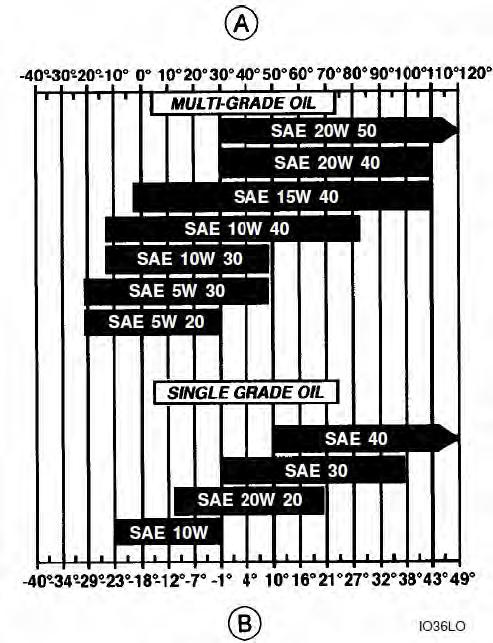
Type of fuel “FLUIDS AND LUBRICANTS”
12.1 Replacingthe Primary Filter
• Do not fill the new filter with fuel before installing it.
• Over tightening of bolt can damage the seal and the filter.
Tool required
•One 17 mm (21/32 inch) wrench for hexagonal head bolts
Procedure
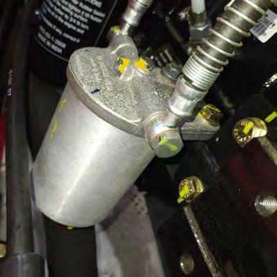
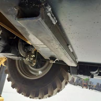
1. The primary fuel filter can be accessed by raising machine from loader end.

2. Place a receptacle of a suitable capacity under the filter (1), unscrew the screw (2) located under the filter and allow the fuel to flow out. Then re tighten screw.
3. Unscrew the bowl from the head, remove the filter cartridge and thoroughly clean the bowl.
4. Apply a fine layer of oil or grease on the new filter seal.
5. Install the new filter cartridge , and tighten the bowl
6. Vent the fuel system. See “Bleeding the system”.
7. Remove the support strut and lower the loader attachment.
12.2 Replacing the Secondary Filter (Water Separator)
1. To access the engine see " Engine Access".
2. Remove the cartridge (1) by rotating in anticlockwise direction using a filter spanner.
3. Collect dripping fuel in a tray.
4. Discard the removed cartridge .
5. Clean the sealing surface of the filter head (2).
6. Apply a light film of oil to the rubber gasket of the new filter cartridge.
7. Screw in the new cartridge finger tight against the gasket.
8. Tighten the fuel filter cartridge with a final half turn using filter spanner.
9. Vent the fuel system. See "Bleeding the system".
10.Remove the safety strut and lower the loader attachment.
12.3 BleedingtheSystem
•If the drive cam of the fuel lift pump is at the point of maximum lift, it will not be possible to operate the priming lever. In this case, turn the engine crankshaft one revolution.
•Never operate the starter motor for more than 30 seconds at a time. Wait 2 minutes before recommencing.
Tool required
•One 11 mm (7/16 inch) wrench for hexagonal head bolts. It is necessary to bleed the fuel system when:
•The tank has been completely emptied.
•Parts of the fuel system have been removed for servicing or repair work.
•The machine has been in storage for a fairly long period.
Procedure
1. To access the engine see “Engine Access”.
2. Loosen the vent screw (1) on the primary Fuel filter.
3. Operate the hand primer (2) until fuel flows without air bubbles.
4. Tighten the vent screw on primary fuel filter while the diesel fuel is flowing without air bubbles.
5. Similarly bleed the secondary filter by loosening the vent screw on it and tighten it after removing the air lock.
6. Close and lock the engine bonnet.
7. Remove the support strut and lower the loader attachment.
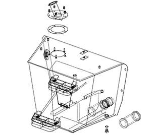
12.4 Fuel Tank Sediment Removal
Tool Required
•One 27 mm (13/32 inch) wrench for hexagonal head bolts. Place a receptacle of a suitable capacity under the fuel tank, unscrew the drain plug (1) ,located at the bottom of the fuel tank , by one or two turns and allow the soiled fuel to flow out. Then re-tighten the plug.
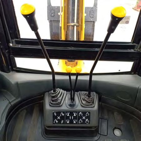
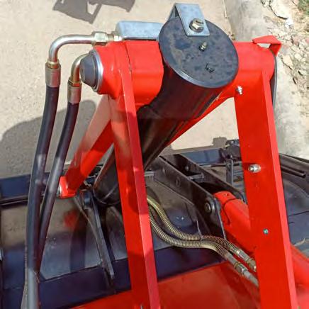
13. RELEASING THE PRESSURE IN THE HYDRAULIC SYSTEM
Note
•Before carrying out any service operation on the hydraulic system, it is first necessary to release the pressure in all the circuits.
Procedure
1.Lower the loader attachment and the backhoe attachment until they are resting on the ground.
2.Stop the engine, engage parkingbrake. Remove the starter switch key go to procedure 3 then 4.
3.Operate the loader attachment controls and 7 in 1 loader bucket (if equipped) in all directions.
4. Operate the backhoe attachment controls in all directions to release the pressure.

14. HYDRAULIC SYSTEM
Service specifications
Hydraulic reservoir or level check
Hydraulic fluid return filter replacement
Draining the circuit
Cleaning the intake strainer
Every 10 hours every week
Every 500 hours or when the warning light on the instrument panel comes on
Every 1500 hours
Every 1500 hours
Reservoir capacity 90 liters
Type of fluid “FLUIDS AND LUBRICAN TS”.
14.1 Reservoir level PROCEDURE
1.Park the machine on flat, level ground.
2.Lower the loader bucket flat on the ground.
3.Make sure that the backhoe attachment is in the road travel position.
4.Stop the engine, engage parking brake, remove the starter switch key and wait until the fluid reaches ambient temperature.
5.The fluid level should be in the middle of the sight gauge. Top up if necessary.
14.2 Replacing the Hydraulic Fluid Return Filter
•Viewed from underside of machine.
Note
•Viewed from underside of machine install the new fil-ter. Turn the filter until the seal is in contact with the filter head and tighten the filter a further half turn by hand.


• Do not use the filter wrench to tighten. Over tighten-ing can damage the seal and the filter.
•After using the machine, check that there are no leaks.
Tools Required
•One filter wrench
•One oil can
PROCEDURE
1.Lower the loader bucket flat on the ground, engage parking brake, stop the engine and remove the starter switch key.
2.Clean around the filter head.
3.Place a receptacle of a suitable capacity under the filter, loosen the filter by means of the filter wrench
4.and then unscrew it by hand.
5.Apply a thin layer of oil on the new filter seal.
14.3 Cleaningthe Strainer
Tool Required
•One 13 mm (1/2 inch) wrench for hexagonal head bolts.
Procedure
1.Lower the loader bucket flat on the ground, engage parking brake, stop the engine and move the starter switch key.
2.Clean around the filler tube.
3.Remove the bolts (1) securing the filler tube (2) and remove it.
4. Remove strainer from intake pipe by hand, clean and dry it.
5.Refit and tighten by hand, careful to avoid straining the pleats.
6. Renew the gasket (4). Apply Loctite to both sides of gasket before fitting. Fit filler tube .
14.4 Replacing the Hydraulic Fluid
Replacing the hydraulic fluid requires the fluid to be systematically drained from the main components (reservoir, pumps, cylinders, control valves, hydraulic motors and oil cooler). We recommend you to consult your local dealer.
14.5 DRAINING
Note
When carrying out draining, the hydraulic fluid must be at operating temperature.
See “Replacing the hydraulic fluid return filter” if the filter has to be replaced.
Tool Required
•One 27 mm (13/32 inch) wrench for hexagonal head bolts.
PROCEDURE
1.Park the machine on flat, level ground.
2.Lower the loader bucket flat on the ground.
3.
4.
Make sure that the backhoe attachment is in the road travel position. Engage parking brake, stop the engine and remove the starter switch key. Place a receptacle of about 100 liters capacity under the reservoir and remove the filler cap (1)and the drain plug (2). Allow the fluid to flow out.
5.Drain the other components by removing the supply and return unions. Consult your local dealer.
6.Install the reservoir drain plug (2).
Filling
7. Clean around the filler cap and fill the reservoir with the correct hydraulic fluid.
8. The fluid level should be in the middle of the sight gauge (3).
9.Install the filler cap
10.Start the engine and operate the loader attachment and backhoe attachment functions for 3 to 4 minutes.
11.Once again place the loader bucket flat on the ground and the backhoe attachment in the road travel position. Stop the engine, engage parking brake and remove the starter switch key.
12.Check the level. The fluid level should come up to the middle of the sight gauge. Top up if necessary.
14.6 Hydraulic Pump
If the flow of hydraulic fluid at the pump has been interrupted when hydraulic fluid has been replaced or when the pump has been replaced or if a pipe has burst, it is necessary to service the hydraulic pump. Consult your local dealer.

15.AIR FILTER
15.1 Inspection
•Be sure to carry out regular checks on the air filter, intake manifold, gaskets and seals. At the same time, check the intake manifold screws and hose clamps for tightness.
•The hoses should be replaced before they are worn.
•Check frequently that the air filter restriction warning lamp on the instrument panel is in good working order.
15.2 Air Filter Restriction Warning Indicator
•Carefully observe the air filter service intervals. The life of the engine depends on the cleanliness of the air filter. Service specifications
Primary element maintenance ......... Clean or replace when the restriction indicator indicates.
Primary element replacement ........... After 2 cleanings
Secondary element replacement ....... To be replaced along with the primary element.
15.3 Air Filter Elements
• Your machine is fitted with a two stage air filtering system, consisting of a high capacity primary element, designed to provide optimal protection of the engine, plus a secondary element which provides extra engine protection. •The large outer primary element can be cleaned. The smaller inner secondary element can not be cleaned and should be replaced.
15.4 Removing the Elements
The secondary element must not be cleaned. It must be replaced every year or after three cleaning of the primary element.
PROCEDURE
1. To access the engine see “Engine Access”
2. Undo the filter housing cover clips(1) holding and remove the cover.
3. Carefully remove the primary element (2).


4. If the secondary element (3) has to be replaced, take care while removing.

15.5 CleaningthePrimaryElement
WARNING
When using compressed air, take the necessary pre-cautions to protect your face. Compressed air pressure should not exceed 7 bar (101lbf/in 2). Do not use com-pressed air if there is oil or soot in the element.
Tool required
•A compressed air line
• If the primary element is dry: Blow compressed air from the inside towards the outside at very low pressure. The compressed air nozzle should be held at least three centimeters from the inside wall of the primary element. Cleaning is completed once no more dust comes out of the primary element.
15.6 InspectingthePrimaryElement
Replace the element if light can be seen through a hole, however small.
Tool required
•An inspection lamp Check the primary element for damage by placing an inspection lamp inside.
15.7 Installing the Elements PROCEDURE
1. Clean the inside of the filter body by means of a clean cloth.
2. Carefully install a secondary element if the old element had to be replaced.
3. Carefully install the primary element (1).
4. Install the cover and fasten the clips (2).
5. Close and lock the engine bonnet.
6. Remove the support strut and lower the loader attachment.
Note
On synchroshuttle the transmission oil level must be checked with the engine switched off

Service specifications
•Oil level check
• Filter replacement
• Cleaning the screen filter
• Oil change
•Total system capacity
•Type of oil
Every 10 hours (After the first 10 hours during the running-in period). Every 500 hours (After the first 500 hours during the running-in period). Every 500 hours (After the first 500 hours during the running-in period). Every 1000 hours(After the first 500hours during the running-in period) 15 liters.
See “FLUIDS AND LUBRICAN TS”.
•Check transmission mounting bolt torques Every 250 hours (After the first 50 hours during the running-in period).

16.1 Oil Level
Procedure
1. To access the engine see “Engine Access”
2. With the engine switched off, remove the dipstick (1), clean it with a clean cloth and replace it in the guide tube up to the stop. Then remove it again.

3. If the oil level is below the mark (2) , top up oil .
4. Close and lock the engine bonnet.
5. Remove the support strut and lower the loader attachment.
16.2 Draining
Tool required
Procedure
1. To access the engine see “Engine Access”.
2.Place a receptacle of a capacity of about 15 liters for synchroshuttle transmissions under the drain plug and remove the drain plug.
3.Remove the filler cap and allow the oil to flow out.
4.Install the drain plug (1) and the filler cap (2).
Service specifications
Oil level check
Oil change
Cleaning the breathers (rear)
Front drive axle oil capacity
Front reduction gear oil capacity (each)
Rear drive axle oil capacity
Rear reduction gear oil capacity (each)

17.1 Frontdriveaxleoillevel
Tool required
Every 250 hours (After the first 50 hours during the running in period)
Every 1500 hours (After the first 500 hours during the running in period)
Every 250 hours
8 liters
1.0 litres 14.5 liters 1.5 liters
•One 17 mm (21/32 inch) wrench for hexagonal head bolts.
PROCEDURE
1. Park the machine on flat, level ground, stop the engine, engage parking brake and remove the starter switch key.
2.Uninstall the plug
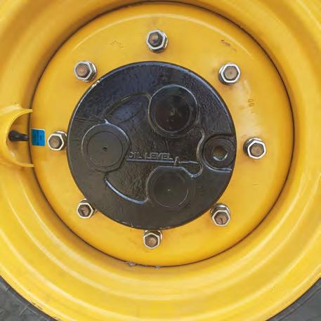
3.Check the oil level , it should be at the edge of plug hole.

17.2
FrontAxleReductionGearOilLevel
Tool required
•One 17 mm (21/32 inch) wrench for hexagonal head bolts.
PROCEDURE
1.Park the machine on flat, level ground.
2.Make sure that the direction of travel control lever and gear change lever are in neutral position.
3.Use the loader attachment to raise the front of the machine slightly so that the front wheels are no longer in contact with the ground and place blocks under the front drive axle. Chock rear wheels.
4.Stop the engine, engage parking brake and remove the starter switch key.
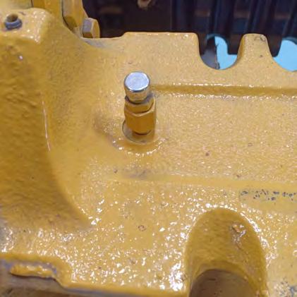
5. Manually turn the wheel until the orifice is in the horizontal position and remove the plug.
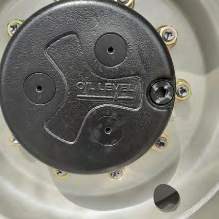
6.The oil should be level with the orifice If necessary, top up via this orifice.
7.Install the plug.
8.Repeat Steps 5 to 7 for the other reduction gear.
9.Lower the machine to the ground.
Cleaning the Breather
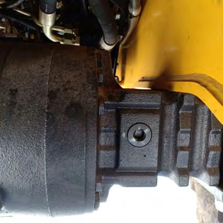
17.3 Rear drive axle oil level

Tool required
•One 12.5 mm (1/2 inch) wrench for square recessed plugs.
Procedure
1.Park the machine on flat, level ground, stop the engine, engage parking brake and remove the starter switch key.
2.Remove the plug and check that the oil is level with the plug hole(1). If necessary, top up via this hole (1).
3.Install the plug.
17.4 RearAxleReductionGearOilLevel
Tool required
•One 17 mm (21/32 inch) wrench for hexagonal head bolts.
Procedure
1.Park the machine on flat, level ground.
2.Make sure that the direction of travel control lever and gear change lever are in neutral position.
3.Use the stabilizers to raise the rear of the machine slightly so that the rear wheels are no longer in contact with the ground and place blocks under the rear axle. Chock front wheels.
4.Stop the engine, engage parking brake and remove the starter switch key.
5.Manually turn the wheel until the orifice is in the horizontal position and remove the plug.
6.If necessary, top up via this orifice.
7.Install the plug.
8.Repeat Steps 5 to 7 for the other reduction gear.
9.Lower the machine to the ground.
Cleaning the Breather
Check that the rear axle breather is not blocked or damaged.
17.5 Draining and Filling the Front Drive Axle
Tools required
•One 11 mm (7/16 inch) wrench for hexagonal socket head bolts.
•One 17 mm (21/32 inch) wrench for hexagonal head bolts.
Procedure
1. Park the machine on flat, level ground, stop the engine, engage parking brake and remove the starter switch key.
2.Remove the drain plug (2) and let the oil flow out to a suitable container .
3.Install the drain plug (2).
4.Fill with oil via the filler orifice (1) until the oil is level with the orifice. Then install the plug.
17.6 Draining and Refilling the Front Axle Reduction Gears
Tool required
•One 17 mm (21/32 inch) wrench for hexagonal head bolts.
Procedure
1.Park the machine on flat, level ground.
2.Make sure that the direction of travel control lever and gear change lever are in neutral position.
3.Use the loader attachment to raise the front of the machine slightly so that the front wheels are no longer in contact with the ground and place blocks under the front drive axle. Chock rear wheels.
4.Stop the engine, engage parking brake and remove the starter switch key.
5.Turn the wheel by hand until the orifice is in the lowest position.
6.Place a receptacle of about 2 liters capacity under the reduction gear, remove the plug and allow the oil to flow out.
7. Turn the wheel by hand until the orifice is in the horizontal position and then fill via that orifice until the oil is level with the orifice.

8.Install the plug.
9.Repeat Steps 5 to 8 for the other reduction gear.
10.Start engine and lower the machine to the ground.
17.7 Draining and Filling the Rear Axle
Tool required
• One 12.5 mm (1/2 inch) wrench for square recessed plugs.
Procedure
1.Park the machine on flat, level ground, stop the engine, engage parking brake and remove the starter switch key.
2.Place a receptacle of about 14.5 liters capacity under the drain plug (1), remove the drain plug(1) and allow the oil to flow out.
3.Install the drain plug.

4.Fill with oil through the filler orifice (2) until the oil is level with the orifice. Then install the plug.
17.8 Draining and Refilling the Rear Reduction Gears
Tool required
•One 17 mm (21/32 inch) wrench for hexagonal head bolts
Procedure
1.Park the machine on flat, level ground.
2.Make sure that the direction of travel control lever and gear change lever are in neutral position.
3.Use the stabilizers to raise the rear of the machine slightly so that the rear wheels are no longer in contact with the ground and place blocks under the rear axle. Chock front wheels.

4.Stop the engine, engage parking brake and remove the starter switch key.
5.Turn the wheel by hand until the orifice is in the lowest position.
6.Place a receptacle of about 2 liters capacity under the reduction gear, remove the drain plug and allow the oil to flow out.
7.Turn the wheel by hand until the orifice is in the horizontal position and then fill via that orifice until the oil is level with the orifice.
8.Install the plug.
9.Repeat Steps 5 to 8 for the other reduction gear.
10.Start engine and lower the machine to the ground.
Note
Only use Manitou recommended Brake Oil. Do not overfill, as spillage from the breather may occur when working on steep gradients. Any sudden loss of fluid must be reported immediately to your local dealer.
Service specification
Brake fluid level check Brake fluid change 18.1

Level
Procedure
Every 50 hours Every 1500 hours
1.Park the machine on flat, level ground.
2. To access the engine see “Engine Access”. The level in the brake fluid reservoir should be between marks Max. and Min. level.
3.Ensure breather hole in cap is not blocked.
4.Close and lock the engine bonnet.
5.Remove the support strut and lower the loader attachment.
18.2 DrainingtheBrakeFluid
Loosen both the bleed screws on the brake housings of the rear axle. Exhaust all fluid from system by pumping both the brake pedals. Top up reservoir as required. Keep pumping both brake pedals until clean fluid emerges. Finally vent air from brake system.