8 minute read
2. LOADER ATTACHMENT OPERATING INSTRUCTIONS

Note
Automatic loader bucket levelling only operates when raising the attachment; it does not operate when lower-ing the attachment. You must take care to keep the buck-et level during attachment lowering to avoid the load be-ing dumped.
Operating the loader attachment with a full bucket on sloping ground can cause the machine to turn over. If possible avoid turning the steering wheel and always travel forwards when climbing a slope and in reverse when travelling down a slope. Keep the bucket as close as possible to the ground. There is a risk of accident if these instructions are not observed.
On the job site,always keep the bucket as close as possi-ble to the ground so as to increase the machine’s stability to the maximum ad to ensure perfect visibility.
On rough or slippery ground, when the bucket is full, drive the machine as slowly as possible. If these instruc-tions are not observed there is a risk of accident.
The machine will free wheel when the button is pressed. If necessary, use the brakes to stop the machine. Raise the attachment so that the bucket is about 20 cm (8 inch)above the ground Ensure lifting or handling weight does not exceed 1000 kg (2204 lbs).
NOTE:
• The first time it is operated, manoeuvre the machine in a clear area, at low speed.
• The instructions contained in this chapter do not cover all possible conditions of use of the loader attachment. They only constitute basic information to enable the machine to be operated correctly.
Safety Instructions:
1. Be careful.
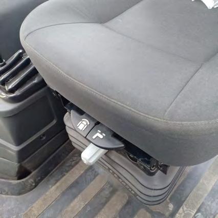
2. Make sure that the operator’s seat is correctly adjusted in the loader attachment position.
3. Use the seat belt.
4. Make sure that no other person is in the working range of the machine.
2.1 Standard Bucket Level Indicator
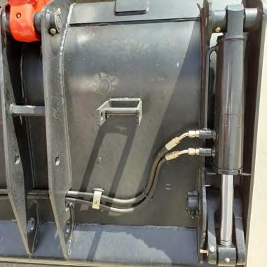
Located on the bucket cylinder, this indicator enables the loader bucket to be positioned flat when the pointer is opposite the red pointer.
2.2 7 In 1 Loader Bucket (If Equipped
Load lifting configuration
7 in 1 loader bucket clam opening indicator (if equipped) Located on the cylinders of the clam, this indicator enables the clam opening and depth of penetration of the bucket to be selected when the bucket is in the scraper configuration.
2.3 Organising The Job Site
• Use the shortest possible work cycle.
•The location provided for the trucks is an all important element. Spend a little time levelling the work area.
•A smooth working surface facilitates the work of the machine and moving and parking the trucks. It gives a shorter work cycle.
2.4 Heaped Material
• Using the indicator, check that the bottom of the bucket is in the horizontal position.
• Drive the machine into the heap of material.
• When the speed of the machine starts to decrease, raise the attachment and crowd the bucket backwards.
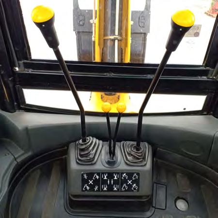
3. BACKHOE ATTACHMENT OPERATING INSTRUCTION
Note
The first time Backhoe Attachment is operated, manoeu-vre the machine in a clear area, at low speed.
The instructions contained in this chapter do not cover all possible conditions of operation for the backhoe attachment. They only constitute basic information to enable the machine to be operated correctly.

3.1 Safety Instructions
1.Use the seat belt.
2. Make sure that the operator’s seat is correctly adjusted in the backhoe attachment position.
3.Never operate the machine in slushy ground or never operate the machine in submerged condition.
4. Make sure that no other person is in the working range of the machine and be aware of people entering the working range of the machine during operation.
5. Place the attachment in the working position. See“SETTING THE MACHINE IN THE BACKHOE ATTACHMENT WORKING POSITION”.
6. Never dig near or under the stabilizers, since the machine could fall into the excavation.
7. When working in an area of reduced visibility, for example next to a building, place a safety barrier and sign panels to prevent anyone coming near the machine.
3.2 General
The backhoe attachment will dig more quickly if the work cycle is short and uninterrupted. Organize your work site so as to obtain a smooth work cycle.
If you try to take a very big cut with the backhoe bucket, you may cause a hydraulic stall situation (where the dipper control lever is pulled towards the operator but nothing happens).
The hydraulic system main relief valve makes a noise when a hydraulic stall occurs. This overload causes the work cycle to be prolonged and it increases the hydraulic temperature.
3.3 Moving the Machine Forwards When Working on Flat Ground
Note
This procedure can only be used on flat ground. Never use it on sloping ground. On sloping ground it is essential to turn the operator’s seat to the loader attachment position to move the machine by the normal procedure. It is possible to use the backhoe attachment to push the machine forward whilst excavating.
Procedure
1. Make sure that no other person or obstacles are in the working range of the machine.
2. Make sure that the front wheels are straight.
3. Set the engine speed to 1000 rpm.
4. Release the machine’s brakes by means of the parking brake.
5. Make sure that the direction of travel and gear change levers are both in the neutral position.
6. Raise the boom and retract the dipper, then move the boom so as to place the backhoe bucket teeth on stable ground.
7. Raise the stabilizers and the loader bucket about 20 cm (8 inch) from the ground.
8. Use the boom and dipper to move the machine.
9. After moving the machine, lower the stabilizers and place the loader bucket on the ground, then level the machine.
10. Use the parking brake to brake the machine.
Wrong
The backhoe bucket will dig in and cause a stall.
Correct Excavating Method
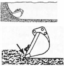

3.4 Filling the Backhoe Bucket
Fill the backhoe bucket by manoeuvring the boom and dipper. Keep the bottom of the backhoe bucket parallel to the cut. The backhoe bucket teeth and blade must cut the ground like the blade of a knife. The depth of dig varies depending on the type of material.
Wrong
The bucket is pushed upwards. This will also increase the cycle time.
4. EXTENDED DIPPER (If Equipped)
NOTE
The bucket must not be resting on the ground - dipper must be supported.
Service specification
Replacement of the internal and external wear pads
4.1 Top and bottom wear pads
Tool required
• One 19 mm (3/4 inch) wrench for hexagonal head bolts.
• One 17 mm (11/16 inch) wrench for hexagonal head bolts.
Procedure
As required.
1. Position the extendable dipper so that the inner member is extended approximately 30 cm (12 inch) and is resting on the bottom wear pad.
2. Remove all six bolts (1) and lift off top plate (2). Then remove both bolts (1a) and retainer plate (2a).
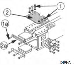
3. Slide out the old wear pad (3) and replace it with a new one.
4. Refit the plate (2), washers (4) and bolts (1), which should be tightened to 140 Nm (104 lbf ft). Refit retainer plate (2a)and bolts (1a) and tighten to 140 N m (105 lbf ft).
5. Lower the extendable dipper until the bucket contacts the ground so that the inner extendable member is pressed against the top wear pad.

6. Remove three bolts (5) and the retainer plate (6).


7. Remove the bottom wear pad (7) and shims (7a).
8. Fit a new wear pad and adjust the shim thickness to give a maximum gap of less than 1 mm.
9. Refit the retainer plate (6) and tighten bolts (5) to 140 N m (105 lbf ft). Side wear pads
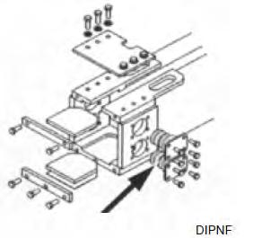
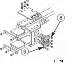
4.2 Side wear pads
10. Raise dipper, bucket must be clear of the ground (dipper must be supported).
11. Remove sixteen bolts (8) and all four housings (9), shims and wear pads.
12. Place a 1 mm shim, a 2 mm shim and a new wear pad into two of the housings.
13. Fit both housings to one side of the extendable dipper outer member. Fit the bolts and tighten to 60 N m (45 lbf ft).

14. Push the inner member hard against the wear pads just fitted.
15. Fit two new wear pads into the remaining housings and assemble the housings to the opposite side of the outer member. Fit and partially tighten all eight bolts.
16. Measure the clearance between the inner member and the wears pads just fitted.
17. Remove the housings fitted in step 15 and add shims behind the wear pads to achieve a total clearance between the wear pads and the inner member of less than 1 mm.
18. Fit and tighten the bolts to 60 N m (45 lbf ft).
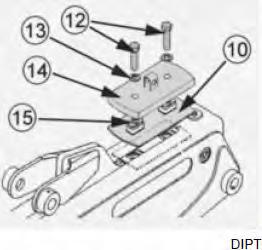
4.3 Checking and Adjustment of Tail Upper Wear Pads PROCEDURE
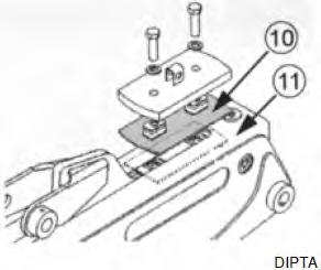
1. Position the backhoe to full reach, the dipper extended 3/4 travel and the bucket maintained 50 mm (2.0 ins) above the ground.
2. The wear clearance between the outer wear pad (10) and the dipper (11) should be maximum 1.0 mm (0.04 in).
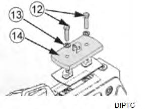
3. If adjustment is required, remove both bolts (12), washers (13), and retainer plate (14). Remove sufficient shims (15) equally at both locations to compensate for the measured wear clearance at step 2.
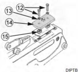
4. Refit the retainer plate (14), washers (13) and both bolts (12) which must be torqued to 920 N m (690 lbf ft). Recheck wear clearance refer to step 2 and make further adjustments if required.
4.4 Replacement of Tail Upper Wear Pads and Internal Wear Pads
• A smear of heavy grease will help retain the shims and wear pads during assembly.
• Adjustment of these wear pads must be carried out when dipper is fully assembled. Continue to next step.
• Adjustment of the Tail Upper wear pads must now be checked.
Procedure
1. Remove the bucket, bucket link (17) and bucket cylinder (18) from the dipper (11).
2. Remove the top, bottom and side wear pads (19) from the end of the dipper.
3. Extend inner section (23) fully, remove circlips from the extension cylinder mounting pin (20), then drive out the pin.
4. Remove both bolts (12) washers (13) and retainer plate (14). Remove shims (15) and outer top wear pad (10). Leave spacers in place.

5. Support the inner section (23) by means of a suitable chain sling and bars inserted through the bucket cylinder mounting hole (21) and bucket pivot pin hole (22). Slide the inner section (23) out of the dipper (11).


6. Remove both side wear pads (24), shims (25) and top inner wear pad (26) from the inner section (23).
7. Fit new wear pads (24) (without shims) into each side of the inner section. Measure the total width between the outer wear pads faces, this is: Dimension A (mm). Measure the internal width of dipper outer section, this is: Dimension B (mm).
•Thickness of shims required = Dim. B - Dim. A - 0.5 to 1.0 mm
• Divide shims equally (up to 1.0 mm difference allowed) and install under the side wear pads.
9. Fit a new outer top wear pad (10), spacers, shims (15) (3 mm thickness shims fitted above spacers), retainer plate (14),washers (13) and bolts (12).
10. Align and fit mounting pin (20) through inner section (23)and extension cylinder then secure with circlips.
11. Refit the top, bottom and side wear pads (19) to the end of the dipper. Refit the bucket, bucket link (17) and bucket cylinder (18) to the dipper (11).