7 minute read
19.ENGINE ACCESS

Note
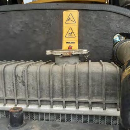
Many of the checks and operations referred too in this section require access to the engine. Take the following steps to safely gain access to the engine.
Procedure
1. Park the machine on flat, level ground.
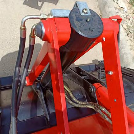
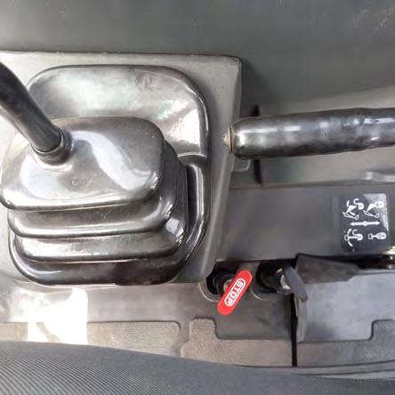
2. Raise the loader attachment, stop the engine, engage parking brake, remove the starter switch key and install the safety strut (1).
3. Unlock the engine bonnet by pulling up the lever (2).
20. WHEELS AND TYRES
Warning
•A burst tyre can cause serious injury.
•Regularly check the condition of tyres and always observe the inflation pressures defined in accordance with the type of tyre and ground concerned.
•When checking tyre pressures or during an inflation operation, never face the tyre.
•Always use an inflation cage when the wheel is re-moved from the machine. Keep all other persons away from the area.
•Never weld near a tyre. It is essential to remove the tyre before any welding operation.
20.1 TyrePressures
Note
Make sure you protect your face before using com-pressed air.
Note: Inflate the tyres to the recommended tyre pressure.
Service specification
20.2 Wheel Nut Torque Settings
Tool required - A torque wrench
Service specifications
• Torque tightening check
•Front wheel nuts
•Rear wheel nuts
20.3 Replacing a Wheel
Every 250 hours (Every day for five days, after removing a wheel)(After the first 50 hours during the running-in period)
300 N m
600 N m
• Make sure that the new wheel has a sufficient inflation pressure. Reinflate it if necessary.
Note
Make sure you protect your face before using compressed air.
Tools required - One 24 mm (15/16 inch) or 27 mm (11/16 inch) or 33 mm (11/4 inch) wrench for hexagonal head bolts.
Procedure
1.Park the machine on flat, level ground, with no obstacles in the area.
2.Loosen the retaining nuts from the wheel which is to be removed.
3.Start the engine and use the loader attachment and the stabilizers to lift the machine until the wheels are no longer in contact with the ground.
4.Stop the engine, engage parking brake and remove the starter switch key.
5.Place blocks under the axle for the wheel which is to be removed.
6.Remove the nuts and remove the wheel.
7.Install a new wheel, observing the orientation of the tread pattern.
8.Install the nuts and tighten them to correct torque, see “Wheel nut torque settings”.

9.Remove the blocks from under the axle.
10.Lower the machine to the ground.
Tyre or Wheel Service
The servicing of tyres and wheels for this machine should only be entrusted to a qualified mechanic, who will know how to inflate the tyres while observing safety instructions.
To avoid any accident, use a protective device (an inflation cage for tyres), suitable tools and respect the procedure. Serious or fatal injury can result from a tyre suddenly flying off a rim (one piece rim) or from the tyre and/or the wheel components (a wheel consisting of several parts).
21. RADIATOR & OIL COOLER

The use of trichlorethylene is strictly forbidden.
Service specifications
• Checking for leaks Every 10 hours or every day.
• Cleaning As required.
Procedure
1. To access the engine see “Engine Access”.
2.Clean:
•Dry dust: Use compressed air.
•Mud: Use a water jet.
•Oily dust: Use perchlorethylene
3.Close and lock the engine bonnet.
4.Remove the support strut and lower the loader attachment.
22. FAN BELT
Service specification
• Check Every 250 hours (After the first 50 hours during the running-in period).
22.1 Inspection PROCEDURE
1. To access the engine see “Engine Access”.
2. Press the fan belt midway between the pulleys by hand. The deflection should be more than 10 - 15 mm (0.39 - 0.59 inch).
3.Inspect the V-belt over whole length for damage or cracks .
4.Renew damaged or cracked V-belt .
22.2 Replacement
Tool required - One 13 mm (1/2 inch) wrench for hexagonal head bolts.
Procedure
1. To access the engine see “Engine Access”
2. Slacken the bolt (1) and push the alternator. Remove the fan belt.
3. Install a new fan belt.
22.3 EngineValveTipClearanceAdjustment
Service specification
Inspection Every 1000 hours (After the first 50 hours during the running-in period).
To be done by engine dealer only.
Tappet clearance ( in cold condition only )
Inlet - 0.30 mm
Exhaust - 0.30 mm
Service specifications- Inspection and cleaning - Every 1000 hours Or whenever oil or grease has been spilled on the machine; clean such deposits off with steam or high pressure water.
Take advantage of this operation to make a visual check of all the welded components (possible appearance of cracks), and the attachment linkage. Mark any leaks, check the condition of pipes and hoses.
23. MACHINE INSPECTION AND CLEANING 24. CYLINDER LEAK INSPECTION
A cylinder rod should be slightly oily. Check for leaks after a working period, when the entire hydraulic system is at normal operating temperature.
1. Clean the rod and the gland of the cylinder which is to be inspected.
2. Work normally for 5 to 10 minutes.
3. Extend the cylinder rod.
4. Check for leaks.
Rod Appearance Test Conclusion
Dry
Slightly oily
Oily
Slight traces of oil when a sheet of paper is rubbed over 20 cm of the rod. Normal
The paper remains stuck when run over the rod. Normal

A sheet of paper placed on the rod stays stuck to it. Normal
Very oily or weeping A ring of oil is visible on the rod after each rod extension. Consult your local dealer Leak. Oil drips from the gland every time the cylinder rod is retracted
25. PARKING BRAKE INSPECTION
Service specification
Check Every 50 hours. Check and adjustment Every 2000 hours.
25.1 Parking Brake Check PROCEDURE
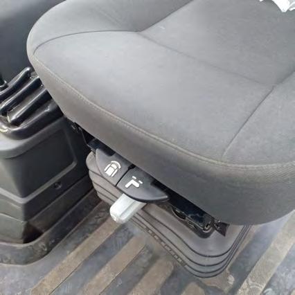
1. Engage the parking brake (1)and start the engine.
2. Place the gear change lever in third gear, then place the direction of travel control lever in forward drive. The audible warning device will sound.
3. Using the accelerator pedal (2), increase the engine speed to about 1600 rpm. The machine must not move. If the machine moves, adjust the brake. See “Parking Brake Adjustment”.

25.2 Parking Brake Adjustment
Note
Make perfectly sure that the jacks are capable of supporting the weight [8700 lb. (3944 kg.)]
Make sure inner adjuster nut (2) does not turn relative to bolt (3). Start the engine and raise the loader 30 cm above the ground. Use the stabilizers to raise the rear of the machine. Park the machine on flat, level ground, with the loader beams 30 cm above the ground. Make sure that the backhoe boom locking device is engaged.
1.Use the stabilizers to raise the rear wheels.
2.Use workshop jacks to support the rear of the machine, making sure the wheels are not touching the ground.
3.Lower the loader arms to the ground, stop the engine,remove the starter switch key and release the parking brake.

4.Adjust the length of parking brake cable by adjusting the locking nuts .
26. SERVICE BRAKE CHECK AND ADJUSTMENT
Note
The area where brake testing is carried out ,must be clear from any obstacle , animals or human being. Only skilled operator should carry out brake testing.
1.Enter the machine. Fasten the seat belt properly and park the machine on a level ground.
2.Lock the brake pedals together.
3.Start the engine and raise the attachments in traveling position.
4.Run the engine at 1500 or more RPM.
5.Run the machine in 2nd , 3rd or 4th gear and apply the brakes.
6.If machine stops to a complete halt , brake is good .
7.If machine does not stop completely , brake is poor.
Brake Adjustment-
1.Master cylinder push rod clevis should be loosened or tightened to adjust the brake pedal height. Brake height should be maintained between 170 -190 mm from the cabin floor for proper brake efficiency .
2.Brake circuit must be free from any air , bleed off the air if required .
27. STEERING AND AXLES
Service specifications
•Check power steering system pipes, hoses and unions for damage or leakage in Every 250 hours
•Check All Steering System Fasteners and All Ball Joints and Pivots For Wear If wear or excessive play occurs in the steering mechanism contact your local dealer.
•Check Power Steering System Pipes, Hoses and Unions for Damage or Leakage
This machine is equipped with hydrostatic power steering and it is therefore important that hoses are maintained in perfect condition and that no leaks occur anywhere in the steering system. If accessories have been added after the machine was purchased, check to ensure that they do not interfere with steering system hoses or components.
Replacement of Cardan Fasteners
Tool required - A torque wrench
When replacing or checking the tightness of the mounting bolts for the front and rear cardan shafts it is essential that new bolts are used each time. These should be Genuine manufacturers parts which are locktite coated.
28. TRANSMISSION
Service specification
Check transmission mounting bolt torques Every 250 hours (After the first 50 hours during the running-in period)
Tool required - A torque wrench
•Check the tightness of the eight transmission mounting bolts (four each side of machine).


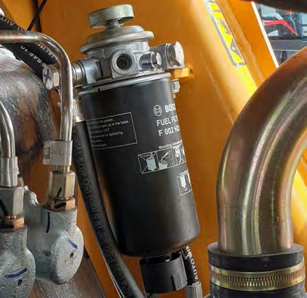
29. FUEL INJECTORS
Service specification
Fuel injection atomizers require regular servicing to maintain efficient operation. This work must be done by Authorised Dealer.
Early signs of atomizer malfunction are:
•Misfiring.
•Knocking in one or more cylinders.
•Engine overheating.
•Loss of power.
•Black smoky exhaust.
•Increased fuel consumption.
Other faults can cause apparently similar symptoms and should be checked before removing injectors.
•Water in the fuel.
•Wrong fuel.
•Dirty or damaged fuel filters.
If none of these faults are present then call your local dealer.
30. TURBOCHARGER
Service specification
(Consult Authorised Dealer)
The following items are precautionary measures only, designed to ensure the continued performance of the turbocharger. This work is best entrusted to your local dealer.
• Remove and clean the oil drain pipe between the turbo-charger and sump.
• Remove the air inlet duct and compressor housing and check for dirt/carbon deposits which must be cleaned off the compressor wheel with a soft brush. An uneven deposit will unbalance the wheel and cause premature bearing failure. If any deposits are found, the source of the contamination must be traced and corrected.
• While the compressor housing is removed, turn the compressor wheel, while pushing on the end of the shaft. Listen for unusual noises which indicate that either the compressor or turbine wheels are touching the housing. If any such noises are heard, the turbo-charger must be removed and inspected immediately, by your local dealer
31. REPLACING A BATTERY

Tool required - One 10 mm (3/8 inch) wrench for hexagonal head bolts.
NOTE
Never reverse the battery terminals. Connect the positive cable to the positive terminal (+) and the negative cable to the negative terminal (-).
Procedure
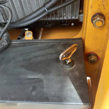
1.Disconnect the battery disconnect switch (2)(if equipped).
2.Disconnect the cables (first from the negative terminal then the positive terminal).
3.Remove the battery cover by opening the lock (1).
4. Remove the bolts(3), the clamp and remove the old battery.
5.Install the new battery.
6.Install the clamp and the bolt.
7.Clean the cables and the connecting terminals and coat them with grease.
8.Connect the cables (first to the positive terminal, then the negative terminal).
9.Re-install the battery and lock it.
10.Switch on the battery disconnect switch (If Equipped).