34 minute read
STANDARD OPERATING PROCEDURE

3.1 General Inspection Before Operating the Machine
Note
Read the Safety Section of this manual before performing the inspection. Read and ensure that you understand the instructions and warnings shown in this manual before operating the machine.
Before each days operation of the Backhoe the operator must perform the General Inspection as outlined in the Check List on the following page.
The purpose of the Operators Inspection is to keep the Backhoe in proper working condition and to detect any signs of malfunction during normal operation between scheduled maintenance intervals. Before operating the machine, observe the following instructions.
Procedure
1. Check the levels (engine oil, transmission oil, hydraulic fluid and engine coolant) and make sure that the various fluids correspond to the conditions of use.
2. Carry out the daily maintenance operations.
3. Walk round the machine, look for any leaks and inspect the hoses. Tighten or replace any items as required.
4. Before undertaking any road travel, lock the attachments, raise the stabilizers completely and install the safety systems required by regulations.
5. Before any road travel or job site work at night, check that the lighting and signalling systems are operating correctly.
6. Check the condition and pressure of the tyres.
7. Clean the steps and access handles. The presence of oil, mud or ice (winter) can cause accidents. Make sure they are always clean.
8. Clean or replace safety decals which are no longer legible.
9. Make sure that the engine bonnet is closed and latched correctly.
10. Make sure that the cab doors (cab version) are closed correctly.
11. Remove anything which might hinder visibility. Clean the windshield windows (cab version) and rear view mirrors.
12. Make sure that no objects or tools are left on the machine or in the operator’s compartment.
13. Make sure you know how to evacuate the machine (emergency exit via the right-hand side) in case access by the lefthand side is impossible.
14. Make sure that the right-hand door (cab version) is locked.
15. Make sure that nobody is under or on the machine. The operator should be the only person on the machine.
16. Make sure that nobody is within the working range of the machine.
17. Ensure operators floor is clear of loose items.
3.2 Operating the Machine PROCEDURE
When operating the machine the following instructions must be observed :
1. Start the engine taking into account weather conditions.
2. Regularly consult the hourmeter to ensure Servicing Schedules are observed.
3. If you use the machine under particularly severe conditions (dusty or corrosive atmosphere, etc.), the Servicing Schedules should be reduced.
4. Make sure that you know the location of underground services such as gas, electricity, telephone or mains water before starting work.
5. Do not work near overhead high voltage electrical cables without checking beforehand that all necessary measures have been taken to respect the minimum distances: Under 57,000 volts: 3 metres (118 inch). Over 57,000 volts: 5 metres (197 inch).
6. On job sites on the public highway, use regulation signals, taking into account the working range of the machine. Local regulations define the number, type and location of reflective strips.
7. Make sure that the operator’s seat is correctly adjusted and positioned.
8. Never operate any control or driving component unless you are seated correctly in the operator’s seat with the seat belt adjusted and attached correctly.
9. Adapt your operating style to the type and conditions of work.
10. Do not allow anyone to stand in the machine working area. Stop all movement until the person has moved away.
11. Use all the controls gradually so that the machine works smoothly.
12. Load lifting should be carried out in accordance with the instructions given in this manual and in accordance with prevailing regulations.
13. Avoid running the engine in an enclosed space. Ensure good ventilation under all circumstances.
14. Dust, smoke or fog can reduce visibility and cause an accident. Stop or slow down the machine until normal visibility is restored.
15. If there is any operating problem or damage move the machine to a place of safety, stop the engine, engage parking brake, remove the starter switch key. Find the cause or contact your local dealer and take the necessary measures to prevent the use of the machine. Place a “Do not start up” label on the instrument panel.
3.3 Running-In Period
Your machine will last longer and give better and more economical performance if you pay particular attention to the engine during the first twenty hours of operation. During this period:
• Keep a close watch on the instrument panel.
• Check the oil and engine coolant levels frequently.
• Operate the machine at normal speeds during the first eight hours. Do not run the engine too much at stalling speeds (with the wheels turning slowly or stopped and the engine at full speed).
• Maintain the engine at the normal operating temperature.
• Do not run the engine at idle speed for long periods.
During the running-in period, the following inspections and maintenance operations must be carried out in addition to the operations shown in the Maintenance Programme:
1. After The First 50 Operating Hours
1. Change engine oil and filter.
2. Change hydraulic oil filter.
3. Check air filter.
4. Change transmission oil and filter.
5. Clean transmission strainer.
6. Change front (4 wheel drive) and rear axle oils.
7. Check front reduction gear oil level (2 wheel drive).
8. Check road wheel nuts for tightness daily until stabilised :- Rear: 300 Nm (220 lbf ft), Front: 300 Nm (220 lbf ft).
9. This wheel nut checking procedure also must be applied for any wheel which is removed and replaced, for any reason.
10. Check fan belt tension.
11. Reset engine valve tip clearance.
12. Check brake adjustment.
13. Check bolt torques on cardan shafts to front and rear axles.
14. Check bolt torques on transmission mounting bolts.
15. Check loader control lever lock (if equipped). Engage the loader control lever lock and attempt to move the loader control levers.
16. Check the automatic loader bucket levelling for correct adjustment and operation.
3.4 Starting the Engine
Note
After the machine has not been operated for an extended period, see“Starting up after storage” If you have to start the engine by means of a booster battery, see“CONNECTING A BOOSTER BATTERY”

Do not run the engine at idle for too long, since this may cause the formation of deposits in the oil. Whenever conditions of use and safety allow it, run the engine at maximum speed.
• For a temperature over 5°C, hold the key in the preheat position for ten seconds.
• For a temperature of between -5°C and +5°C, hold the key in position for twenty seconds.
• For a temperature below -5°C, hold the key in position for thirty seconds.
Never hold the key in the pre-heat position for more than one minute. Do not operate the starter for more than 30 seconds at a time. Do not operate the starter when the engine is running. If this is not done the audible warning device will sound and it will be impossible to start the engine.
Procedure
1. Connect the electrical system by means of the battery dis-connect switch (if equipped).
2. Check that the seat is properly locked in the loader attachment working position.


3. Adjust the seat and attach the seat belt.
4. Check that the parking brake is engaged.
5. Check the engine throttle lever is in low idle position.
6. Check that the direction of travel lever is in the neutral position.

7. Check that the gear change lever is in the neutral position.


10. Turn the starter switch key to the preheat position and hold it there.
11. Turn the key to the starting position. Release the key as soon as the engine starts. If the engine stops, wait about one minute before starting the operation again.
12. When the engine is running check the indicators and indicator lamps to make sure that all systems are operating correctly.
13. Using the accelerator pedal, run the engine at half speed until it has reached normal operating temperature.
3.5 Stopping the Engine
Note
In cold weather, run the engine at low idle speed for three to five minutes to reduce the engine temperature before turning off completely.
If the engine is to be stopped for a long period, see “PARKING THE MACHINE”.
Procedure
1. Place the direction of travel control lever in the neutral position.
2. Place the gear change lever in the neutral position.
3. Apply parking brake securely.
4. Allow the engine to run at idle speed for about one minute.
5. Pull the stop cable knob and hold it till the engine stops.


6 Turn the starter switch key to the “OFF” position and remove the starter switch key.
3.6 OperatingtheMachineInColdWeather
Observe the following recommendations:
1. Battery - It must be fully charged.
2. Fuel -
•Refill the fuel tank after each working day to prevent the formation of condensation and the entry of water into the fuel system.
• To prevent the formation of crystals (-2°C) use a low temperature fuel or mix a protective fluid with your fuel.
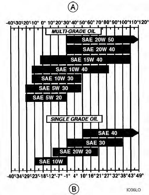
3. Engine Oil - The engine oil must have a viscosity corresponding to the ambient temperature.
4. Engine Coolant - It must have a specification corresponding to the ambient temperature. It must contain a minimum of 50% of ethylene glycol solution.
3.7 Operating the Machine in Hot Weather
Observe the following recommendations:
1. Maintain the correct level of engine coolant in the engine coolant reservoir.
2. Check the condition of the radiator cap before starting. Replace the cap if necessary.
3. Clean the radiator, the oil cooler and the engine carefully.
4. Check the condition of the alternator and fan belt.
5. Use lubricants with the recommended decree of viscosity.
6. Use an appropriate engine coolant (a mixture or ethylene glycol and water at the required concentration).
3.8 Rock Breaker (Optional)
Note
Before using rock breaker, it is necessary to proceed as follows:
•Place the direction of travel control lever in neutral position.
•Lower the loader bucket until it is pressing on the ground.
•Stop the engine, engage parking brake, release hydraulic pressure and remove the starter switch key.
PROCEDURE
- Connect the tool hoses to (1) and (2) couplers located on the backhoe dipper.


The operator must decide how much flow should be used by consulting the manufacturer’s operating instructions. Be sure to select the flow recommended. Excess flow can damage some equipment.
Flow rate setting depends on the engine speed.
3.9 Load Lifting
Note
If the machine is not equipped with the Object Handling Kit, then it must not be used for object handling. If this instruction is not observed an accident may occur. Object handling must be carried out in accordance with the instructions shown in this manual and in accordance with current regulations. A pressure setting check must be carried out on safety valves every six months in accordance with the manufacturer’s instructions. Consult your local dealer.
• For load lifting, it is essential that the machine is equipped with a load fixing point.
• For lifting operations above 1000 kg,it is a legal requirement for the fitment of hose burst lockout valves on specific services.
• To lift a load, the following instructions must be followed:
Procedure
1. Place the machine on flat, hard, level ground.
2. Lower the loader attachment until the front wheels just touch the ground without supporting the weight of the machine.
3. Lower the stabilizers until the rear wheels just touch the ground without supporting the weight of the machine.
4. It is mandatory for the backhoe attachment to be in line with the machine and the sideshift carriage to be locked hydraulically (sideshift (offset) backhoe version).
5. If the machine is equipped with an extendable dipper, it is mandatory for it to be completely retracted and mechanically locked.
6. It is essential for the backhoe bucket cylinder rod to be completely extended.
7. Use the load fixing point (never use other load fixing points). It is forbidden to weld hooks or lugs to the bottom of buckets.
8. Use slings and chains in perfect condition, able to support the load to be lifted and with an effective device preventing the slings or chains becoming unhooked.
9. Check that the safety valves operate correctly. A pressure setting check must be carried out every six months in accordance with the manufacturer’s instructions. Consult your local dealer.
10. Do not allow any person within the machine’s working range.
11. Use the controls gradually so as to move the attachment accurately.
3.10 Maximum Working Loads
Note
Before lifting a load refer to the instructions on below. The Safe Working Load of the backhoe is calculated using a standard bucket, therefore, when using any other bucket or attachment for“lifting”or“craning”the weight of the bucket or attachment must be taken into account when calculating the rated load of the backhoe. The Safe Working Load of the loader is calculated using a standard bucket, therefore, when using any other bucket or attachment for “lifting” or “craning” the weight of the bucket or attachment must be taken into account when calculating the rated load of the loader.
1. Backhoe Attachment
Safe Working Load = 1000 kg (2204 lbs)
2. Loader Attachment
Safe Working Load = 1000 kg (2204 lbs).
3.11 Operating the Machine in Water
Note
•Never work in water if the water level is higher than the centre of the front wheels.
•Never work in fast flowing water.
1. Make sure that the bed of the stream or stretch of water can support the weight of the machine.
2. The level of the water must not exceed the height of the centre of the front wheels.
3. Before taking the machine into the water, pump plenty of new grease into the machine’s attachment linkages.
3.12 Parking the Machine
Note
Check that no part of the machine is protruding onto the public highway. If this cannot be avoided, install signs in accordance with regulations.
PROCEDURE
1. Park the machine on a flat, level surface away from any soft ground or excavations.
2. Lower the loader bucket to the ground.
3. Lock the loader attachment by means of the control locking lever.
4. Engage the parking brake and place the direction of travel control lever and gear change lever in neutral position.
5. Place the backhoe attachment in the road travel position.
6. Stop the engine, remove the starter switch key and release the hydraulic pressure by operating the control levers in both directions.
7. Lock the operator’s compartment doors (cab version).
8. Disconnect the electrical system by means of the battery master switch key (if equipped).
9. If the machine is parked outdoors, cover the exhaust pipe so as to protect the engine against damp.
3.13 Instructions for Use
Note
Observe the instructions for use shown in this chapter. Any other practice without the prior approval of the manufacturer is considered as being forbidden. Road speed is subject to restrictions in certain countries. It is the operator’s responsibility to limit the machine speed accordingly.
1. Road Operation
PROCEDURE
1. Before carrying out any road travel, lock the attachments and install the safety systems required by regulations. The machine must be within the maximum dimensions permitted on the road in accordance with local road traffic regulations.
2. Raise the stabilizers completely.
3. Check that the lighting and signalling systems operate correctly.
4. Check that the brakes and steering operate correctly.
5. Check the condition and pressure of the tyres.
6. Never leave the operator’s compartment with the engine running.
7. Never use the differential lock.
8. All road travel should be undertaken with the front drive axle (4 wheel drive) disengaged.
2. Job Site Operation PROCEDURE
1. Be vigilant, be aware of places where other persons are working close to your working area. Keep other persons away from the machine. Serious physical injury can result if these instructions are not observed.
2. Make sure you know the location of underground pipes or cables before beginning work. Electrical cables, gas pipes, water pipes or other underground installations can cause serious physical injury.
3. Adapt your driving style to suit the conditions of work (sloping ground or rough ground), the state of the road and weather conditions.
4. When travelling at right angles to the slope keep the loader bucket at ground level.
5. When travelling in the same direction as the slope, move onto the slope in first gear. Never travel down slopes with the gear change lever in the neutral position.
6. When working on a slope, engage the front drive axle (4 wheel drive), if equipped
7. Holes, obstacles, debris and other hazards in the working area can cause serious physical injury. Always walk around and identify all possible hazards before operating the machine in a new working area.
8. Do not work close to live overhead electric lines without first making sure that the minimum distances are observed:
• Under 57,000 volts: 3 metres (9.75 ft).
• Over 57,000 volts: 5 metres (16.25 ft).
3.14 Job Site Travel
Note
•Wait for the machine to stop completely before changing the direction of travel.
•While travelling, check all gauges and indicator/warning lamps frequently.
•After road travel, remove all the road safety devices before carrying out any job site travel.
Procedure
- Make sure the engine throttle lever (1) is in the low idle position.
- Make sure the stabilizers are completely raised.
- Make sure the cabin doors are closed correctly and the engine bonnet is fastened.
- Adjust the operator’s seat correctly. Attach the seat belt (2) correctly.

- Make sure the direction of travel control lever is in the neutral position.

- Start the engine.
- Raise the loader attachment about 20 cm (8") off the ground.
- Press the clutch transmission dump switch (3) and then place the gear change lever in first or second gear. Release the button.

- Move into forward position, using FNR switch (5)
- Release the brake pedals (6) and control the travel speed by means of the accelerator pedal (7).
3.15 Servicing Instructions
Note
•There is a risk of serious injury if maintenance or repairs are not performed correctly. If you do not understand the maintenance procedures, consult your local dealer.
•If the attachment is raised or the machine moves when there is no operator, serious injury can result. Before carrying out any servicing operator on this machine, proceed as follows :
•Park the machine on a flat, level ground.
•Lower the loader and backhoe attachments until they are resting on the ground.
•Stop the engine and remove the starter switch key.
•Engage the parking brake.
•Lock the loader attachment controls (if equipped).
•Block the wheels to prevent any machine movement.
•Never leave the operator’s compartment when the engine is running.

If you use your machine under particularly severe conditions (dusty or corrosive atmosphere, etc.) reduce the interval between servicing operations.
Observe the Servicing Schedules for all the machine’s filters. The life of the engine depends on clean filters.
NOTE: Do not drain used oil into the ground or down a drain. Stock the oil in sealed containers for collection by any agency which recycles or disposes of it.
Observe the servicing Schedules by checking the hour meter every day. Before starting Observe the servicing Schedules by checking the hour meter every day.
Before starting maintenance, park the machine on flat, firm ground, away from any obstacles, with the loader bucket and the backhoe bucket on the ground.
All maintenance operations must be carried out with the engine stopped and the key removed from the starter switch. It is preferable to wait for all circuits to cool down before starting work.
Clean the grease fittings before lubrication.
Clean around plugs and filler holes before adding oil. No dust or dirt must enter the components or the circuits.
3.16 Hourmeter
The hour meter enables servicing operations to be scheduled. It works in the same way as a clock when the engine is running. Servicing Schedules are properly calculated to guarantee safe and efficient machine operation. Be sure to carry out all the servicing operations properly, as defined in this manual.
4. TECHNICAL DATA
4.1 ENGINE
4.2 ELECTRICAL SYSTEM

12 V(135 Amp-h) 65 Amp
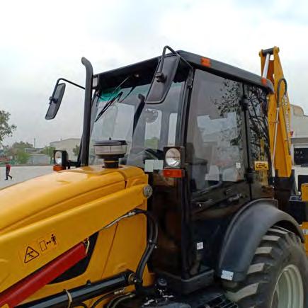
4.3 CAB
•Tinted safety glass – wide glazed surface giving total visibility •Operator’s seat with adjustable suspension.
4.4 MACHINE WEIGHT
Maximum authorised weight 7500 kg (16500 lb)
Shift Maximum authorised weight 6885 kg (151471 lb) Center Mount
4.5 TRANSMISSION
Torque converter
Two phase, integrated with engine flywheel.
Stall ratio
Gearbox Type
Travel speed
4.6 AXLES
2.88:1
Direction of travel control with 4 synchronized gears. 4 forward and 4 reverse gears. Electrical transmission cut-out using push button on the gear change lever. Speeds in forward and reverse with engine speed at 2200 rpm.
1. Fixed Rear Axle - Includes Planetary reduction gears and oil immersed disc brakes.
2. Oscillating Front Axle
4.7 TYRES SIZE
4.8 WHEEL TIGHTENING TORQUE
1. Front wheel nuts 300 Nm (220 lbf ft)
2. Rear wheel nuts 600 Nm (440 lbf ft)
4.9 BRAKES
1.Service Brake
Oil-immersed disc brakes mounted inboard, on the rear drive shafts. Hydraulic operation by brake pedal master cylinders, incorporating independent and compensating functions for site and highway use.
2.Parking Or Emergency Brake
Hand-lever and cables operated through a totally separate mechanical system to directly operate a large calliper type disc brake.
4.10 STEERING
Type
Turning circle - Turning circles are the same for both 4WD and 2WD machines
Outside front wheels, no brakes
Outside front wheels, with brakes
Outside bucket, no brakes
Outside bucket, with brakes
4.11 HYDRAULICSYSTEM
(1) Pump Tandem Pump
Hydrostatic
8.4 m (27’ 7”)
7.2 m (23’ 8”)
11.1 m (36’ 5”) 10.0 m (32’ 10”)
(2)Loader Control Valve
Two spool open centre multi block valve, incorporating circuit relief valves for head and rod sides of bucket and main lift cylinders. Single lever operation of bucket and lift spools plus a third spool for attachments, such as clamshell bucket. An optional three spool open centre valve is available. Where fitted, the additional spool can be used for attachments, such as clamshell bucket.
(3)Backhoe Control Valve
The backhoe control valve is a open centre 6 spool multi block valve. The six spool valve controls the digging functions through two control levers. Circuit relief valves protect the boom, dipper stick, bucket, swing, and additional spool cab be use for extendable dipper stick and auxiliary circuits. Optional 7 spool valve block is for Rock Breaker attachment or for Extendable Dipper attachment and 8 spool valve block is for Extendable Dipper with Rock Breaker. There are two additional levers for operating the stabilizer spools.
Solenoid valves operate the side shift clamp, (side shift backhoe) and optional digger bucket quick attach. A separate foot pedal is used to operate a spool for the optional extendable dipper stick or auxiliary circuit. A solenoid operated changeover valve is used to divert hydraulic flow to either the extendable dipper stick or the auxiliary spool.
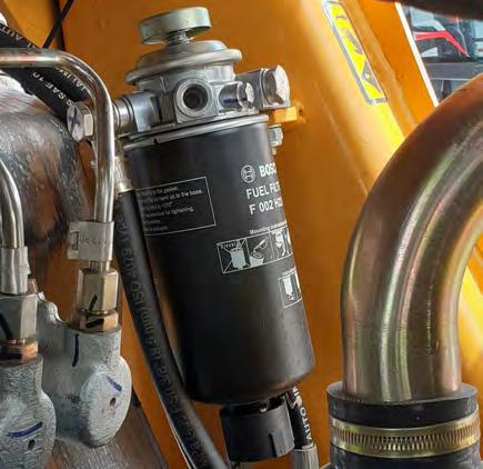
(4)Filtration
On return circuit, by spin on type filter.
4.12 Capacities
Note : Some dimensions will differ according to different tyre sizes, tyre pressures and loader bucket specifications.
Description
Table Of Contents
1. CAB DOORS
Note
Make sure that the doors are correctly closed before any travel.
• To lock the doors, use the key.
•The doors are opened with the handle (1) from the outside and with the lever (2) from the inside.
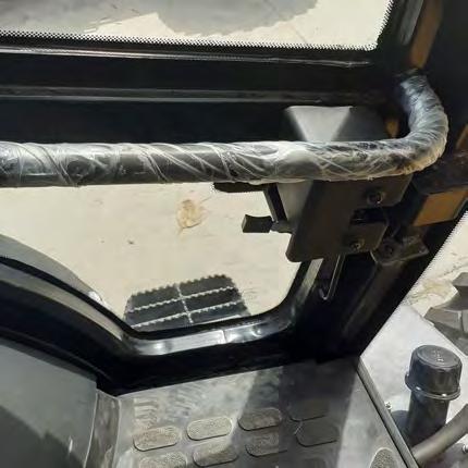
2. STEPS AND ACCESS HANDLES
Note
•Never use the steering wheel or the control levers to help yourself entering or leaving the operator’s compartment.
•Clean the steps and access handles and remove all traces of grease, oil, mud and ice (winter).
•Never jump down from the machine.
•When dismounting from the operator’s compartment always face the machine and use the steps and access handles.

•Use the left-hand side for entering or leaving the operator’s compartment.
•The right-hand side is only for use in emergency.
Use the steps (1) and access handle (2) when entering or leaving the operator’s compartment.

Instrument Panel
Note
1.SPEEDOMETER – The speedometer shows the machine speed.

2.LEFT TURN INDICATOR LAMP – This indicator lamp flashes when the indicator lever is moved forward.
3.INDICATOR LAMP FOR NEURAL – This indicator lamp comes on when the lever is in neutral position.
4.PARKING BRAKE INDICATOR LAMP – This indicator lamp comes on when the parking brake lever is engaged .
5.RIGHT TURN INDICATOR LAMP – This indicator lamp flashes when the indicator lever is moved backwards.
6.TRANSMISSION OIL TEMPERATURE WARNING LAMP - This warning lamp comes on when the transmission oil temperature is too high. If the warning lamp comes on when the machine is working, move the machine to a place of safety, stop the engine, engage parking brake, remove the starter key and find the cause of the problem.
7.HIGH BEAM INDICATOR LAMP – This indicator lamp comes on when head lights are on high beam.
8.ENGINE COOLANT TEMPERATURE WARNING LAMP - This warning lamp comes on when the engine cooling system reaches an abnormally high temperature. If the lamp comes on when the machine is working, move the machine to a place of safety, stop the engine, engage parking brake, remove the starter switch key and find the cause of the problem.
9.ENGINE OIL PRESSURE WARNING LAMP - This warning lamp comes on when the engine oil pressure is too low. If the lamp comes on when the machine is working, move the machine to a place of safety, stop the engine, engage parking brake, remove the starter switch key and find the cause of the problem.
3.2 Side Control Panel
Note
When the starter switch key is in the “On” position the warning lights (2) and (9) come on. If one or more do not come on, the bulbs must be replaced.
1. FUEL LEVEL GAUGE - This gauge shows the quantity of fuel in the fuel tank.
2. ALTERNATOR CHARGE WARNING LAMP - This warning lamp comes on when the alternator is not charging the battery. If the lamp comes on when the machine is working, move the machine to a place of safety, stop the engine, engage parking brake, remove the starter switch key and find the cause of the problem.
3. HYDRAULIC FILTER RESTRICTION WARNING LAMP - This warning lamp comes on when the hydraulic filter is clogged.
4. ENGINE TACHOMETER- The tachometer shows the engine speed in revolutions per minute. The figures indicated must be multiplied by 100.

5. HOURMETER – The hour meter shows the total number of hours for which the engine has been operated.
6. AIR FILTER CLOG INDICATOR -This warning lamp comes on when the air filter is clogged (Only for Perkins )
7. HYDRAULIC OILTEMPERATURE WARNING LAMP - This warning lamp comes on when the hydraulic oil temperature is too high. If the lamp comes on when the machine is working, move the machine to a place of safety, stop the en-gine, engage parking brake, remove the starter switch key and find the cause of the problem.
8. ENGINE COOLANT TEMPERATURE GAUGE - This gauge shows the temperature of the engine coolant. When the temperature is normal the needle is in the white area. If the needle is in the red area, move the machine to a place of safety, stop the engine, engage parking brake, remove the starter switch key and check the engine coolant level. Make sure that the radiator and oil cooler are perfectly clean and that all the thermostats function correctly.
9. TRIP RESET BUTTON- The trip of the machine becomes zero when this button is pressed.
4. OPERATOR’S COMPARTMENT CONTROLS

Note
Before starting the engine, make sure you are fully aware of the location and the function of each control. Operating the controls wrongly can cause serious physical injury.
4.1 IGNITION SWITCH
Located on the right of the operator’s seat (with seat in loader attachment position), this switch has three positions:
Key position
Position (0) : OFF
Position (1) : ON
Position (2) : START :
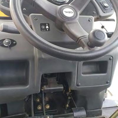
4.2 GEAR LEVER AND TRANSMISSION DUMP SWITCH
Note
Any uncontrolled movement of the machine can cause an accident. Before turning the operator’s seat to the backhoe attachment working position, it is essential for the direction of travel lever and the gear change lever to be placed in the neutral position and the parking brake engaged.
•Forward and reverse travel depends on the position of the FNR switch lever.

•Reduce engine speed before changing to a lower gear.
•Before stopping or starting the engine, make sure that the gear lever is in the neutral position (N).
•Before using the backhoe attachment controls, make sure that the lever is in neutral position (N).
•Located to the right of the steering wheel, the lever (A) enables four forward and four reverse gears to be selected.
Position (N) Neutral.
Position (1) First gear.
Position (2) Second gear.
Position (3) Third gear.
Position (4) Fourth gear.
All four gears are synchronized. All the ratios can be selected without stopping the machine. Before changing gear, press and hold the transmission dump button (B) located on the left-hand side of the lever. After changing the gear, release the button (B) to engage the clutch.
• If the gear change lever is in the neutral position, the machine cannot move forward or in reverse.

• Stop the machine completely before changing the direction of travel.
• Before stopping or starting the engine make sure that the lever is in the neutral position (0).
• Before using the backhoe attachment controls, make sure that the lever is in neutral position (0).
• If the lever is operated in forward or reverse travel while the parking brake is engaged (wheels braked), the audible warning device will sound. The parking brake lever must be released.
1. Located to the left of the steering wheel, this lever has three positions to select the direction of travel of the machine.

2. Neutral (0): In this position the machine cannot travel.
3. Forward (1): Raise and push the lever completely forward. In this position, the machine can travel forwards.
4. Reverse (2): Raise and pull the lever completely backwards. In this position the machine can travel in reverse and the audible warning device sounds.
Position (1)
4.5 DIRECTION INDICATOR LEVER, HORN AND LIGHTING SWITCH

Located to the right of the steering wheel, this lever has eight positions:
1.Position (0): The lever is in a neutral position.
2. Position (1): Rotate switch 90° towards operator, the side lights come on and the indicator lamp on the front control panel.

3.Position (2): Rotate a further 90°, the dipped headlights come on, with the side lights.
4. Position (3): With the switch in position (2), pull towards operator, the main beam comes on and the indicator lamp on the front control panel comes on. Pull again to turn main beam off.
5. Position (4): With the switch in positions (0) and (1), pull towards operator to flash main beam.
6. Position (5): Push the end of the lever to operate the horn.
7. Position (6): Pull the lever down to operate the right direction indicators and the indicator lamp on the front control panel.
8.Position (7): Push the lever up to operate the left direction indicators and the indicator lamp on the front control panel.
4.6 STORAGE AREAS AND COMPARTMENTS
4.7 TOOL BOX
Located on the left-hand side of the cab, this storage compartment is intended to contain a first aid kit and the documentation pack.

Located on the roof lining, this light is controlled by a switch incorporated in the lamp base.

4.9 STEERING COLUMN TILTING LEVER
Note
It is essential that the machine to be brought to a complete halt before attempting to adjust the steering column tilt position. If this instruction is not observed an accident may occur.
4.10 ENGINE ACCELERATOR PEDAL

NOTE
Never use this pedal when working with the backhoe attachment.
This pedal is coupled with the engine throttle lever. Before using the pedal, make sure that the throttle lever is in the minimum speed position.
•Located under the steering wheel, this pedal enables the engine speed to be increased or decreased.
Maximum speed : Press the pedal fully down. Idle speed : Release the pedal.
•This pedal is used for travel and for operating the loader attachment.
4.11 BRAKE PEDAL

NOTE
Never use this pedal when working with the backhoe attachment.
•Check the correct braking of the machine regularly.
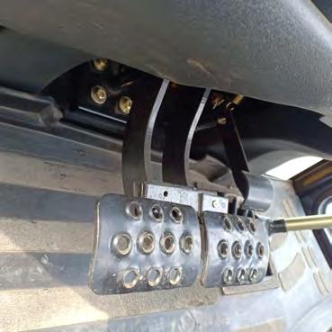
•Located under the steering wheel, these two pedals are equipped with a plate which enables them to be locked together or unlocked. This enables the machine either to be braked (pedals locked) by pressing either of the pedals or to be turned (pedals unlocked) to the right by pressing on the right-hand pedal or to the left by pressing on the left-hand pedal.
4.12 LOCKING AND UNLOCKING THE BRAKE PEDALS
NOTE
It is mandatory to make sure that the brake pedals are locked together before any road travel or travel in third or fourth gear. If this instruction is not observed an accident may occur.
Locking and unlocking of the pedals is done by means of a hinged pin (1) which locks the pedals together or unlocks them.
To unlock the brake pedals-
Raise the pin, slide it to the right and then turn it downwards to lock it. The two pedals are now independent.
This position must be used only on the job site.
To lock the brake pedals
Raise the pin, slide it to the right and then turn it downwards to lock it.
It is mandatory to use this position for road travel or when traveling in third or fourth gear.
4.13 ENGINE THROTTLE LEVER
Located on the RH console, lever is used to increase or decrease the engine speed .
Position (1) Idle speed.
Position (2) Maximum speed.
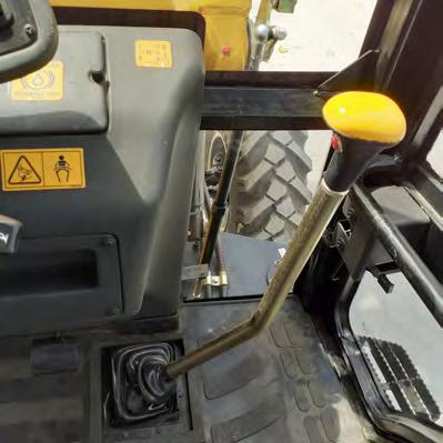
4.14 PARKING BRAKE LEVER
Note
Anyuncontrolledmovementofthemachinecan cause an accident. Before turning the operator’s seat to the backhoeequipmentworkingposition, it is essential for thedirectionoftravelleverandthegearchangeleverto beplacedintheneutralpositionandtheparkingbrake engaged.
Whentheparkingbrakeisengaged,theaudiblewarningdevicesoundsifthedirectionoftravelcontrolleverisnotin theneutralposition.
Nevertrytomovethemachinewhentheparkingbrakeisengaged. Beforestoppingtheenginemakesuretheparkingbrakeisengaged. Before using the backhoe attachment controls, make surethattheparkingbrakeisengaged. Theparkingbrakecanalsobeusedasanemergencybrakeintheeventofamainbrakesystemfailure.
Located on the right of the operator’s seat (with the seat in the loader attachment position), this lever enables the machine to be parked securely. Raise the lever to engage the parking brake. In this position, the indicator lamp lights up on the front control panel. Lower the lever to free the machine (wheel brakes released). In this position, the indicator lamp on the front control panel goes out.
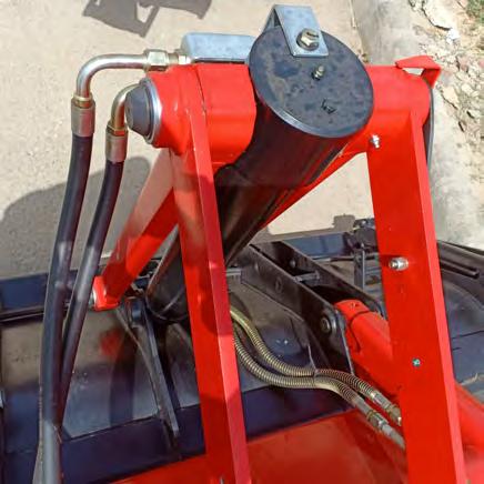
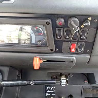
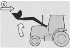
4.15 BOOM UNLOCKING LEVER
Located at the right of the operator's seat (with the operator’s seat in the loader attachment position) this lever enables the operator to lock or unlock the boom. It is recommended to lock the boom during road travel.

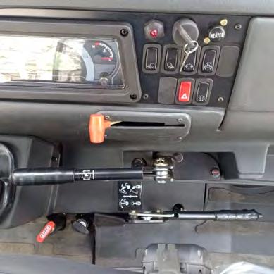
To lock the boom in transport lock casting (2) ,pull the lever (1) upwards . To unlock , push down the lever (1).
4.16 FM RADIO & MUSIC PLAYER

4.17 MOBILE CHARGING POINT
Switches


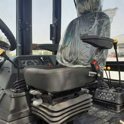
5.OPERATOR’S
NOTE
Before using the controls, make sure that the seat is adjusted and positioned correctly
To operate the machine correctly with maximum efficiency and comfort, the seat should be correctly adjusted to suit the height and weight of the operator.

5.1 Seat Rotation

Hold the lever (1), rotate the seat until the desired position is reached and then release the lever.
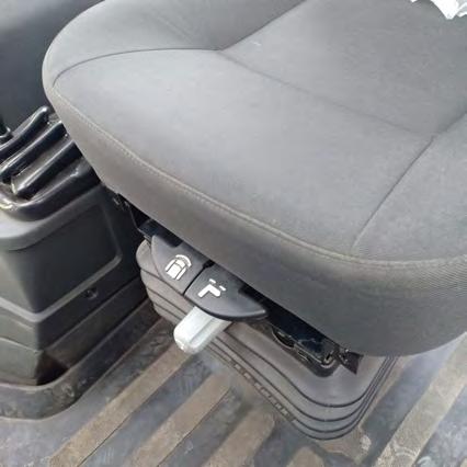
5.2 Forward, Rear and Swivel Adjustment
Hold the lever (2) to the top, slide the seat forward /backward until the desired position is reached and then release the lever.
To turn the seat, hold the lever to the top, slide the seat to the rear and turn it. Release the lever and make sure that the seat is correctly locked in position.
5.3 Seat Back Rest Adjustment

To adjust the seat back rest, push the lever (3) downwards, swivel the back rest to obtain the desired position and then release the lever.
5.4 Seat Belt
Note
Always fasten your seat belt before starting the engine. The seat belt will protect you efficiently if you attach it correctly and if you always wear it. The seat belt must not be too loose. It must not be twisted or caught in the seat
Sit comfortably on the seat. Pull a surplus length of belt (4) out of the reel, and buckle it at (5). Allow the excess belt to retract back into the reel.
5.5 Seat Up, Down & Suspension Adjustment
Rotate the knob (6) clockwise /counterclockwise to adjust the suspension of the seat.
6. LOADER CONTROLS
Note
•Before starting the engine, make sure you are fully aware of the location and the function of each control. Operating the controls wrongly can cause serious physical injury.
•Before using the controls make sure that the operator’s seat correctly adjusted in the loader attachment position.
•Engine rpm to be set manually with the hand throttle. •A decal located to the right of the lever explains the function of each control.
6.1 With Standard Loader Bucket
Located on the right-hand side of the cab (with the operator’s seat in the loader attachment position), this seven position lever operates the loader attachment controls. The speed of movement of each control depends on the tilting angle of the lever.

6.2 Transmission dump switch on loader lever

Gear box comes in neutral if the dump switch is pressed. This dump switch is provided on the loader control lever for the ease of operator. There is one more dump switch fitted on the gear lever as shown in sub-section 4.2.
7. OPERATION OF THE LOADER CONTROLS
7.1 Neutral
When the lever is in neutral position (0) the loader beam and bucket will not move. The lever is spring loaded to neutral position (0) and will automatically return to this position when released, movement of the loader beam and/or bucket will stop.
7.2 Raising /Lowering of the Loader Beam
Raise
To raise the bucket to position A, pull the loader lever straight back (1). As the bucket rises, it will stay at the same angle to the ground. This is due to the self leveling mechanism.
Lower
To lower the bucket to position B, push the lever forward (2). The bucket will stay at the same angle to the ground due to self leveling mechanism.
7.3 Filling/Dumping the Loader Bucket
Roll Back- With the lever position at 3 , the bucket rolls back in position D.
Roll Forward- Bucket rolls forward to position C if the lever is pushed to position at 4.
7.4 Loader Bucket Float Control
NOTE
In this position the lever does not automatically return to neutral when it is released. It is necessary to move it manually.
Float
With the lever in position (5), the bucket follows the contours of the ground without it being necessary to operate the lever. In this condition the bucket is free to ride up and down over the ground as the machine travels.
7.5 Automatic Loader Bucket Leveling
With the lever in position (6), the loader beam raises and simultaneously the loader bucket remains in the level position.
7.6 7 in 1 Loader Bucket Clamshell Control (Optional)
Located at the right-hand side of the cab (with the operator’s seat in the loader attachment position), this three position lever operates the opening and closing of the 7 in 1 loader bucket clam.
7.7 Neutral and Hold
Position (0): Neutral/hold. As soon as the lever is released, it automatically returns to the neutral position (0) and the clam remains in the position where it was when movement stopped.
Note
•Before starting the engine, make sure you are fully aware of the location and the function of each control. Operating the controls wrongly can cause serious physical injury.
•Any uncontrolled movement of the machine can cause an accident. Before turning the operator’s seat to the backhoe attachment working position, it is essential to place the direction of travel control lever and the gear change lever in the neutral position or the transmission control lever in the neutral position (power shift only), the parking brake engaged and lock the loader attachment controls (if equipped).
•Before using the backhoe controls, make sure that the operator’s seat is correctly adjusted in the backhoe attachment position.
Open Clam
To open the clam (position E), push the lever forward at position (1).
Close Clam
To close the clam(position F) , pull the lever back at position (2).
8 Operation Of The Backhoe Controls Note
•Before starting the engine, make sure you are fully aware of the location and the function of each con-trol. Operating the controls wrongly can cause seri-ous physical injury.
•Any uncontrolled movement of the machine can cause an accident. Before turning the operator’s seat to the backhoe attachment working position, it is essential to place the direction of travel control lever and the gear change lever in the neutral position or the transmission control lever in the neutral position (powershift only), the parking brake engaged and lock the loader attachment controls (if equipped).
•Before using the backhoe controls, make sure that the operator’s seat is correctly adjusted in the back-hoe attachment position.
•Whenever the backhoe attachment is used, it is mandatory for the machine to be resting on the sta-bilizers.
• A decal located in front of levers explain the function of the controls.
• Control levers are used to operate the backhoe attachment. The speed of movement of each control depends on the angle to which the lever is tilted.

8.1 Boom and Swing Left-Hand Control Lever
This lever has five positions:
Position (0)
Neutral/hold. This position enables the attachment movement to be stopped. As soon as the lever is released, it automatically returns to the neutral position (0) and the attachment remains in the position where it was when movement stopped.
Position (A)
Position (B)
The backhoe boom rises.
The backhoe boom lowers.
Position (C)
Position (D)
The backhoe attachment swings to the right.
The backhoe attachment swings to the left.
8.2 Dipper and Backhoe Bucket Right-Hand Control Lever
This lever has five positions:
Position (0)
Neutral/hold This position enables the attachment movement to be stopped. As soon as the lever is released, it automatically returns to the neutral position (0) and the attachment remains in the position where it was when movement stopped.
Position (E)
Position (F)
The backhoe dipper extends.
The backhoe dipper retracts.
Position (G)
Position (H)
The backhoe bucket digs (crowds).
The backhoe bucket dumps.
8.3 Extendable Dipper/ Auxiliary Hydraulic Control Pedal (Optional)


This pedal operates extendable dipper. This pedal has three positions:
Position (0)
Position (J)
Position (K)
Neutral position
The extendable dipper extends.
The extendable dipper retracts. Before using this pedal make sure that the extendable dipper is mechanically unlocked.
To unlock the extendable dipperStep 1- Remove the lynch pin (1) Step 2- Remove the licking pin (2).

Note
•Any uncontrolled movement of the machine can cause an accident. Before turning the seat to the backhoe attachment working position, it is essential to place the direction of travel control lever and the gear change lever in the neutral position, the parking brake engaged and lock the loader attachment controls (if equipped).
•Before using the stabilizer controls, make sure that the operator’s seat is correctly adjusted in the backhoe attachment position.

•Before moving the stabilizers make sure that no person is within the working range of the stabilizers.
•Whenever the backhoe attachment is used the machine must be resting on the stabilizers.
•Before machine travel or before using the loader attachment,make sure that the stabilizers are completely raised.
• Two decals explains the function of the controls.
• To raise or lower the stabilizers at the same time, operate the two levers simultaneously
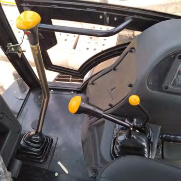
9.1 Right-Hand Stabilizer Control Lever
This lever has three positions :
Position (0)
Neutral. This position stops the movement of the right-hand stabilizer. As soon as the lever is released, automatically returns to the neutral position (0) and the right-hand stabilizer stops raising or lowering.
Position (L)
Position (M)
The right-hand stabilizer lowers (position A).
The right-hand stabilizer rises (position B).
9.2 Left-Hand Stabilizer Control Lever
This lever has three positions:
Position (0)
Neutral. This position stops the movement of the left-hand stabilizer. As soon as the lever is released, it automatically returns to the neutral position (0) and the left-hand stabilizer stops raising or lowering.
Position (L)
Position (M)
The left-hand stabilizer lowers (position C).
•During road travel, the stabilizers must be completely raised. D B
The left-hand stabilizer rises (position D). C A
It is located inside the cabin, the tool box is used for storing essential parts and tools required for servicing operations. The tool box cover is cushioned , it can be used as a helper seat.

OPERATOR’S COMPARTMENT WINDOWS 11.
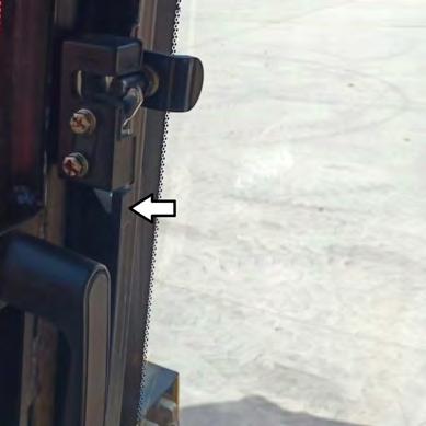
11.1 Opening Side Window
From the closed position, push the lock lever (1) inwards to unlock, then swing the window outwards by holding the handle (2) and ensure that the window is locked in full open position.

11.2 Closing of Side Windows
From the open position, pull the window inside holding the handle (2) and ensure that the window is locked in closed position.
11.3 Opening and Closing the Rear Window
To open the rear window, take a firm grip on the two handles A and press lever B on both sides to release the lock mechanism.
Pull the window towards the front of the machine and up as far as it will go Release lever B then make sure the window latches in the open position.

To close the window, press lever B on both sides to release the lock mechanism then lower the window to the closed position. Release lever B then push the window down with a little extra effort holding the handle C to ensure that window is locked .
12. REAR VIEW MIRRORS
Make sure the rear view mirrors are correctly adjusted before driving the machine.
13. FUEL TANK
•Clean around the filler cap before re-fuelling.
•In cold weather, use fuel corresponding to the ambient temperature.
•In cold weather, fill the tank after each working day, to prevent the formation of condensation.
•The fuel cap can be locked by a key.
NOTE
Fill the fuel tank to the maximum marks to avoid the formation of condensation.
Located
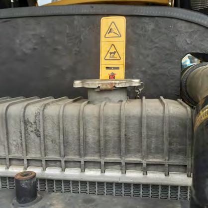
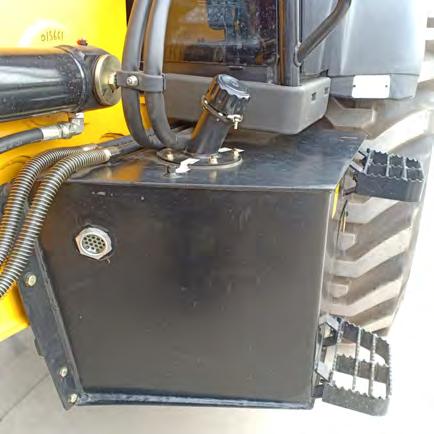
14. HYDRAULIC TANK
•Clean around the filler cap (1) before refilling.
•Use a suitable hydraulic fluid.
•When installing the cap, make sure that it is correctly placed in the notches and lock it by turning clockwise until it stops.
•Located in left side of the machine the capacity of the reservoir is 90 liters.
•The sight glass (2) shows the level of fluid in the reservoir.
15. BATTERY DIS-CONNECT SWITCH
Note
The battery should be disconnected using battery disconnect switch after each working day, during maintenance operations, for any service work on the electrical system and when leaving the machine unattended.

•Located on the battery box of the machine, the battery dis-connect switch is used to disconnect the battery completely from the electrical system.
•When the battery dis-connect switch is in position (1), the circuit is dis-connected.
•Rotate the switch anti-clockwise to bring it at position (2) to connect.
16.BATTERY BOX
17. LOADER ATTACHMENT SAFETY STRUT


NOTE
17.1 Locked Position
- Raise the loader attachment completely, stop the engine, engage parking brake and remove the ignition key.
- Remove the hair pin (1) and “U” bar (2).
- Place the strut on the cylinder rod and install the pin and “U” bar in the holes in the strut.
17.2 Unlocked Position
Note
Before lowering the loader attachment, make sure that the engine bonnet is closed.


1. Remove the hair pin (1) and “U” bar (2).
2. Swing the strut against the lift arm and install the pin and “U” bar in the holes in the strut and the retaining lug (3).
3.Start the engine and lower the loader attachment.
18. Engine Bonnet
Note
It is essential to install the loader attachment safety strut before any servicing work is carried out on the engine.
•Pull the lever (1) to open the engine bonnet (2) .
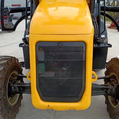
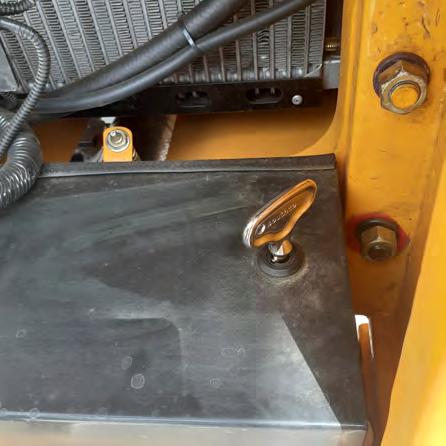
19. ACCESSING THE BATTERY
•Unlock the grill lock (1) by turning the key in counter clock direction .
•Remove the Bonnet Grill (2)

•Unlock the battery cover plate lock (3) with key (4) .
•Key is provided with the machine keys .
•Battery is secured by 2 J-bolts (5) and L-bracket (6) .
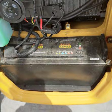


20.BATTERY
•Disconnect the battery isolator switch
Note
•When disconnecting the battery cables, always dis-connect the negative cable (-) first.
•When reconnecting the battery cables, always connect the negative (-) cable last.
•Never short-circuit the battery terminals with metal objects.
•Do not weld, grind or smoke near a battery.
•Batteries produce explosive gases. Keep away any flame, spark or cigarettes.
•Always provide good ventilation when charging a battery or using a battery in an enclosed space.
•Always protect your eyes when working near a battery.
21.
•Before replacing fuses, disconnect the battery disconnect switch.
•Never replace a fuse with one of a different amperage.
•Main fuse box is next to the battery and secondary fuse/ relay board is located at the front of the side console. Remove the cover plate to gain access to the fuses and relays.
23. TOOLS
The machine is supplied these tools which are located in the tool box :
•1 Grease gun
•1 Hammer
•1 Tool Kit