4 minute read
Section 7.Component Procedures
Model 9600/9700 Swing-Reach ® Lift Truck
Flow LimitersHydraulic Components
Flow Limiters
Main Mast Removal
1.Elevate the carriage approx. 3 ft. (1 m). Block and clamp between edge of carriage and baseleg. See “Blocking the Carriage” and Figure2-6 on page2-10.
2.Turn the key switch OFF and disconnect the battery connector.
3.Place a drain pan beneath the main lift cylinder hydraulic fitting.

4.Remove the hydraulic hose. Remove the flow limiter fitting.
Mini-Mast Removal
1.Elevate the load handler approx. 3 ft. (1m). Block and clamp the load handler. See “Blocking Load Handler” and Figure2-7 on page2-10
2.Turn the key switch OFF and disconnect the battery connector.
3.Place a drain pan beneath the mini-mast lift cylinder hydraulic fitting.
4.Remove the hydraulic hose. Remove the flow limiter fitting.
Installation
1.Insert the new flow limiter fitting.
2.Install the hydraulic fitting and hose.
3.Reconnect the battery connector and turn the key switch ON.
4.Lift the carriage, remove the blocking, then lower the carriage completely.
5.Bleed the lift system as necessary. See “Bleeding the Hydraulic System” on page7-74.

6.Check hydraulic fluid level.
Installation
1.Insert the new flow limiter fitting.
2.Install the hydraulic fitting and hose.
3.Reconnect the battery connector and turn the key switch ON.
4.Lift the load handler, remove the blocking, then lower the load handler completely.
Publication: 1089040, Issued: 08 Apr 2016
Model 9600/9700 Swing-Reach ® Lift Truck
Section 7.Component Procedures
Hydraulic Components Flow Limiters
5.Bleed the lift system as necessary. See “Bleeding the Hydraulic System” on page7-74.
6.Check hydraulic fluid level.
Publication: 1089040, Issued: 08 Apr 2016
7-85
Section 7.Component Procedures
Model 9600/9700 Swing-Reach ® Lift Truck
Main MastMast, Chain, Hose, Cable
Main Mast
Separating Tractor and Mast
Perform this procedure with a minimum of two technicians in a shop suitably equipped with a 10-tonhoist.
1.Retract and center the forks. Lower the load handler and operator platform completely.
2.Turn the key switch OFF and disconnect the battery connector. Remove the battery with a suitable battery removal device. Remove battery rollers.
3.Remove the forks.
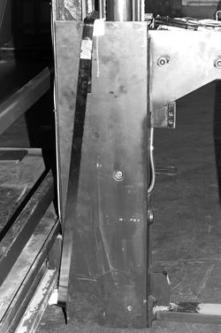
4.Secure the load handler: a.If there is a hole through the load handler near the bottom, insert a long bolt and nut so that the bolt secures the load handler. See Figure7-99 b.If there is no hole through the load handler, use steel banding (1.25x0.031in.) around the bottom of the mini-mast. See Figure7-100.

5.Insert 1 x 4 in. (2.5 x 10 cm) wood stringers cut to fit between lower traverse bearing and traverse stops on each side of the load handler. Secure with cable ties around the lower traverse rack.
6.Tape a 2 x 4 x 7 in. (5 x 10 x 18 cm) wood block between the mini-mast and the mini-mast lift cylinder at the midpoint of its height.
7.Disconnect four hydraulic hoses between the tractor and mast at the bottom of the battery compartment. Save the O-rings and cap/plug hose fittings.
8.Unplug all mast-to-tractor and wire guidance cable connections. Label for re-connection if necessary. See Figure7-101.

Publication: 1089040, Issued: 08 Apr 2016
Model 9600/9700 Swing-Reach ® Lift Truck
Section 7.Component Procedures
Mast, Chain, Hose, Cable Main Mast
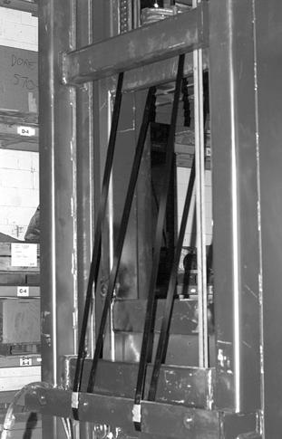
9. Model 9600: Attach two straps from a 10-ton hoist around the main mast and telescopic crossties. See Figure7-102
10. Model 9700: Attach two straps from a 10-ton hoist around the second main mast and telescopic crossties. See Figure7-102
On a Model 9700 mast, do not wrap hoist strap around the uppermost crosstie, only the main mast and telescopic crossties.
Note Routing of Straps
11.Block the tractor where it meets the mast. See Figure7-103.
12.Loosen the diagonal support arm jam nuts and remove the upper mounting bolts.
13.Remove the snap ring from the support arm clevis pin.
Each support arm weighs approx. 60lbs. (27 kg).

14.Using a helper, remove the clevis pin while supporting the support arm. Remove the arm. Replace the clevis pin and snap ring (so as not to misplace them).
Before loosening mast mounting bolts, make sure the weight of the mast is fully supported by the hoist (or lift trucks) and the tractor is blocked where it meets the mast.
15.Remove eleven mounting bolts and washers (4 at top, 7 at bottom) joining the tractor and mast at the tractor front bulkhead inside the battery compartment.

16.Supporting the weight of the mast with the hoist (or lift trucks), separate the mast from the tractor.

17.Disconnect connector JPA1 at the Supplemental Operator Display. Remove glass or mesh mast guard. Package and seal guard and Display in protective cardboard.
Publication: 1089040, Issued: 08 Apr 2016 7-89
Section 7.Component Procedures
Model 9600/9700 Swing-Reach ® Lift Truck
18.Install steel banding around the overhead guard and bottom main frame crosstie as shown.


19.Protect removed electrical cable connectors with a plastic bag and cable tie.
NOTE: Be
Publication: 1089040, Issued: 08 Apr 2016
Main MastMast, Chain, Hose, Cable 7-90
Model 9600/9700 Swing-Reach ® Lift Truck
Section 7.Component Procedures
Mast, Chain, Hose, Cable Main Mast
Joining Tractor and Mast
Refer to Swing-Reach ® Lift Truck Installation Guide P/N 1169846.
21.Lower the upper end of the mast onto a suitable dolly or skid.
22.Using a 10-ton-capacity hoist, elevate the main frame at the platform and lower it unto a suitable dolly or skid.
23.To prevent over-the-mast hoses and cables from movement during transport, secure hoses and cables to main lift cylinders with cable ties at two or more points on each cylinder. Attach a “toe-tag” to the lift/lower control with a reminder to remove these cable ties at installation.
24.If the mast is placed on a skid, secure the mast tightly to the skid with steel banding around mast and inner telescopic crossties, at four places.
25.Reposition static straps so they do not protrude from the bottom of the mast during transport.
26.For tractor shipment, remove tractor side covers and tape them securely inside the battery compartment.
27.Securely tape the packaged mast guard and Supplemental Operator Display inside the battery compartment.
28.Install battery gates. Place the carton with the battery rollers in the battery compartment. Install steel banding around the bottom of the battery compartment, through the handles of the battery gates, and over the carton on both sides.

29.Immobilize control handles and steering tiller by wrapping with protective plastic tape.
Publication: 1089040, Issued: 08 Apr 2016 7-91


