8 minute read
Section 7.Component Procedures
Model 9600/9700 Swing-Reach ® Lift Truck
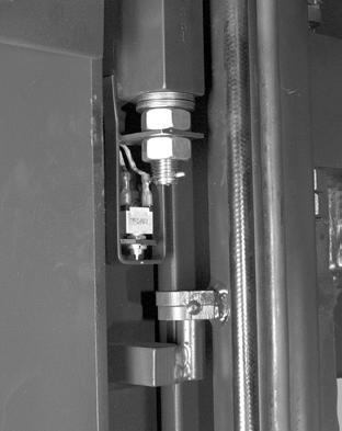
Mini-Mast Height Proximity SensorElectrical Components
position. Feed the lift chain and attach the chain anchor to the mini-mast.
9.Loop over-the-mast hoses and electrical cable over their pulleys and reattach the pulley bracket cover.
10.Reconnect the battery connector and turn the key switch ON.
11.Slowly raise the load handler to remove slack in over-the-mast hoses and cable. Remove blocks and lower the load handler completely. Remove the temporary cable tie securing the electrical cable to the turret. Attach the load handler turret cover and traverse motor cover.
12.Reinstall the forks. Check and adjust the fork height. See “Fork Height and Lift Chain Adjustment” on page7-114.
13.Adjust the mini-mast cylinder pucks. See “Mini-Mast Pucks” on page7-112.
Checking the Height Sensor Assembly
Check the following before reinstalling the Mini-Mast Height Sensor Assembly:
1.Make sure the sensor is fully seated in the sensor housing.
2.Check for compression of the wave spring when the sensor housing is at rest in the mounting bracket. The sensor housing should be fully extended from the bracket and the wave spring should be slightly compressed. If not, bend the circular tab on the back of the mounting bracket toward the sensor until the wave spring is slightly compressed.
3.Insert the sensor in the sensor housing. Insert the sensor housing, housing side out, with the wave spring on the inside, into the mounting bracket. To prevent the sensor assembly from sliding out of the bracket, secure it with the screw, washer, and fender washer in the threaded hole in the edge of the bracket.
Publication: 1089040, Issued: 08 Apr 2016
Model 9600/9700 Swing-Reach ® Lift Truck Section 7.Component Procedures
Electrical Components Rotate Position Feedback Pot (VR6)
Rotate Position Feedback Pot (VR6) Removal
1.Turn the key switch OFF and disconnect the battery connector.
2.Remove the load handler turret cover.
3.Cut cable ties on the potentiometer cable, noting their location for later installation.
4.Disconnect the cable harness at JP4 under the turret.
5.Loosen the set screw in the bracket and remove the potentiometer. See Figure7-82 .
Figure 7-82.Rotate Position Feedback Pot
Installation
1.Position the potentiometer assembly over the locating pin and mounting bracket. Adjust the bracket on the actuator plate so the potentiometer is centered. Tighten the set screw.
2.Route the cable harness and install new cable ties.
3.Connect JP4 under the turret.
4.Reconnect the battery connector and turn the key switch ON.
5.Adjust the potentiometer. See “Adjustment” .
6.Run Learn for load handler. See “Learn Ld Hndlr (Load Handler)” on page3-22.
7.Install the load handler turret cover.
Adjustment
If the pot mounting bracket is not adjusted correctly, lift truck travel speed may be limited. To adjust the bracket:
1.Rotate the forks so they point straight ahead.
2.Adjust the potentiometer mounting bracket so it is centered fore-aft inside the rotate actuator.
3.Place a combination square against the flat sides of the mounting bracket.
4.Adjust the bracket left or right until it is centered in the mounting plate.
5.Refer to “TestA88–Rot Posn [Rotate Position Feedback Pot (VR6)]” on page6-66 and set the potentiometer voltage at 2.5V with the forks straight ahead.
6.Run Learn for load handler. See “Learn Ld Hndlr (Load Handler)” on page3-22
Publication: 1089040, Issued: 08 Apr 2016 7-63
Section 7.Component Procedures
Model 9600/9700 Swing-Reach ® Lift Truck
Traverse Position Feedback Pot (VR5) Removal
1.Traverse the mini-mast so it is against the stop on the right side. Lower the operator carriage and load handler completely.
2.Use a work platform, ladder, or other suitable device to gain access to the Load Handler manifold on top of the overhead guard.
3.Remove the cover over the manifold and traverse motor. See Figure7-83 .
2. Correct routing of the cable is important. Do not attach to hoses or other cables with cable ties. Do not wrap the cable around other hoses or cables such that the cable would tug on the pot.
3.Reconnect the wiring harness at connector JPK2.
4.Reconnect the battery connector and turn the key switch ON.
5.Refer to “TestA86–Trv Posn [Traverse Position Feedback Pot (VR5)]” on page6-64 and set the potentiometer voltage at 4.4V.
6.Position the pot over the locating pin. Make sure the wires of the pot are not touching, rubbing, or pressing on the locator pin. Tighten the set screw holding the pot shaft.
7.Refer to “TestA86–Trv Posn [Traverse Position Feedback Pot (VR5)]” on page6-64 and verify voltages are correct for full left and full right traverse.
8.Install the cover over the manifold and traverse motor.
9.Run Learn for load handler. See “Learn Ld Hndlr (Load Handler)” on page3-22
4.Traverse very slowly until the set screw on the pot shaft is accessible.
5.Turn the key switch OFF and disconnect the battery connector.
6.Loosen the set screw holding the pot shaft. Cut the cable tie.
7.Disconnect the pot wiring harness at JPK2.

8.Lift the pot assembly off the locating pin.
Installation
1.On the new potentiometer assembly, make sure the pot is turned so the terminals are at approx. a 45° angle from the slot in the mounting plate. If not, cut cable tie, loosen nut, align pot, tighten nut, and install a new cable tie.
Publication: 1089040, Issued: 08 Apr 2016
Traverse Position Feedback Pot (VR5)Electrical Components 7-64
Model 9600/9700 Swing-Reach ® Lift Truck
Electrical Components
Slack Chain Switch Adjustment
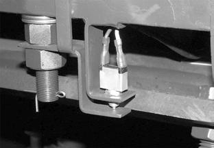
A slack chain switch is mounted on each of the main lift chain upper chain anchors.


Section 7.Component Procedures
Slack Chain Switch Adjustment
Do not block against the platform floor, use the edge of the platform. Do not block the carriage against the floor — lowering the platform could tip the load wheels off the floor.
3.Continue to hold the lower control for at least 5 seconds.
4. Model 9600 : Adjust the switch mounting bracket up or down so that the switch is open.
5. Model 9700 : Turn the locking nut on the shaft of the switch to adjust the switch on the mounting bracket. Continue turning the locking nut until the switch is open.
1.Verify the switch is firmly in the normally closed position.
2.To adjust the switch, lower the raised platform onto a block.
Publication: 1089040, Issued: 08 Apr 2016
7-65
Section 7.Component Procedures
Model 9600/9700 Swing-Reach ® Lift Truck
Cold Storage Conditioning
NOTE: Conversion for cold storage operation requires prior Raymond approval via Form S207.
Lift trucks operating in a cold storage environment require the following:
Components Required
•Cold storage control handle assemblies with heaters
•Wire mesh mast guard
Lubricants
See the “Lubrication Specification Chart” on pageA-2 for special hydraulic fluid and drive unit lubricants for cold storage operation.
NOTE: Do not add any additive to this hydraulic fluid.
Grease carriage fittings and coat battery roller shafts with all-weather grease (P/N1012992).
Corrosion Inhibitor Coating
Coat or spray bare metal surfaces listed below with Corrosion Inhibitor Coating (P/N990-644):
•Main and mini lift chain pulleys and shafts
•Main and mini lift chain anchors and threaded pins
•Drive unit dipstick
Publication: 1089040, Issued: 08 Apr 2016
Cold Storage ConditioningElectrical Components 7-66
Section 7.Component Procedures
Model 9600/9700 Swing-Reach ® Lift Truck
Lift/Lower PumpHydraulic Components
Lift/Lower Pump
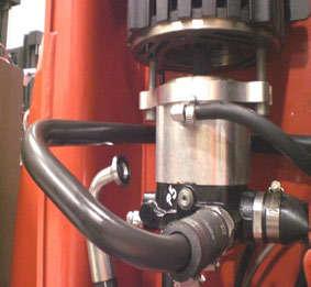
The lift/lower pump assembly includes an integral manifold. The lift/lower solenoid (SOL1) and lift pressure relief valve (REL-1) are located on this manifold. Refer to “Manifold Port Torque Specifications” on page7-73 when replacing these components.
Fill the lift/lower pu mp completely with oil (prime) before operation.
Pump Maintenance
Lubricate the pump spline shaft every 180 days or 500 Deadman Hours. It is not necessary to completely remove the pump.

1.Turn the key switch OFF and disconnect the battery connector.
2.Remove pressure hose from side of pump.
3.Remove return line (metal tubing) mounting hardware as necessary to allow pump to be lowered. Loosen one hose clamp and remove the second clamp.
4.Remove pump mounting screws and temporarily install longer screws (M12 x 60mm shown). Install screws to just catch on a few threads of motor holes. See Figure7-86
5.Drop pump onto screw heads to provide access to spline.
6.Clean, inspect, and lubricate spline shaft with molybdenum anti-seize compound (P/N1223184).
7.Reassemble. Apply thread-locking compound (P/N1013829) to mounting bolts and torque to 55ft. lb. (75 Nm).
8.Open Emergency Lower Valve. Lift for 10 seconds to purge any air, then close valve. Re-key and lift to clear height errors.
9.Bleed hydraulic system. Refer to “Bleeding the Hydraulic System” on page7-74
Removal
1.Remove filter cap and allow oil to drain out of filter.
2.Clamp suction hose and disconnect from pump.
3.Clamp case drain hose and disconnect from pump.
4.Disconnect return line tube assembly from pump.
5.Loosen jam nut on manifold inlet fitting, P2. Remove pressure hose from pump.
6.Disconnect wires at SOL1.
7.Remove pump from truck.
Installation
1.Make sure the pump is filled with oil before installation.
a.Hold pump with suction inlet facing up.
b.Press check valve to inspect cavity. Cavity should be completely filled with oil.
c.Add oil if cavity is not completely filled.
2.Lubricate spline shaft with molybdenum anti-seize compound (P/N1223184).
3.Install pump. Apply thread-locking compound (P/N1013829) to mounting bolts and torque to 55ft. lb. (75 Nm).
4.Connect all hoses. Connect SOL1 coil wires.
5.Open Emergency Lower Valve.
7-68
Publication: 1089040, Issued: 08 Apr 2016
Model 9600/9700 Swing-Reach ® Lift Truck
Hydraulic Components
6.Reconnect the battery connector and turn the key switch ON.
7.Request lift for 10 seconds.
NOTE: The first rotation of the lift motor and pump should be in the lifting direction. Do not attempt to lower. Code 64 or 67 is displayed during lift (truck sees motor rpm with no change in lift height). Lift rpm is limited.
8.Close Emergency Lower Valve.
9.Request lift. Continue lifting until system fills and mast elevates. Oil level in reservoir can be observed going down. Elevate both main and mini lift cylinders.
10.Bleed the main and mini lift cylinders. Refer to “Bleeding the Hydraulic System” on page7-74 .
11.Lower carriage and re-key to clear code.
12.Lift carriage and load handler to clear height error.
13.Check and fill reservoir.
14.Check lift pressure and adjust if necessary. Refer to “Lift Pressure Adjustment” on page7-76
15.Run TestO62–Lower Sol [Lower Solenoid (SOL1)] (Page6-157) .
Section 7.Component Procedures
Lift/Lower Pump
Publication: 1089040, Issued: 08 Apr 2016 7-69
Section 7.Component Procedures
Model 9600/9700 Swing-Reach ® Lift Truck
ManifoldsHydraulic Components
Manifolds
Main Manifold
The main manifold, located in the tractor compartment on the lower left, controls main and mini-mast lift/lower functions and provides hydraulic fluid to the load handler manifold. It
Figure
SOL4 - Main Lift Select
SOL3 - Main Load Hold
SOL5 - Mini Load Hold also contains a pressure relief valve for the load handler. See Figure7-87 . Refer to “Manifold Port Torque Specifications” on page7-73 when replacing components on this manifold.
SOL6 - Mini Lift Select
REL-2 Load Handler Relief
P2 - To/From Lift Pump
Emergency Lower Valve
G1 - Main Pressure Transducer
TP1 - Main Lift Pressure Port
T2 - Load Handler Return (via OTM hose)
7-70
G2 - Mini Pressure Transducer
A2 - To Load Handler Manifold (via OTM hose)
TP2 - Mini Lift Pressure Port
C2 - To Mini Lift Cylinders
C1 - To Main Lift Cylinders
TP3 - Load Handler Pressure Port
A1 - From Load Handler Pump
T1 - Load Handler Return
Publication: 1089040, Issued: 08 Apr 2016
Model 9600/9700 Swing-Reach ® Lift Truck
Section 7.Component Procedures
Hydraulic Components Manifolds
Load Handler Manifold
The Load Handler (LH) manifold, located above the overhead guard, co ntrols the traverse function and provides hydraulic fluid to the rotate manifold. Refer to “Manifold Port Torque Specifications” on page7-73 when replacing components on this manifold.
R2 - To Rotate Manifold
SOL9A/B - Traverse Directional Valve
SOL10A/B - Directional Reach/Rotate (Fork Control) Valve
SOL8 - Reach/Rotate PWM (Prop) Valve
SOL7 - Traverse PWM (Prop) Valve
REL-3 - Traverse Relief
G1 - Traverse Pressure Port
G2 - Rotate Pressure Port
Publication: 1089040, Issued: 08 Apr 2016
R1 - To Rotate Manifold
7-71
Section 7.Component Procedures
Model 9600/9700 Swing-Reach ® Lift Truck
ManifoldsHydraulic Components
Rotate Manifold
The rotate manifold, located on the load handler, controls the ro tate/reach functions. Refer to “Manifold Port Torque Specifications” on page7-73 when replacing components on this manifold.
REL-5 - Crossover Relief
ROT 2 - Rotate CW Port
IN 2 - From Load Handler Manifold
IN 1 - From
ROT 1 - Rotate CCW Port
REL-5 - Crossover Relief
CV-5 - Rotate Check Valve
CV-5 - Rotate Check Valve
RCH 2 - To Reach Cylinder
SOL11 - Reach Select
RCH 1 - To Reach Cylinder
Publication: 1089040, Issued: 08 Apr 2016
Model 9600/9700 Swing-Reach ® Lift Truck
Section 7.Component Procedures
Hydraulic Components Manifolds
Manifold Port Torque Specifications
Publication: 1089040, Issued: 08 Apr 2016


