4 minute read
Model 9600/9700 Swing-Reach ® Lift Truck
Section 7.Component Procedures
Electrical Components Mini-Mast Height Proximity Sensor
Installation [118 in./300 cm mini-mast]
1.Check the height sensor assembly as noted in “Checking the Height Sensor Assembly” on page7-62
2.Working from a work platform or ladder, attach the new height sensor assembly to the load handler with three mounting bolts. Pull the wire and harness through the metal tubing. If the code sleeve on the cable interferes with insertion of the cable into the tubing, remove the code sleeve and remove all traces of adhesive with solvent.

3.Insert wires in the J2 connector. Connect the harness to the heig ht manager card at connector JP2. Attach cable ties in their original locations on the hydraulic metal tubing and in the turret. Use care not to pinch the wires too tightly.
4.Reconnect the battery connector and turn the key switch ON.
Use care to avoid damaging the sensor assembly when lowering load handler on mini-mast.
5.Insert a section of 1.5 in. (38 mm) wide strap steel at least 12 in. (30.5 cm) down the mini-mast to act as a “shoehorn” to guide the sensor past the cutout in the rail and the traverse position feedback pot. Failure to guide the sensor results in damage to sensor an d feedback pot! Remove the strap steel when the sensor has engaged the rail.
6.Replace the top-most section of the height sensing rail previously removed.
7.Install the load handler turret cover and traverse motor cover.
8.Test the mini-mast lift and lower functions.
Removal [84 in./213 cm mini-mast]
1.Remove the load handler turret cover and traverse motor cover.
2.Retract the forks into their fully nested position. Rotate load handler so forks face straight ahead. Traverse the load handler completely to the left.
3.Turn the key switch OFF and disconnect the battery connector.
4.Remove the forks to keep the load handler balanced during this procedure.
5.Reconnect the battery connector and turn the key switch ON.
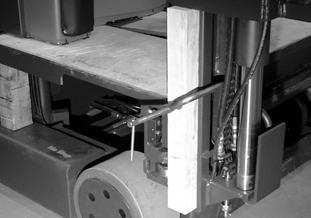
6.Elevate the load handler approx. 12 in. (300 mm). Block and clamp a wooden block in the mini-mast channel. See Figure7-76 .
7.Lower the load handler onto the blocks. Let lift chain, hoses, and cable go slack.
8.Turn the key switch OFF and disconnect the battery connector.
9.Remove the power supply cable harness from connector JP5 under the turret. Remove cable ties on the cable harness, noting their location for reinstallation. Using the appropriate tool, remove the pins from the J5 connector. Attach a 6 ft. (2 m) length of 18 gauge wire to these pins and tape them together securely to aid in routing the new harness cable. Secure the other end of the wire to the turret.
Publication: 1089040, Issued: 08 Apr 2016 7-59
Section 7.Component Procedures
Model 9600/9700 Swing-Reach ® Lift Truck
Mini-Mast Height Proximity SensorElectrical Components
10.Use cables ties to temporarily attach the over-the-mast electrical cable to one of the hydraulic hoses in the turret. This keeps tension on the electrical cable inside the load handler.
11.Remove the load handler pulley bracket cover. Remove the hoses and cable from the pulleys, laying them carefully to the side of the mini-mast.
12.Using a hoist or other suitable lifting device, support the load handler carriage with straps.

13.Remove the lift chain anchor at the bottom of the mini-mast by removing jam nut, hex nut, and cotter pin. Lift the chain over the pulley and lay it carefully over the actuator. To pass the chain anchor through the pulley, twist the lift cylinder 90° with a large screwdriver in the pulley eye. Then twist the cylinder back into its normal position. See Figure7-77.
16.Using the hoist, slowly and carefully lift the load handler up the mini-mast to within 12 in. (300 mm) of the top plate. Make sure cable, hoses, and chain do not bind or catch on the load handler.
17.Working from a work platform or ladder, remove the stop plate on the top of the mini-mast. Cut the cable ties securing sensor to hydraulic tubing, noting their location for later installation.
18.Using the hoist, continue lifting the load handler past the cylin der until the sensor is visible above the mini-mast.
19.Working from a work platform or ladder, remove the three bolts holding the sensor bracket to the mini-mast. Pull the wiring harness through the metal tubing until the attached wire appears. Remove wire and tape it to the replacement sensor assembly cable.
14.Remove the pulley bracket assembly from the mini-mast cylinder by removing the mounting bolt in the end of the cylinder.

15.Loosen mini-mast puck adjuster lock nuts and back out the adjusting screws completely. See Figure7-78
Publication: 1089040, Issued: 08 Apr 2016
Model 9600/9700 Swing-Reach ® Lift Truck
Section 7.Component Procedures
Electrical Components Mini-Mast Height Proximity Sensor
Installation [84 in./213 cm mini-mast]
1.Check the height sensor assembly as noted in “Checking the Height Sensor Assembly” on page7-62
2.Working from a work platform or ladder, attach the new height sensor to the load handler. Pull the wire and harness through the metal tubing. Connect the sensor harness to the height manager card at connector JP2. Attach cable ties in their original locations on the tubing and in the turret.
3.Make sure the mini-mast cylinder puck adjuster lock nuts are loosened and the adjuster screws backed out completely.

20.Remove the fender washer securing the sensor housing in the mounting bracket. Remove the sensor housing and wave spring. Remove the sensor from the housing. See Figure7-80 and Figure7-81 on page7-62 .
4.Insert a section of 1.5 in. (38 mm) wide strap steel at least 12 in. (30.5 cm) down the mini-mast to act as a “shoehorn” to guide the sensor past the cutout in the rail and the traverse position feedback pot. Remove the strap steel when the sensor has engaged the rail.
Failure to guide the sensor results in damage to sensor and feedback pot.
5.Using the hoist, slowly lower the load handler until it rests on the blocks. Make sure cable, hoses, and chain do not bind or catch on the load handler.
6.Apply thread-locking compound (P/N1013829) to the mini-mast stop plate mounting screws and install the stop plate. Torque to 70 ft. lb. (95 Nm).
NOTE: You should take advantage of the opportunity to inspect the mini-mast cylinder pucks. Replace as required. See “Mini-Mast Pucks” on page7-112.
21.Inspect load handler bearings.
22.Clean the mini-mast cylinder. Apply a clean coating of grease where the pucks contact the cylinder.

7.Apply thread-locking compound (P/N1013829) to the pulley bracket assembly mounting bolt and install the bracket assembly on the end of the mini-mast cylinder. Torque to 90 ft. lb. (122 Nm).
8.Using a large screwdriver, twist the mini-mast cylinder 90° and feed the mini-mast lift chain anchor through the lift chain pulley. Once the chain hangs freely, twist the cylinde r back to its normal
Publication: 1089040, Issued: 08 Apr 2016 7-61


