1 minute read
Model 9600/9700 Swing-Reach ® Lift Truck
Section 7.Component Procedures
Electrical Components Wiring and Harness Connectors
Testing
Do not pierce wire insulation with a sharp point while troubleshooting.
The wedge lock has slotted openings in the forward (mating) end. These slots accommodate circuit test tabs that are approx. 3.3 by 0.6 mm, that prevent damage to the receptacle. For circuit testing in the field, use a flat probe such as a pocket knife blade. Do not use a probe with a sharp point.
Publication: 1089040, Issued: 08 Apr 2016
Section 7.Component Procedures
Model 9600/9700 Swing-Reach ® Lift Truck
Power CablesElectrical Components
Power Cables
Check power cables for:
•evidence of overheating
•burned spots in the cable
•nicks in the insulation
•damaged or overheated terminal lugs
•damaged mounting hardware or brackets
•damaged traction motor insulation within the bracket located at the top of the traction motor (sleeve material should be installed to protect traction motor cables at this location)
Replace damaged cables or mounting hardware as necessary.
Power cables are marked on the terminal lug with the location where they belong. If the marking is missing or is not readable, remark the cable with the correct information.
NOTE: Terminal lugs may be replaced in the field using the appropriate crimping tools. Crimping tool, lugs, and heatshrink are available through the Parts Distribution Center. Failure to use correct cables, terminal hardware, and torque values can result in overheating and damage to components.
Power Cable Repair
Traditional lug crimping techniques for power cables on DC motors may not meet the higher current requirements of AC motors. Use Manual Crimp Tool (P/N 1069861) when crimping power cables for all AC motors. This tool may also be used to repair power cables for DC motors.
1.Remove the bad cable(s).
2.Using the removed cable(s) for reference, cut an appropriate amount of replacement cable of the same gauge.
3.Set the adjustment screw on the manual crimp tool head to match the cable gauge.
7-50
4.Strip the cable jacket to fit the terminal to be crimped. Refer to Table7-3 and Table7-4.
Table 7-3.Cable Jacket Strip Length - Short Barrels
AWG Lug P/N Strip Length
1/01002215/001-00411/16 in. (17 mm)
2/01002215/005-00813/16 in. (21 mm)
3/01002215/009-0121 in. (25mm)
4/01002215/013-0151-1/16 in. (27 mm)
Table 7-4.Cable Jacket Strip Length - Long Barrels
AWG Lug P/N Strip Length
1/01002217/001-003
2/01002217/004-006
3/01002217/007-009
1-9/16 in. (40 mm)
4/01002217/010-0111-11/16 in. (43 mm)
5.Insert cable into terminal.
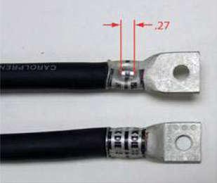
6.Place cable and terminal into tool die and crimp. Refer to pictures below for what completed crimps should look like.

Figure 7-64.Short Barrel Terminal
Publication: 1089040, Issued: 08 Apr 2016


