6 minute read
Attachments


General Instructions
Use only approved attachments. Mustang Manufacturing cannot be responsible if the machine is used with non-approved attachments. Read the operator’s manual provided with all attachments used with the machine before starting the engine. A loaded attachment changes the center-of-gravits of the machine. Use caution! Never exceed the rated capacity (See “Weights (Equipped w/ 2-Post ROPS)” on page30). Before using an attachment, check that the attachment is undamaged and properly connected and locked.
WARNING WARNING WARNING
Practice using an attachment before working with it.
Connecting Attachments
Check that hitch pins and auxiliary hydraulic connections are properly connected and locked.
Standard All-Tach® Hitch Connection
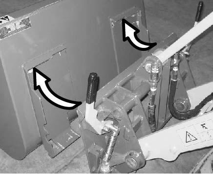
1.Position the attachment so the attachment flange fits over the top lip of the hitch (Figure 52).
2.Pull the joystick rearward until the attachment is flush against the hitch surface.
3.Perform “Mandatory Safety Shutdown Procedure” on page8.
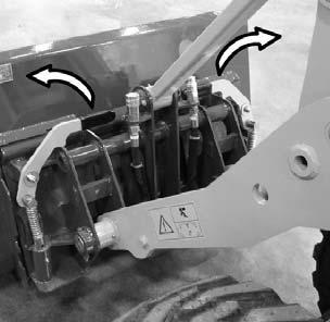
4.Push the locking handles (1, Figure 53) inward and downward until the attachment is locked onto the hitch as shown.
5.Check that the attachment is securely locked onto the hitch: the lip on the attachment is completely engaged over the top of the hitch, and the locking pins on the bottom of the hitch are fully engaged down into the attachment.
Warning
Check that attachments are securely fastened to the hitch before working. Serious injury or death could result.
6.Perform “Engine Start” on page49.
Hydraulic Power-A-Tach ® Hitch Connection
Caution
The hydraulic Power-A-Tach® hitch lock switch activates the auxiliary hydraulic circuit. Connect the auxiliary hydraulic connections (see “Auxiliary Hydraulics” on page63) to the attachment after connecting the attachment to the Power-A-Tach® hitch.
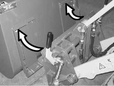
1.Position the attachment so the attachment flange fits over the top lip of the hitch (Figure 54).
2.Pull the joystick rearward until the attachment is flush against the hitch surface.
3.Push the Power-A-Tach® hitch lock switch (1, Figure 55) to lock the attachment onto the hitch as shown in Figure 55
4.Make sure the attachment is securely locked on the hitch: the locking handles (1, Figure 53) must be horizontal, with the lip on the attachment completely engaged over the top of the hitch, and the hitch pins on the bottom of the hitch fully engaged down into the attachment.
Disconnecting Attachments
Standard All-Tach® Hitch Disconnection
1.Lower the attachment to the ground. See “Multi-purpose Joystick” on page57.
2.Turn off the engine. Move the multi-purpose joystick several times in all directions to depressurize the hydraulic system.
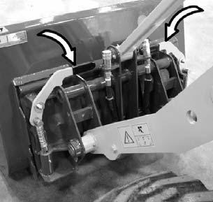
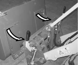
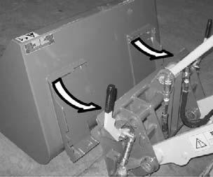
3.Pull the locking handles upward until the pins disengage from the attachment (Figure 56).
4.Perform “Engine Start” on page49.
5.Tilt the hitch forward (see “Multi-purpose Joystick” on page57) and back away from the attachment (Figure 57).
Hydraulic Power-A-Tach ® Hitch Disconnection
Caution
Disconnect the auxiliary hydraulic connections (see “Auxiliary Hydraulics” on page63) before disconnecting the attachment from the Power-A-Tach® hitch.
1.Lower the attachment to the ground. See “Multi-purpose Joystick” on page57.
2.Press the Power-A-Tach® hitch unlock switch (1, Figure 58) to unlock the attachment on the hitch as shown in Figure 58.
3.Tilt the hitch forward (see “Multi-purpose Joystick” on page57) and back away from the attachment (Figure 59).
Auxiliary Hydraulics
Auxiliary hydraulics are used for hydraulic-powered attachments.
Important: Be sure the auxiliary hydraulics control lever is in the centered/neutral position when starting the engine.
Auxiliary Hydraulics Connections
Important: Be sure that the hydraulic connections are clean. Hydraulic oil contamination can damage the hydraulic system.
1.Perform the “Mandatory Safety Shutdown Procedure” on page8.
Caution
If a Power-A-Tach® htich is installed, connect the auxiliary hydraulic connections to the attachment after connecting the attachment to the Power-A-Tach® hitch. Disconnect the auxiliary hydraulic connections before disconnecting the attachment from the Power-A-Tach® hitch.
2.Place the auxiliary hydraulics control lever into “float” position (see Figure “Auxiliary Hydraulics Control Lever” on page64).
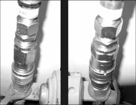
3. To connect: press the hose connections firmly down into the auxiliary hydraulic connections until they snap in place.
To disconnect: push down on the locking ring (1, Figure 60) until the hose connections release.
4.Return the auxiliary hydraulics control lever into the neutral position.
Auxiliary Hydraulics Control Lever
1. Neutral (1, Figure 61): The centered position is neutral. The auxiliary hydraulics control lever is springloaded to return to this position.
2.Float (2): The float position returns all hydraulic flow in the auxiliary circuit to tank. This position is inward past the detent.
3. Flow Activation (3A, 3B): Pushing the auxiliary hydraulics control lever out activates the auxiliary hydraulic flow in one direction. Pulling the lever in reverses flow direction.
4. Power Detent (4): Pulling the lever all the way in past the detent activates continuous auxiliary hydraulic flow.
1. Neutral position
2. Float positions
3. Flow activation position
4. Power detent
Important: To prevent over-heating, move the auxiliary hydraulics control lever to the neutral position when auxiliary hydraulics are not in use.

Operating Attachments
Use only approved attachments. Mustang Manufacturing cannot be responsible for safety if the unit is used with non-approved attachments.
Warning
Some general guidelines for attachments are included in this section. These guidelines are not a replacement for the attachment manufacturer’s operating instructions.
Before installing, operating and servicing attachments, carefully read the manufacturer’s operating instructions. Contact the responsible representative for more information.
Contact a Mustang dealer for more information about approved attachments. Observe maximum load capacities. See “Specifications” on page27.
Bucket
See “Load Handling” on page56 for driving with a load. See “Dimensions” on page29 and “Dimensions” on page29 for bucket dimensions.
Note: When loading the bucket, use the position mark on the bucket to determine the tipping position.
Loading Loose Material
1.Lower the bucket and adjust the edge parallel to the ground.
2.Drive toward the material to be loaded. Determine the correct driving speed according to the type of material and working conditions.
3.Lift the load arm slightly (“inching”) to load the front axle, and to avoid slipping.
Note: If loading material that the bucket has difficulties penetrating, use the joystick to lift and lower the bucket.
4.Retract the bucket when it is full.
5.Move the bucket into transport position.
Loading Soft Material
1.Lower the bucket onto the material
2.Extend the bucket to the desired digging angle.
3.Drive forward so that the edge of the bucket penetrates the material.
4.Reduce the tipping angle to cut an even layer of material and to avoid slipping.
Loading Hard Material
1.Lower the bucket onto the material.
2.Extend the bucket to the desired digging angle.
3.Drive forward, press the bucket slightly downward so that the bucket penetrates the material.
Note: Avoid extreme tire slipping.
4.Reduce the tipping angle.
5.While driving forward, operate the joystick to lower and lift the bucket, and to constantly load the front axle.
Towing and Retrieval
Do not use the loader for towing (other vehicles, trailers, equipment, etc.).
Important: The machine cannot be tow-started because there is no direct mechanical connection between the wheels and engine. Attempting to tow-start the machine may damage the drive system.
Precautions
Only tow the loader if the steering and brakes are functional, if it cannot be repaired on-site, and if it cannot be transported using any other method. Only tow the loader until it is moved to a location where it can be safely repaired.
Important: If moving the loader more than a few hundred meters, use a flatbed truck or similar vehicle to transport the loader, to prevent overheating the hydraulic system. See “Loading and Transporting” on page69.
Preparation
1.Perform the “Mandatory Safety Shutdown Procedure” on page8.
2.Tilt up the operator’s platform. See “Tilting the Platform Up” on page77.
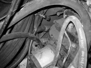
3.Loosen the bypass valve bolts (1, Figure 62) 3 revolutions.
Caution
Do not loosen the bypass valve bolts more than 3 revolutions. The bypass valve bolts can come out of the pump, resulting in a rapid loss of hydraulic fluid.
4.Tilt and secure the operator’s platform back into the operating position. See “Tilting the Platform Down” on page79.
Towing Procedure
1.Attach the tow bar/cable to the front frame tie-down points or the tow hitch (Figure 63) located at the rear of the loader. .
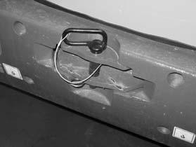
Important: Only use a tow bar or tow cable of sufficient capacity.
2.Tow the unit slowly and with caution. Do not tow continuously for longer than three minutes at a time.
Important: Use the tow hitch to tow the machine with another vehicle ONLY. Do not tow loads or other vehicles with the machine.
Caution
Do not allow anyone near the tow bar or tow cable while the loader is being towed. Do not allow the tow bar or tow cable to become damaged; the fracture load must be at least three times as great as the towing vehicle’s pulling power. Do not exceed 5 km/h (3 mph) while towing, or damage to the hydraulic system could occur.
After Towing
1.Tilt up the operator’s platform. See “Tilting the Platform Up” on page77.
2.Tighten the bypass valve bolts to 70 Nm (52 lbf-ft).
Note: Do not over-torque this screw.
3.Tilt and secure the operator’s platform back into the operating position. See “Tilting the Platform Down” on page79.
4.Secure the loader against rolling away and unauthorized use.


