
10 minute read
Instrument Panel and Indicators


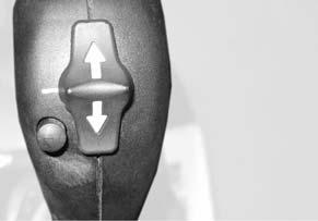
1Forward travelDrive direction thumb switch on joystick is in forward position (page50).
2Pre-heatIlluminates when the ignition key is in the “I” (Run) position, goes out when the glow plugs have heated sufficiently to start the engine (page50).
3Engine oil temperature warning
4Hydraulic oil filter
See page42.
See page42.
5Differential lockDifferential lock engaged (page55).
6Right turn/ hazard lights Right turn signal engaged (page53). Hazard lights (page36).
7Parking brakeParking brake engaged (page49).
8Road lightsRoad lights upper beam engaged (page36, page44).
9Rearward travelDrive direction thumb switch on joystick is in Reverse position (page49).
10AlternatorAlternator not charging.
11Slow speedLow speed drive engaged, (See item 22 on page36).
12Left turn/ hazard lights Left turn signal engaged (page53). Hazard lights (page36).
13Fuel levelDisplays the amount of fuel in the tank.
14Fast speedHigh speed drive engaged (See item 22 on page36).
15Hydraulic oil temperature See page42.
16Engine oil pressure Engine oil pressure too low.
17Hour meterDisplays hours of operation.
18Low fuelFuel level too low.
19Engine rpmDisplays engine rpm.
20Volt meterDisplays system voltage level. Start-up - 3 bars illuminate, if battery is fully charged. During operation - 4-5 bars illuminate. Alternator overheat - 6 bars illuminate, see page42.
21Engine oil temperature Displays temperature level.
Cab Controls (Cab only)
Cab Environment Controls
To operate the cab heater and air circulation fan:
1.Move lever (1, Figure 22) down to increase heat; up to reduce heat.
2.Turn the fan control (2, Figure 22) clockwise to increase circulation fan speed; counter-clockwise to decrease circulation fan speed.
Cab Windshield Wiper Controls
Press the icon side of the wiper switches to the first detent to activate the wiper blades. Press the icon side of the switches past the detent to activate the washer fluid.
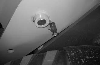
Cab Dome Light
The dome light is located on the cab ceiling. Push button (1, Figure 24) to turn the light on/off.
Cab Defrost
Turn the vents (1, Figure 25), located on the left and right side of the cab, toward the window to defrost the window.
Warning Indicators
Important: If any of the following indicators illuminate when the engine is running, turn off the engine immediately. Correct the problem before re-starting the engine. During normal operation these indicators should be OFF.
Figure26 – Warning Indicators
No.IndicatorDescription
1Engine coolant temperature warning
Temperature is too hot.
2Volt meterAlternator overheat - 6 bars illuminate.
3Engine oil pressure Pressure is too low.
4Hydraulic oil temperature
5Hydraulic oil filter
Temperature is too hot.
Hydraulic oil filter service required.
Operator’s Seat Adjustment
Warning
Never adjust the operator’s seat when the engine is running.
Adjust the operator’s seat so all controls are easy to reach and the pedals can be completely depressed with your back against the seat.
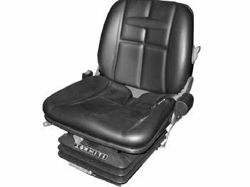
1. Forward/rearward adjustment: Pull the lever up, adjust the seat and release the lever. Check that the seat is locked in place.
2.Weight adjustment: While sitting in the seat, rotate the knob until the desired tension is reached.
3.Recline adjustment: Pull the front lever up, recline the seat back as desired and release the lever. Check that the seat is locked in place.
4.Height adjustment: Rotate knob until the desired seat height is reached.
Seat Belt
Figure27 – Operator’s Seat Adjustment
Always fasten the seat belt securely and properly. Never operate the machine without the seat belt fastened around the operator.
Important: Inspect the seat belt for damage before use. Replace if damaged. Keep the seat belt (5, Figure 27) clean. Use only soap and water to wash seat belt. Cleaning solvents can damage seat belt.
Ignition Key Switch
“0” position: All power off. Key can be inserted/removed.
“I” position: Run position.
“II” position: Start position. Holding the switch in this position starts the engine. See “Engine Start” on page49.
Note: Switch must be returned to “0” position between starting attempts to reset the start safety interlock.
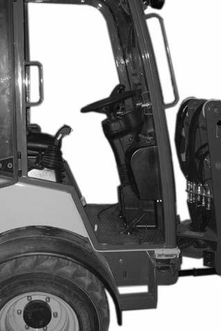
Steering Column Adjustment
Warning
Never adjust the steering column when the engine is running.
Adjust the steering column for visibility, usability and comfort.
1.Push the adjustment lever (1, Figure 29) downward.
2.Adjust the steering column to the desired position.
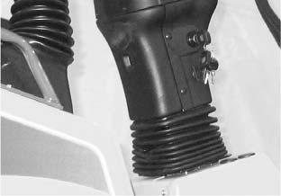
3.Release the adjustment lever.
4.Check that the steering column is locked in place.
Control Lever
The control lever on the steering column controls the following functions:
1.Push the control lever in to activate the horn (1, Figure 30).

2.Twist the end of the control lever to activate the position lights (2).
3.Push the control lever forward or rearward to activate the turn signals (3).
4.Push the control lever downward to activate “high” beam (driving light).
5.Pull the control lever upward to activate “low” beam (dippedbeam light).
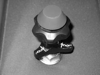
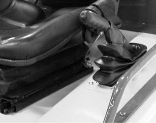
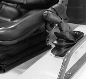
Hand Throttle
The hand throttle, located to the right of the operator’s seat, controls engine speed independently from the accelerator pedal. The hand throttle does not control travel speed.
1.Loosen the throttle lock ring (1, Figure 32).
2.Press the red throttle release button (2).
3.Pull/push the throttle control knob (3) and the throttle release button as a unit.
Note: The throttle can be quickly placed into the idle position by firmly pushing against the throttle release button. For normal operation, move the throttle release button (1) and the throttle control knob (3) as a unit to prevent undue wear on the throttle mechanism.
4.For fine adjustments, rotate the throttle control knob (3).
1. “High” beam (driving light)
2. “Low” beam (dipped-beam light)
3. Marker/turn signal
5.Tighten the throttle lock ring (1) to lock the throttle in position.
12V Accessory Power Outlet
Use the 12V accessory power outlet (1, Figure 33), on the steering column. See “Fuse Panel - Steering Column” on page99 for fuse and amperage information.
Operation
Pre-Operation Checklist
Check the following before starting the machine (for all fluid level checks, fill if required):
•Fuel, hydraulic, radiator, and engine oil caps for tightness.
•Fluid leaks: fuel, hydraulic oil, engine oil, coolant, etc.
•Radiator coolant level. See “Fluid Capacities/Lubricants” on page27 for proper mixture.
•Engine coolant level and system for leaks.
•Hydraulic system for leaks.
•Fuel level. See “Fuel System” on page86.
•Engine oil level. See “Engine Oil Level Check” on page80.
•Hydraulic fluid level. See “Checking Hydraulic Oil Level” on page88.
•Engine cover latch securely fastened.
•Clean engine area of flammable materials.
•Engine fan and accessory belts.
•Air cleaner (air filter restriction indicator). See “Air Cleaner” on page82.
•Hydraulic hose condition.
•Brake fluid level.
•Tire condition and pressure.
•Condition of any attachments to be used.
•Lift arm and cylinder condition (look for bends/cracks/etc.).
•Frame condition (look for bends/cracks/etc.).
•Overhead cab, frame, or bar (Rollover Protective Structure [ROPS]).
•Overhead guard attachment (Falling Object Protective Structure [FOPS]).
•Finger guards.
•Safety decals (replace as required).
•Safety warnings (securely attached and readable).
•Seat belt (check for proper function/binding) and mounting hardware.
•Horn and lights.
•Intake hoses.
•Pivot points for proper operation.
•Broken and/or loose parts (repair as required).
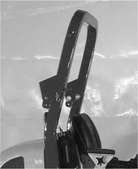
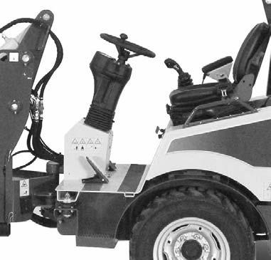
Extend the ROPS
If the machine is equipped with a folding ROPS, never operate the machine without the ROPS fully raised (Figure 34). Only fold the ROPS temporarily if necessary during transport.
Secure the ROPS into the transport position:
1.Remove the cotter pins (both sides) (1, Figure 34).
2.Remove the clevis pins (both sides) (2, Figure 34).
3.Fold the ROPS rearward.
Do not allow the ROPS to fall rearward, or damage to the engine cover or injury to nearby persons may occur. Stay clear from underneath the ROPS as it is folded.
4.Insert the clevis pins (both sides) into transport lock position (2, Figure 35).
5.Insert the cotter pins (both sides) to secure the clevis pins (both sides). Restore the ROPS to the raised position:
1.Remove the cotter pins (both sides) from the clevis pins (both sides).
2.Remove the clevis pins (both sides) (2, Figure 35).
3.Fold the ROPS upward and forward.
4.Insert the clevis pins (both sides) (2, Figure 34).
5.Insert the cotter pins (both sides) (1, Figure 34).
Entering and Exiting Maintain three-point contact and face the machine at all times when entering and exiting. Do not use the steering wheel for entry or exit. Never jump from the machine. Never enter or exit a moving machine. Failure to maintain three-point contact may result in injury.
Engine Start
Important: The machine cannot be tow-started because there is no direct mechanical connection between the wheels and engine. Attempting to tow-start the machine can damage the drive system.
Warning
Always fasten the seat belt before operating the machine. Repair or replace any damaged seat belt and lock parts before operation.
Important: Do not use starting fluid (ether) with preheat systems. An explosion can result, which can cause engine damage.
1.Adjust the operator’s seat (see “Operator’s Seat Adjustment” on page43) and fasten the seat belt.
2.Adjust the steering column (see “Steering Column Adjustment” on page44).

3.Engage the parking brake (1, Figure 38), lift the lever (2) into the upright position as shown.
Note: When the parking brake is engaged, travel drive is disconnected.
4.Check that the battery disconnect switch (1, Figure 39) is switched on. To connect battery and enable all electrical functions, rotate key (1) clockwise to the notched position (2). To disconnect battery and lock out all electrical functions, turn key (1) counter-clockwise to position (2).
Note: On earlier machines, key (1) can be removed from the battery disconnect switch.
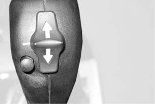
5.Place forward/reverse drive switch (Figure 40) on the top of the joystick into the neutral position.

6.Place auxiliary hydraulics control lever into neutral (center) position (1, Figure 41).
Important: The engine will not start if the auxilary hydraulics control lever is not in the neutral position.
7.Turn the ignition key to the “I” (Run) position (Figure 42).
8.When the pre-heat indicator light (3, Figure 42) goes off, turn the ignition key to the “II” (Start) position. Release the key when the engine starts.
9.If the engine does not start after 15 seconds, turn the key back to the “0” (off) position, wait one minute and repeat steps 7-8. If the engine does not start after several attempts, see “Troubleshooting” on page109.
Note: Switch must be returned to “0” position between starting attempts to reset the start safety interlock.
10.Immediately after starting the engine, all warning indicator lights should go off (see “Warning Indicators” on page42).
11.Proceed to “Warm-up” on page51.
Engine Shut Down
1.Perform the “Mandatory Safety Shutdown Procedure” on page8.
2.Perform a visual inspection:
•Hydraulic system leaks?
•Coolant system leaks?
•Fuel system leaks?
•Damage to machine (tires, attachment hitch, attachment, etc.)?
3.Completely fill the fuel tank.
Warm-up
Important: Do not run a cold engine under load; engine life may be shortened.
1.Run the engine at a low, consistent speed for a few minutes before operating any controls. Check for any unusual sounds and vibrations.
2.Check if any indicators illuminate (see “Warning Indicators” on page42).
Important: If unusual sounds or vibrations occur, or if any warning indicators illuminate, stop the engine immediately and determine the cause. Repair or replace parts as necessary before re-starting the engine.
3.Exhaust gas color should be light blue or colorless.
Note: Black exhaust indicates possible engine malfunction. See “Engine” on page109.
Important: Do not run a malfunctioning engine under load; engine life may be shortened.
4.During warm-up, test the following for proper function:
•Brake/Inch pedal. See “Controls and Switches” on page36. See “Travel” on page53.
•Steering. See “Controls and Switches” on page36.
•Accelerator pedal. See “Controls and Switches” on page36.
•Multi-purpose joystick. See “Multi-purpose Joystick” on page57.
•Forward/reverse drive switch on multi-purpose joystick. See “Travel” on page53.
New Machines
1.After starting the engine for the first time, let the engine idle for 15 minutes.
2.After 15 minutes, perform the “Mandatory Safety Shutdown Procedure” on page8.
3.Check for proper engine oil pressure, engine oil level, diesel fuel leaks, engine oil leaks, coolant leaks, and indicator/gauge operation.
4.During the first hour of operation, vary the engine speed and the load, with short periods of maximum load and engine speed operation.
5.During the first four to five hours of operation, avoid long periods of minimum or maximum load and engine speed operation.
6.During the first 50 hours of operation, check the engine oil pressure, engine temperature frequently.
7.After the first 50 hours of operation, replace engine oil and engine oil filter and check and adjust cooling fan v-belt. See “Changing Engine Oil and Filter” on page80. See “Checking and Adjusting V-belt Tension” on page88.
8.Check the engine oil and coolant levels frequently and refill as necessary. See “Engine Oil Level Check” on page80 and “Checking Coolant Level” on page84.
Driving on Public Roads
Follow the applicable legal regulations of the country where the loader is being used. Regulations are specified in the operation license or in the vehicle papers.
Important: Only the attachments listed in the operation license or vehicle papers are admissible for driving on public roads.
1.Follow mandatory accident prevention regulations. Complete a functional check of:
•Brakes
•Steering
•Lights
2.Empty the bucket (if applicable).
3.Completely lower the lift arm and tilt the attachment/hitch back as far as it will go.
4.Engage multi-purpose joystick control safety lock. See “Multi-purpose Joystick” on page57.
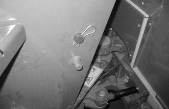
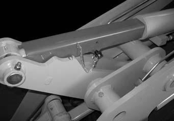
5.AL400 Series machines: a.Remove the lock pin (1, Figure 43), and pull the lock bar (2) from the machine. b.Slide the lock bar (2) all the way through the locking holes (3) in the lift arm and machine. c.Replace the lock pin (1) into the lock bar.
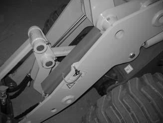
6.AL500 Series machines: a.Remove the quick-release pin (1, Figure 44), and lift the cylinder stop channel (2) off the machine. b.Place the cylinder stop channel (2) over the tilt cylinder (3) to brace the tilt cylinder in the fully extended postion. c.Replace the quick-release (1) into the cylinder stop channel so it passes under the tilt cylinder rod.
Travel
Do not move the drive direction switch (Figure 46) while traveling. The machine may react suddenly, causing an accident. Change drive direction only when stopped. Use the directional indicators when changing travel direction. See “Controls and Switches” on page36.
Warning
Important: If the optional backup alarm is installed, and the parking brake is released, the backup alarm activates when the drive direction switch is in reverse.
1.Be sure that the area around the loader is clear of bystanders and obstacles.
2.Using the multi-purpose joystick, lift the lift arm/attachment. Keep the attachment as near to the ground as possible for good stability and visibility. See “Load Handling” on page56.
3.Release the parking brake. Press the button (1, Figure 45) and press the lever (2) downward. Release the button.
Note: When the parking brake is engaged, travel drive is disabled.
4.Use the drive direction switch to change the loader drive direction.
Note: The drive direction indicator should illuminate when the drive direction switch is in forward or rearward position.
Drive direction switch position
Forward Indicator light for forward drive lights; loader drive is in forward.
MiddleLoader drive is in neutral.
Rearward Indicator light for reverse drive lights; loader drive is in reverse.
5.Select either the high or low drive speed using the slow/fast speed switch (21, Figure 46) according to the job and work site conditions.
6.Slowly press the accelerator pedal. Driving speed is proportional to the accelerator’s displacement.
Caution
Travel cautiously, under complete control at all times. Avoid sudden directional changes while traveling.
Important: Use the accelerator pedal to control travel speed. Use the hand throttle to control engine speed. See “Hand Throttle” on page45.
7.Use the brake/inch pedal to regulate gradual travel speeds and braking.
Note: Do not use the brake/inch pedal as a footrest.


