10 minute read
Engine Maintenance


Allow engine and hydraulic system components to cool before maintenance.
Engine Oil
Engine Oil Level Check
1.Position the machine on a level surface.
2.Perform the “Mandatory Safety Shutdown Procedure” on page8.
3.Wait until the machine has cooled down. See “Service Safety Practices” on page12.
4.Open engine cover.
5.Remove the dipstick (1, Figure 76). Wipe dipstick with a clean cloth.
6.Insert the dipstick until it is fully inserted, and remove.
7.Read markings on the dipstick, markings represent FULL and LOW (add oil) levels.
See “Maintenance Schedule” on page74 for the service interval for replacing the engine oil and filter.
Changing Engine Oil and Filter
Change the engine oil and filter after the first 50 hours of use; every 250 hours thereafter.
1.Position the machine on a level surface.
2.Perform the “Mandatory Safety Shutdown Procedure” on page8.
3.Wait until the machine has cooled down. See “Service Safety Practices” on page12.
4.Remove the engine access panel (1, Figure 77).
Notice: Removing engine access panel requires two people.
5.Position a waste oil collection container to catch draining oil (2, Figure 78).
Important: Dispose of waste engine oil according to environmental laws or take to a recycling center for proper disposal. DO NOT pour waste engine oil onto the ground or down a drain.
1
6.Remove the drain plug (1, Figure 79) from the oil pan and allow the oil to drain into the waste oil collection container.
7.Remove the oil filter, using a filter wrench as necessary.
8.Put clean oil on the new oil filter gasket. Install the filter and tighten 3/4 turn past the point where the gasket contacts the filter head.
9.Reinstall and tighten the drain plug.
10.Reinstall the engine access panel (1, Figure 77).
Notice: Reinstalling engine access panel requires two people.
11.Remove the oil fill cap (2, Figure 76) and add the recommended oil. See “Fluid Capacities/Lubricants” on page27.
12.Start the engine and let it run for several minutes at low idle. Stop the engine. Wait until the machine has cooled down. See “Service Safety Practices” on page12.
13.Check for leaks at the oil filter and drain plug. Check the oil level. If necessary, add oil until the oil level is at the FULL mark on the dipstick.
Air Cleaner
Important: Do not operate the engine without the air cleaner components installed or damage to the engine could occur. Failure to follow air cleaner servicing instructions can cause engine damage.
The air cleaner consists of an outer (primary) filter element, an inner (secondary) filter element, an air filter restriction indicator and a dust valve. If the air cleaner becomes restricted, the air filter restriction indicator (1, Figure 80) turns red to warn the operator that the element(s) require service. Push the reset button located on the end of the indicator after installing a clean filter element(s). Pinching the dust valve (2, Figure 80) opens a slit at the end of the valve, allowing accumulated dust in the end of the element cover to drop out without removing the cover.
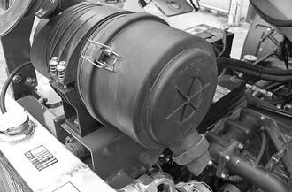
Only replace the inner element every third time the outer element is replaced, unless the outer element is damaged or the inner element is dirty.
Be sure that the restriction indicator, air cleaner intake hose, clamps and mounting bracket hardware are properly tightened.
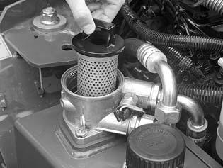
Accessing the Outer and Inner Filter Elements
1.Perform the “Mandatory Safety Shutdown Procedure” on page8.
2.Open the engine cover.
3.Unlatch the clamps on the air cleaner housing and remove the element cover.
4.Clean any debris from the cover.
Changing the Outer Filter Element
1.Perform the “Mandatory Safety Shutdown Procedure” on page8.
2.Carefully remove the outer filter element. Do not remove the inner filter element unless it is to be replaced. See “Changing the Inner Filter Element” on page83.
Note: Mustang does not recommend cleaning the outer filter element.
3.Clean any debris from the housing. Leave the inner filter element installed during this step to prevent debris from entering the engine intake manifold.
4.Install the new outer filter element.
Changing the Inner Filter Element
1.Complete all steps in “Accessing the Outer and Inner Filter Elements” on page83.
2.Remove the outer filter element.
3.Before removing the inner filter element from the housing, clean away any dirt built up in the housing. Leave the inner filter element installed during this step to prevent debris from entering the engine intake manifold.
4.Remove the inner filter element.
5.Check the inside of the housing for any damage that may interfere with the elements.
6.Be sure that the element sealing surfaces are clean.
7.Install the new inner filter element.
8.Reinstall/replace the outer filter element.
9.Latch the clamps to secure the element cover.
10.Check the hose connections and be sure they are all clamped and tightened properly.
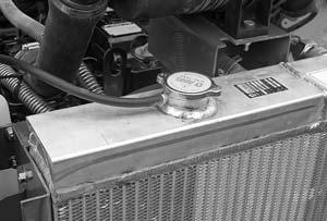
Engine Cooling System Checking Coolant Level
1.Perform the “Mandatory Safety Shutdown Procedure” on page8.
2.Open the engine cover (2, Figure 81). Check the coolant level in the expansion reservoir (1, Figure 81). The expansion reservoir must be 1/3 to 1/2 full for a cold engine and 2/3 to 3/4 full for a hot engine.
Warning
Do not remove the radiator cap when the coolant is hot. Serious burns may occur.
3.Slowly loosen the radiator cap and allow pressure to escape.
4.Remove the cap and add coolant as necessary. See “Fluid Capacities/Lubricants” on page27 for coolant specification.
5.Reinstall the cap.
Cleaning Cooling System
1.Perform the “Mandatory Safety Shutdown Procedure” on page8.
2.Allow engine to cool.
3.Open engine cover.
4.Clean radiator and oil cooler by blowing air or high pressure water through the fins.
Important: High pressure may bend radiator fins; proceed with caution. Blow air in opposite direction of cooling fan to dislodge debris.
Draining/Refilling Cooling System
1.Perform the “Mandatory Safety Shutdown Procedure” on page8.
2.Allow engine to cool.
3.Open engine cover.
Do not remove radiator cap when the coolant is hot. Serious burns may occur.
4.Slowly loosen radiator cap (1, Figure 82) and allow pressure to escape. Remove cap.
5.Remove the engine access panel. See “Changing Engine Oil and Filter” on page80, step 4.
6.Position a suitable collection container underneath the radiator.
7.Open radiator drain valve (1, Figure 83). Drain valve is located at bottom of radiator, above frame member. Drain valve opening faces the front of the machine.
8.Position a collection container, capacity 8liters (2gallons), underneath the radiator drain.
Important: Drain the coolant into the container. Always dispose of coolant according to environmental laws. DO NOT pour onto the ground or down a drain.
9.Close radiator drain valve.
10.Completely fill the radiator with premixed coolant. See “Fluid Capacities/Lubricants” on page27 for coolant specification.
11.Reinstall radiator cap.
12.Complete all steps in “Checking Coolant Level” on page84.
13.Run the engine until it is at operating temperature.
14.Perform the “Mandatory Safety Shutdown Procedure” on page8.
15.Allow the engine to cool.
16.Open the engine cover.
17.Check the coolant level in the expansion reservoir. The reservoir must be 1/3 to 1/2 full for a cold engine and 2/3 to 3/4 full for a hot engine.
Fuel System
Use only proper types and grades of diesel fuel (“Fluid Capacities/Lubricants” on page27).
Diesel fuel is flammable. Keep the machine away from open flames. Do not smoke when refueling or when working on the engine. Stop the engine before fueling. Failure to follow instructions can cause fire and result in injury or death.
Important: The fuel tank is filled at the factory with United States off-road grade diesel fuel, which is dyed red for identification. It may take several fillings of the fuel tank before the red dye is purged from the fuel system.
Adding Fuel
1.Perform the “Mandatory Safety Shutdown Procedure” on page8.
2.High-quality diesel fuel is required for correct engine performance. See “Fluid Capacities/Lubricants” on page27.
3.Remove fuel cap (1, Figure 84).
4.Add fuel into fuel filler neck (2).

5.Inspect the wire-mesh fuel strainer located in the filler neck and remove any accumulated residue that may be present. Replace the strainer if damaged.
Important: The engine requires low sulfur or ultra-low sulfur diesel fuel to maintain proper engine performance. Yanmar will allow up to a 5% (B5) mixture of BioDiesel. Also see “Fluid Capacities/Lubricants” on page27.
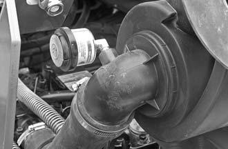
Changing Fuel Filter
The fuel filter (1, Figure 85) is located in the fuel line before the fuel pump. Access the fuel filter by opening the engine cover and tilting the loader platform. See “Tilting the Platform Up” on page77. Replace the fuel filter at regular intervals specified. See “Maintenance Schedule” on page74.
The fuel filter is located on the left side of the loader.
1.Perform the “Mandatory Safety Shutdown Procedure” on page8.
2.Shut off the fuel supply by turning the fuel shut-off valve on top of the water separator to OFF.
3.Shut off return line by turning valve on the fuel tank counter-clockwise.
4.Remove the fuel filter.
5.Lubricate new fuel filter gasket with diesel fuel.
6.Install and tighten the filter 3/4 turn past point the where the gasket contacts the filter head.
7.Turn shut-off valve on water separator to ON.
8.Open the fuel return line by turning the valve on the fuel tank clockwise. The engine is self-priming. To remove air before starting, turn the ignition key to the ON position for 30 seconds.
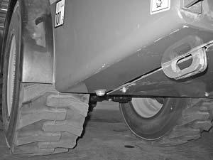
Servicing Water Separator
The water separator contains an indicator ring that will float on top of any accumulated water. Under normal conditions this ring sits at the bottom of the separator. If the ring is somewhere between the bottom and the white ring (2, Figure 86), then the accumulated water must be drained.
1.Perform the “Mandatory Safety Shutdown Procedure” on page8.
2.To view the water separator, use the slot in front of the right-rear tire, near the step.
3.Access the water separator underneath the loader, near the right-rear wheel. Check for water in water separator by checking level of float in water separator bowl. If water is present, complete steps 4-7.
4.Turn the fuel shut-off valve lever (1, Figure 86) on the water separator to the OFF position.
5.Place a container underneath the drain plug (3, Figure 86). Loosen the plug until water begins draining. Allow water to drain until the indicator ring returns to the bottom of the water separator.
6.Tighten the drain plug and discard fuel/water according to environmental laws. DO NOT pour the fuel/water onto the ground or down a drain.
7.Turn the fuel shut-off valve lever (1) on the water separator to the ON position.
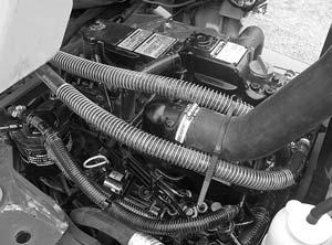
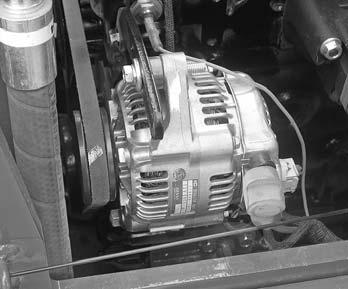
Checking and Adjusting V-belt Tension
1.Perform the “Mandatory Safety Shutdown Procedure” on page8.
2.Open the engine cover.
3.Inspect the V-belt (1, Figure 87) for damage. If damaged, have it replaced by your dealer.
4.Press on the V-belt (1) mid-way between pulleys to check deflection. The belt should deflect no more than 8 mm (5/16").
5.If deflection is more than 8 mm (5/16"): Loosen the adjustment bolt (2) and rotate the alternator (3) outward until V-belt tension is correct. Tighten bolt (2) and recheck V-belt tension.
Hydraulic System Maintenance
Warning
Never use your hands to search for hydraulic fluid leaks; use a piece of paper or cardboard to find leaks. Escaping fluid under pressure can be invisible and can penetrate the skin, causing serious injury. If any fluid is injected into your skin, see a doctor at once. Injected fluid MUST be surgically removed, or gangrene may result.
Hydraulic Oil
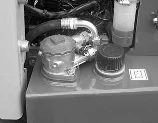
Checking Hydraulic Oil Level
1.Perform the “Mandatory Safety Shutdown Procedure” on page8.
2.Completely lower the lift arm and attachment.
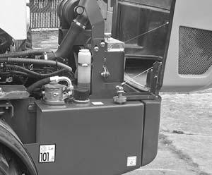
3.Check the hydraulic oil level by removing the dipstick (1, Figure 88), located in the engine compartment.
4.If hydraulic oil is required, allow the system to cool.
5.Slowly remove the oil fill cap (2, Figure 88). Allow the pressure to escape before completely removing the cap.
6.Add hydraulic fluid as required. See “Fluid Capacities/Lubricants” on page27.
7.Reinstall the oil fill cap.
Changing Hydraulic Oil and Filter
Replace the hydraulic oil if it becomes contaminated, after major repairs, and after 500 hours or one year of use.
1.Perform the “Mandatory Safety Shutdown Procedure” on page8.
2.Slowly remove the oil fill cap (2, Figure 88). Allow the pressure to escape before completely removing the cap.
3.Position a waste oil collection container, capacity 45liters (11gallons), underneath the hydraulic oil reservoir.
Important: Always dispose of hydraulic fluids according to environmental laws or take to a recycling center for proper disposal. DO NOT pour onto the ground or down a drain.
4.Remove the drain plug (1, Figure 89) and allow the oil to completely drain.
5.Unscrew the filter cover (3, Figure 88).
6.Remove the old filter element (1, Figure 90).
7.Clean the surface of the filter housing where the element seal contacts the housing. Put clean oil on the rubber gasket of the new filter element (1, Figure 90).
8.Install and tighten the new filter element (1, Figure 90) 3/4 turn past the point where the gasket contacts the filter head.
9.Reinstall the drain plug.
10.Reinstall the filter cover.
11.Refill the reservoir until the oil is between the two lines on the dipstick (1, Figure 88).
12.Start the engine and operate the hydraulic controls.
13.Stop the engine and check for leaks at the hydraulic oil filter and reservoir drain plug.
14.Check the oil level and add oil if necessary.
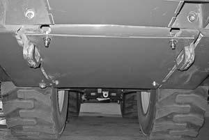
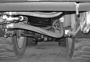
Planetary Axles
Changing Planetary Axle Oil
Replace the oil in the axles if it becomes contaminated, after the first 500 hours of service, and after 1500 hours or annually thereafter.
1.Warm the axles up to operating temperature.
2.Perform the “Mandatory Safety Shutdown Procedure” on page8. The machine must be parked on a level surface.
3.Complete the Changing Axle Wheel-Hub Oil and the Changing Axle Center Oil procedures.
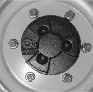
Changing Axle Wheel-Hub Oil
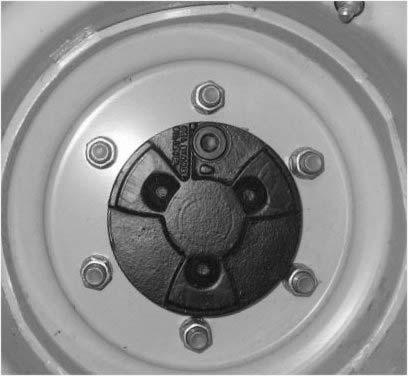
1.Rotate the oil drain/fill plugs (1, Figure 91) on the wheel hubs so they are positioned at the top as shown in the figure. Thoroughly clean the area around the plugs and slowly loosen and remove the plugs.
2.Position a waste oil collection containers, capacity 0.5liters (0.5 quarts) each, underneath the wheel hubs to catch oil as it drains.
Important: Always dispose of waste oil according to environmental laws or take to a recycling center for proper disposal. DO NOT pour onto the ground or down a drain.
3.Rotate the oil drain holes (1, Figure 92) on the wheel hubs so they are positioned at the bottom as shown in the figure. Allow the oil to completely drain from the hubs.
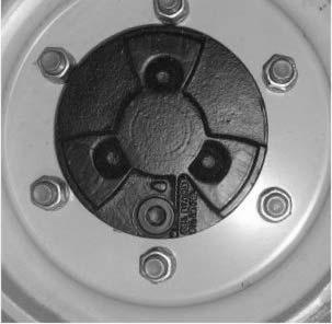
4.Rotate the holes on the wheel ends so they are positioned to the side as shown in Figure 93.
5.Add oil through the holes to the level line (2) stamped on the hub and shown in Figure 93. See “Fluid Capacities/Lubricants” on page27 for the specific oil type and grade.
6.Thoroughly clean the oil drain/fill plugs. Replace the plugs with new Orings and tighten to 70 Nm (52 lbf.ft.).
Changing Axle Center Oil
1.Thoroughly clean the area around the axle center fill plugs (1, Figure 94) and slowly loosen and remove the plugs.
2.Position a waste oil collection containers, capacity 2.5liters (2.6 quarts) front and 3.2 liters (3.4 quarts) rear, underneath the axle centers to catch oil as it drains.
Important: Always dispose of waste oil according to environmental laws or take to a recycling center for proper disposal. DO NOT pour onto the ground or down a drain.
3.Thoroughly clean the area around the axle center drain plugs (2, Figure 94) and slowly loosen and remove the plugs. Allow the oil to completely drain from the axle centers.
4.Thoroughly clean the axle center oil drain plugs. Replace the plugs with new O-rings and tighten the plugs to 70 Nm (52 lbf.-ft.)
5.Add oil through the oil fill holes (1) until it reaches the bottom of the holes. See “Fluid Capacities/Lubricants” on page27 for the specific oil type and grade.
6.Thoroughly clean the axle center oil fill plugs (1). Replace the plugs with new O-rings and tighten to 70 Nm (52 lbf.-ft.).


