
4 minute read
Loading and Transporting


Obey all applicable over-the-road regulations when transporting the machine. Check restrictions regarding weight, width and load length. The hauling vehicle, trailer and load must all be in compliance with regulations. Make sure the transport vehicle and the loading ramp are in proper working condition and have sufficient capacity for the load.
1.Park the transport vehicle on solid, even ground when loading.
2.Clean the loader and transport vehicle.
3.Attach ramps securely to the transport vehicle to prevent them from slipping during loading.
Do not use ramps inclined at an angle greater than 17° (30%). Clean dirt, mud, ice and snow from the ramps. Use metal loading ramps with a slip-resistant surface and beveled ends to prevent damage to the loader tires.
4.Engage the transport vehicle parking brake and chock the wheels.
5.Complete all steps in “Driving on Public Roads” on page52.
6.Carefully back the loader onto the transport vehicle, so that the heavy end of the loader is near the cab of the transport vehicle.
Caution Caution Warning
Do NOT adjust travel direction while driving up ramps. Instead, back off the ramps and re-align the machine with the ramps. Do not allow anyone to walk beside, behind or in front of the loader during loading and unloading. Always use the “slow” travel speed when loading the machine.
7.Perform the “Mandatory Safety Shutdown Procedure” on page8.
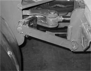
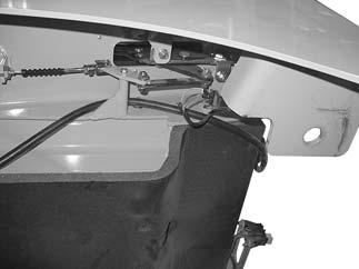
8.Secure the steering lock bar in the transport position using the cotter pins (1, Figure 64) provided.

9.Lock the cab, if so equipped.
10.Chock the machine’s tires to prevent them from rolling.
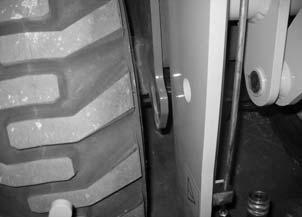
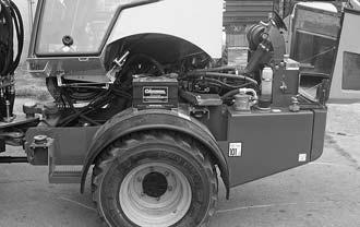
11.Secure the machine to the transport vehicle at the tie-down points (2, Figure 65 and 3, Figure 66) to prevent the machine from moving during transport in accordance with applicable over-the-road regulations.
Crane Lifting
Always close the cab doors (if applicable) and engine cover before crane lifting the machine. Stay clear from underneath the machine as it is lifted. Do not lift machine without proper equipment.
The crane must have a capacity greater then the weight of the machine. For machine weights, see “Weights (Equipped w/ 2-Post ROPS)” on page30.
1.Perform the “Mandatory Safety Shutdown Procedure” on page8.
2.Secure the steering lock bar in the transport position using the cotter pins (1, Figure 67) provided.
3.Lock the cab, if so equipped.
4.Close the engine cover, if necessary.
5.Connect spreader bar and chains to front and rear lift points as shown (Figure 68). The spreader bar should be long enough to prevent the chains from rubbing on the engine hood and the chains should be long enough to clear the ROPS structure.
6.Lift machine so it remains level (Figure 68).
Important: Chain must be routed over the rear bumper to prevent damage to machine.
Maintenance
Proper care and service improves machine operational readiness and service life. Perform maintenance as indicated in the “Maintenance Schedule” on page74, or earlier if required by conditions.
Read and understand the Safety Chapter, starting on page7, before servicing the machine. Follow all applicable warnings and instructions. Check for correct function after servicing the machine. Failure to follow instructions can result in injury or death.
Fluid leaks from hydraulic hoses or pressurized components can be difficult to see, but pressurized oil can have enough force to pierce the skin and cause serious injury. Always use a piece of wood or cardboard to check for suspected hydraulic leaks. Never use your hands. Obtain immediate medical attention if pressurized oil pierces the skin. Failure to obtain prompt medical assistance could result in gangrene or other serious damage to tissue.
Do not use the machine when maintenance is due. Postponed maintenance can result in a serious reduction of the service life of the machine, costly equipment failures, and contribute to unsafe operating conditions.
Warning Warning Caution Caution
Allow only trained and authorized personnel, with full knowledge of safe procedures, to perform machine maintenance and service.
Important: Malfunctions caused by unauthorized modifications and alterations are not covered under warranty.
Maintenance Schedule
Use the following table with the service procedures included in the this chapter, beginning on page73. For new machine operating guidelines, see “New Machines” on page51.
Important: The following maintenance intervals apply to average operating conditions and loads. Under extreme operating conditions, more frequent maintenance may be required. The hour meter indicates total operating time. Use the hour meter to determine when scheduled maintenance is due.
Caution
Do not postpone maintenance. Postponed maintenance can result in a serious reduction of the service life of the machine, more serious and costly equipment failures, and contribute to unsafe operating conditions.
Check, Clean and Inspect
Check, Clean and Inspect
1.Check every 2 hour after initial tightening until fastener torque stabilizes; every month thereafter.
Leakage Check
Lubrication and Filter Changes
1.After first 50 hours; every 250 hours thereafter.
2.Replace if needed.
Functional Check
Dealer Service
The following service items require special tools and knowledge and should be performed by your authorized Mustang dealer:
•Hydrostatic components
•Hydraulic system gear pump
•Valves
•Cylinders
•Electrical components other than battery and circuit breakers
Tilting the Platform
Warning
Always close the cab doors (if applicable) and open the engine cover before tilting the platform. Stay clear from underneath the platform as it is tilted. Always secure the tilt support when platform is tilted.
Tilting the Platform Up
1.Complete “Mandatory Safety Shutdown Procedure” on page8.
2.Open engine cover (4, Figure 71).
Note: Loader platform cannot be raised or lowered with the engine cover closed.
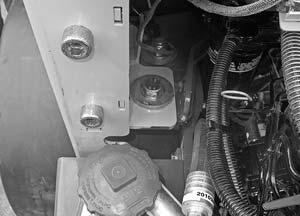
3.Remove platform lock-down nuts, bolts and washers from the left front (1) and left rear (3) of the loader platform (2). See also Figure 72 and Figure 73
4.Securely close the cab doors (if applicable).
5.Using ROPS, cab frame, and/or handles, manually tilt loader platform upward.
Note: The steering lock bar (Figure 64, page69) can be inserted in bracket (5, Figure 71) to provide additional leverage for tilting the platform.
Tilting the Platform Down
1.Open engine cover (4, Figure 71).
2.Disengage tilt support (1, Figure 74).
3.Using ROPS, cab frame, and/or handles, manually tilt loader platform (2, Figure 71) downward.
Note: The steering lock bar (Figure 64, page69) can be inserted in bracket (5, Figure 71) to provide additional leverage when lowering the platform.
4.Install platform lock-down nuts, bolts and washers onto the left front and left rear (1and 3, Figure 71) of the loader platform. See also Figure 72 and Figure 73.
5.Close engine cover (4, Figure 71).
Repair or Replace Loader Platform Switch
The platform switch (1, Figure 75) automatically shifts the drive pump to neutral when the platform is opened. Complete the following steps to repair or replace the platform switch:
Note: Do not manually operate the switch. Only access the switch to repair or replace.
1.Tilt up the operator’s platform. See “Tilting the Platform Up” on page77.
2.Turn battery disconnect switch to the “OFF” position.
3.Repair or replace platform switch, located at the left rear platform mount.
4.Turn battery disconnect switch to the “ON” position.
5.Tilt and secure the operator’s platform back into the operating position. See “Tilting the Platform Down” on page79.


