MVT 628 T
R E PA I R M A N U A L
HYDRAULICS CHECKING PRESSURES
Fig. 1
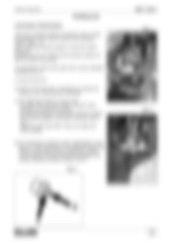
There are 2 pressure testing connections used to check the pressures of the various circuits of the hydraulic system: (Fig.1 / 2). Use a 0-600 bar pressure gauge to check the system pressures. Connect the line ref. 72340 and the pressure gauge ref. 58179 to these connections.
1
The directional control valve relief valve must be adjusted as follows (Fig. 3): 1) Undo the lock-nut 2) Screw in the screw Ref. 2 clockwise to increase the pressure, turn anticlockwise to decrease A) The relief valve pressure must be 235 bar (3857 PSI) with boom raised / lowered, boom retracted and accessory functions. To check the pressure, connect the 0-600 bar (0-8700 PSI) pressure gauge to the snap connection shown Fig. 1. Adjust the relief valve (Ref. 3-Fig. 4) to obtain the correct setting.
B) For checking the pressure of the compensation circuit, there is a snap connection on the right-hand side of the chassis on the bottom of the compensation cylinder. Fit the 0-600 bar (0-8700 PSI) pressure gauge to the pressure testing connection shown in Fig. 2.
Fig. 2
1
Fig. 3
2 1 Page
26


