3 minute read
Checking pressures


CHECKING PRESSURES
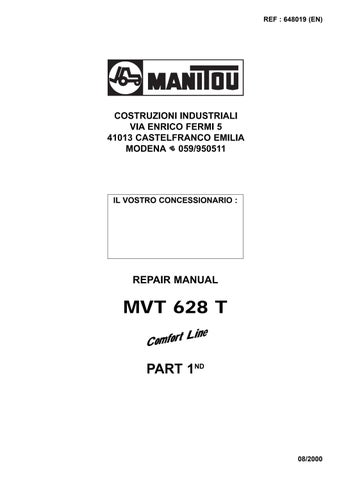
There are 2 pressure testing connections used to check the pressures of the various circuits of the hydraulic system: (Fig.1 / 2). Use a 0-600 bar pressure gauge to check the system pressures. Connect the line ref. 72340 and the pressure gauge ref. 58179 to these connections.
The directional control valve relief valve must be adjusted as follows (Fig. 3):
1) Undo the lock-nut
2) Screw in the screw Ref. 2 clockwise to increase the pressure, turn anticlockwise to decrease
A) The relief valve pressure must be 235 bar (3857 PSI) with boom raised / lowered, boom retracted and accessory functions.
To check the pressure, connect the 0-600 bar (0-8700
PSI) pressure gauge to the snap connection shown
Fig. 1.
Adjust the relief valve (Ref. 3-Fig. 4) to obtain the correct setting.
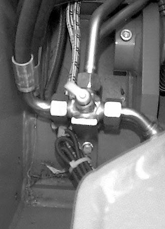
B) For checking the pressure of the compensation circuit, there is a snap connection on the right-hand side of the chassis on the bottom of the compensation cylinder.
Fit the 0-600 bar (0-8700 PSI) pressure gauge to the pressure testing connection shown in Fig. 2.
Fig. 3
1 2
Fig. 1
1
Fig. 2
1
C) The pressure of the compensation cylinder, bot tom end, must be set at 280 bar (3857 PSI).
Swing the fork support fully backward (forks pointing upward) and lower the boom slowly to read the setting pressure.
Adjust the valve on the directional control valve if necessary. (Ref. 1-Fig. 4) .
The damping valve of the compensation cylinder rod must be at 180 bar (2286 PSI).
Connect the pressure gauge to the main pressure circuit in the engine compartment (Fig. 5).
Swing the fork support fully forward (forks pointing downward), bring the engine to maximum rpm and read the pressure on the pressure gauge.
Adjust the pressure using the valve (Ref. 2-Fig. 4) if necessary.
D) The pressure of the boom extension cylinder must be set at 220 bar (3200 PSI).
Connect the pressure gauge to the main pressure circuit in the engine compartment (Ref. 1-Fig. 5).
Completely extend the boom to the limit position to read the pressure.
The pressure must be 220 bar (3200 PSI).
Adjust the relief valve if necessary (Ref. 4-Fig. 4).
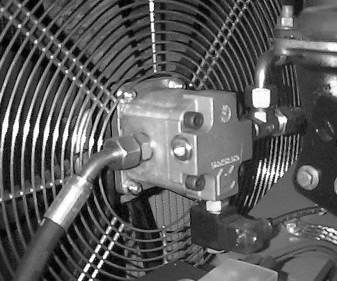
E) The pressure testing connections on the double pump in the right-hand side of the engine are used to check the pressure of the steering circuit, in the cooling fan and in the boom operating system.
To check the pressure in the steering circuit, connect the pressure gauge to the pressure testing connection.
- Lock the wheels completely to the left or right to the limit position. - Bring the engine to maximum rpm. - When the steering system is in the limit position, read the pressure on the pressure gauge. - The system is supplied with the pressure set at the optimum level of 160 bar (2285 PSI) (Ref. 1-Fig. 6).

1

3 4 2
Fig. 5
1
Fig. 6
1
- Remember to make a check if the power steering system itself is replaced. If the pressure is not at this level, adjust the relief valve to 160 bar(2285 PSI).
F) The speed of 3200 rpm is obtained when the pressure in the fan circuit is about 120 bar.
- The speed of 2000 rpm is obtained when the pressure in the circuit is about 50 bar.
- The fan speed must be measured with the engine at maximum rpm, with the aid of the rev-counter.
- The fan is of suction type.
N.B.: To facilitate adjustment of the speed (3200 rpm) a jumper should be placed across one of the two temperature probes during the adjustment. (Ref 1,2 - Fig.7 )
Fig. 7
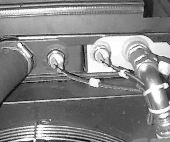
1 2
1