
3 minute read
Three Point Linkage

from Mahindra Tractor‘8000’ Series 8090 8100 4WD CABIN TIER-4 FINAL Operator's Manual - PDF DOWNLOAD

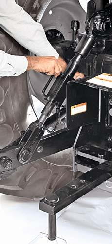
Adjustable Lift Rods
Use turn handle (A) on the adjustable lift rod to raise or lower the Telescopic Lower Link for side-to-side leveling of implement with respect to ground.

1.Raise lift rod turn handle (A) out of locking tab (B).
2.Rotate turn handle (A) clockwise to raise the lower link or anticlockwise for lowering.
3.After adjustment, make sure to engage handle (A) with locking tab (B). Always transport the implement with turn handle in this position.
Lateral Stabilizers

These are provided for adjustment of width between two lower links according to varying implement spans.
These enable to keep the implement in either FIXED or FLOATING position.

Placing the locating pin in (C) position shall keep the stabilizer and implement in “Fixed” position.
Placing the locating pin in (D) position shall keep the stabilizer and implement in “Float” position.
We recommend to use the fixed position while transporting the implement.
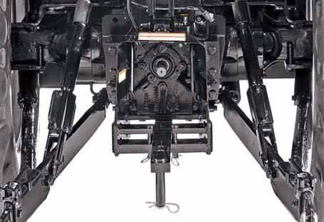
Swinging Drawbar
Tractor can be equipped with a drawbar for connecting to pull behind implements. It can swing from side to side and can be adjusted fore and aft. It can be set at various positions.
The distance between end of PTO shaft and implement / attachment pin hole can be set at three positions. In each position the dimensions achieved are as per chart.
Certain heavy equipment such as a loaded single axle trailer can place excessive strain on the drawbar. Strain is greatly increased by rough road and high speed. Static vertical load on drawbar should not exceed as stated in chart.
The drawbar can also be offset from the center on both sides. See your implement operator’s manual for drawbar positions.
The drawbar must be locked in center position when
1.Operating a drawbar pulled PTO driven implement.
2.Towing implements/Trailers on road or field.
Adjusting Drawbar Length
1.Remove lynch pin (A).
2.Pull drawbar pin (B)
3.Slide drawbar to desired position.
4.Insert the drawbar pin (B) in hole of drawbar.
5.Lock the drawbar pin (B) in position with Nut (A)
Using Swinging Drawbar


1.Remove “R” pin (D) of both pins (C).
2.Remove both pins (C).
3.Shift to next holes as desired.
4.Lock the “R” pins.
5.See your implement operator’s manual for drawbar positions.
Rear roll-over can result if pulling from wrong location on tractor. Hitch only to drawbar. Use three point hitch only with implements designed for its use, not as a drawbar.
Try to balance the load primarily on the implement wheels. Avoid overloading the drawbar. Add Jerrycan weights for improved stability. Engage the clutch smoothly, avoid jerking and use brakes cautiously to avoid jackknifing.
Attaching PTO Driven Implement
1.Turn Key to “OFF” position.
2.Disengage the SLIPTO lever.
3.Position the drawbar according to the requirement of implement and drive line.
NOTE : There are two holes at the front of drawbar. For drawn PTO driven implements, lock the drawbar pin in hole (1) for proper distance from end of PTO shaft end and implement / attachment pin hole, 14 inch for mPOWER 8090/8100.
For maximum traction and efficiency while pulling a trailer, lock the drawbar pin in hole (2) for proper distance from end of PTO shaft end and implement/ attachment pin hole, 12 inch for mPOWER 8090/8100.
4.Attach implement to tractor before connecting PTO driveline. Raise Hitch upwards if it is not to be used.
5.Rotate PTO shield upward for clearance.
6.With the engine still OFF, turn the shaft slightly by hand if necessary to line up splines. Connect driveline to PTO shaft. Pull out on shaft to be sure drive line is locked to PTO shaft.
7.Place PTO shield in downward position.
Stay Clear of PTO Shaft : Entanglement in PTO shaft can cause serious injury or death. Keep PTO shields in place at all times. Wear close fitting clothing. Stop the engine and be sure PTO drive is stopped before making adjustments, connections, or cleaning out PTO driven equipment.
Jerrycan Weights (Optional Fitment)
To obtain desired level of traction and stability, these weights are provided as optional fitment. The pin (E) is used for towing purpose.
With loader application on the tractor, these weights are to be removed. However the weight mounting bracket shall not be removed and the pin (E) with this bracket can be used for towing purpose.
If situation demands, the weights can be removed in pair :


1. Remove nut (A) and washer (B) from of threaded rod (C).
2. Remove weight (D) from both ends of the threaded rod (C).
3. Refit washer (B) and tighten nut (A) on threaded rod (C).
4.Remove the bolts (F) and washers (G) of Bracket Side support LH (H) from the Front axle support and other end from the Bracket front weight ballast and store.
5.Follow the same procedure for Bracket Side support RH removal.
For procuring "Jerrycan Weights" if required contact your Mahindra Dealer.
Handle all parts carefully, Do not Place your hands or fingers between parts. Use personal protecting equipment (PPE) as including Protective goggles, gloves and safety footwear. Failure to comply could result in death or serious injury.
Ballast weights are heavier make sure to use proper tools and lifting mechanism if required.


