9 minute read
Instrument Cluster

from Mahindra Tractor‘8000’ Series 8090 8100 4WD CABIN TIER-4 FINAL Operator's Manual - PDF DOWNLOAD

540/1000 PTO Operation Speed
This indicator shows 540/1000 PTO operation speed.
540E PTO Operation Speed
This indicator shows 540E PTO operation speed. This symbol will glow if the feature is equipped.
Trip Hour Counter
This is a LCD hour counter located under the tachometer. It is operated when the engine is running. Trip hour counter displays the running hours for the particular trip. The run hour is calculated in real time, i.e. 60 minutes of tractor run is calculated as 1 hour only. After 999.9 hours is completed, the count restarts from zero.
The blinking of the symbol indicates that the run time is counted on real time.
Trip Hour Reset Button
This is located on cluster bezel and is used to reset the trip hour meter as and when required. This can be done by continuously pressing the button more than 2 seconds.
Beeper Output Provision
The Beeper will beep at different rate during following conditions.
PriorityDescriptionBeeps/min
1High Coolant Temperature60
2Engine Low Oil Pressure50
3Transmission Oil Pressure40
4Battery Charging Indicator30
5Air Filter Clog10
6Service Reminder30
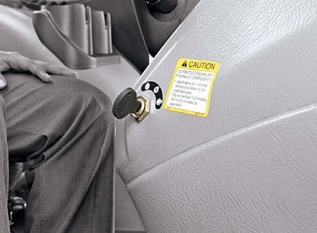
1.Ignition Key Switch
This is a key operated 3-way rotary switch located on RH side of front console. It operates in clockwise direction and the positions are as follows: i) OFF ii) IGNITION: This Position gives a readiness to the electrical circuit for operating electrical loads. iii) START: Turning the key to this position activates the starting circuit for starting the engine. When released, the key springs back to ignition position.
NOTE: Once the engine started, do not turn the key to starting position again, this will lead to damage the starter motor.
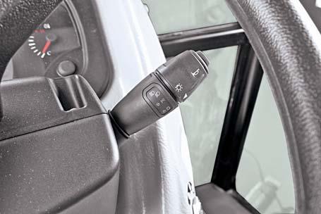
2.Steering Column Mounted Combination Switch (A)
This is multi-functional switch mounted on steering column. It consists of following operation switches.
1.Parking light/Position lamps
2.Head lamp low and high beam
3.Turn Signal
4.Horn
2.1 Parking light/Position lamps
This is 3-way rotary switch. The operations are as follows:
1.Off
2. Illuminates instrument cluster illumination lamp and position lamps.
3.Illuminates low/high beam of head lamp in addition to the position lamp with respect to the position of the lever.
2.2 Head lamp low and high beam
This is a 3 way lever switch. It operates in up and down direction and the operations are as follows.
Center:Operate Low beam of Headlamp
Down side:Operate High beam of Headlamp
Up side:Passing through (Momentary switch)

2.3 Turn Signal Switch
This is 3-way rotary lever switch. It operates in front and forth direction and the positions are as follows.
Center: OFF
Forward: Operates left turn signal lamp
Rearward: Operates right turn signal lamp
2.4 Horn (B)
This is push button switch. Pressing this switch will enable the horn and releasing it will disable the Horn.
Switches
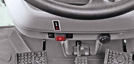
3. Hazard Switch (C)
This is push type switch located bottom side of front console. The operations are as follows.
On Position - Operates left and right turn signal lamp simultaneously. This operation can be performed even if the key switch is in OFF position.
This is a 3 way lever switch. It operates by lifting the lever then front and forth direction and the operations are as follows.
Center:Neutral position.
Forward:Vehicle move in forward direction.
Rearward:Vehicle move in reverse direction.
The lever can be engaged as follows,
1.Lift the F-R shuttle switch from its neutral position and shift to choose Forward or Reverse mode as desired.
2.F-R shuttle switch can be made without depressing clutch pedal.
The function of this switch is to automatically turn on the stop lamp when the brake pedal is pressed.
Reversing can be obtained at any speed. However, to protect mechanical parts from damage and for the operator safety, this operation should be made ONLY at speeds UNDER 10 kmph (6.2 mph). To correctly engage the reverse shuttle, reduce your speed to under 10 kmph (6.2 mph).
Moving the lever forward and backward without lifting, can damage the switch.
This switch will operate when the clutch pedal is pressed.
Don’t hold the lever while getting on or off the tractor.
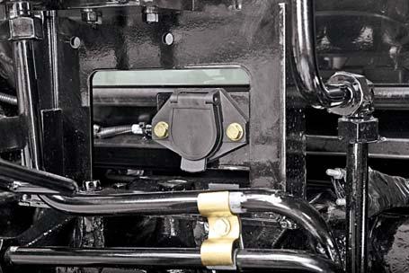
It is used to provide supply for any trailer which is attached at the rear.
The seven pins have the following functions.
Don’t hold the lever while tractor in running condition.
Seat is shown for Reference only
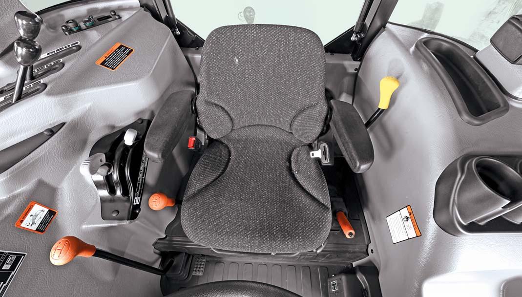
Controls
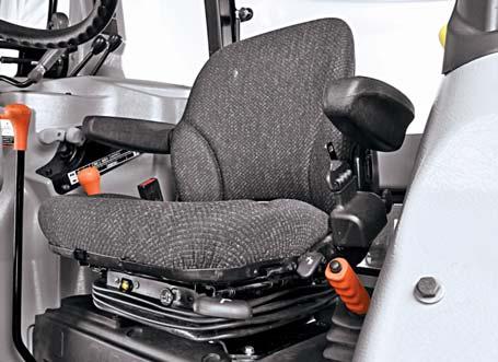
Operator Seat
The operator seat can be adjusted for position, tilt and height of operator. These adjustments are to be done prior to starting the engine.
Adjusting Seat Position
1.Sit on the operator seat.
2.Lift the lever (A) upwards & slide the seat forward or rearward to desired position.
3.Release lever to lock seat in position. Ensure that all controls can be accessed easily.
Height and Weight Adjustment
To achieve optimum seat suspension, press the knob (B) till you get the comfortable height and weight. This function can be activated with the ignition key at the Ignition position. It is operated by blower. Operator can hear a sound of air filling when the knob is pressed. Pull the knob, to reduce the seat height or as per the weight requirements.
Tilt Adjustment
To achieve optimum seat tilt, press lever (C) and press the back rest, till the desired angle of tilt is achieved.
Using Seat Belt
Use a seat belt when you operate to minimise chance of injury from an accident such as an overturn. Do not jump if machine tips.
Fasten Seat Belt
1.Pull belt end across operator lap.
2.Install tab into buckle. A click will be heard when the tab locks into the buckle.
Release Seat Belt
Press red button. The seat belt will automatically retract.
Attempting to adjust the seat while driving the tractor may cause the operator to lose control of the tractor.
Hand Throttle Operation
Use the Hand Throttle Lever to set a constant engine speed for stationary operation or for field operation wherever desired.
Increasing Engine Speed : Push away throttle lever from operator as indicated on the sticker.
Engine Tachometer Speeds : a.Low Idle Speed–850 ± 50 rpm b.Rated Engine Speed–2300 rpm c.High Idle Speed–2500 rpm ± 50 rpm
Decreasing Engine Speed : Pull throttle lever towards operator as indicated on the sticker.
Constant Speed Setting : Certain operations may require a particular engine speed. This can be achieved by resting the Hand Throttle Lever in a position where you get the desired engine speed.
Foot Throttle Operation
When tractor operation requires repeated speed change, use the foot throttle pedal to temporarily increase engine speed above hand throttle setting. We recommend to keep the hand throttle at minimum and use foot throttle when driving on road.
a.Set the hand throttle lever at desired rpm.
b.Depress foot throttle pedal to Increase Engine rpm.
c.Release foot throttle pedal to decrease Engine rpm to achieve the previous engine speed set by hand throttle lever.
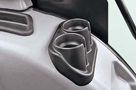

Can Holder
A can holder is located at the LH side of the operator’s seat on the LH console. It is designed for holding cup or drinkcans securely.
Controls
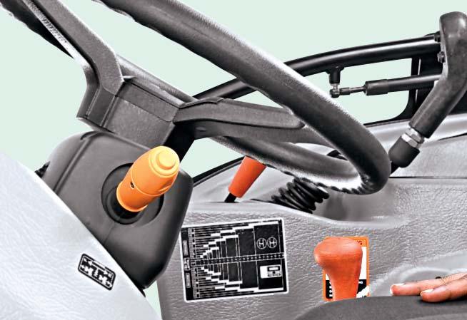
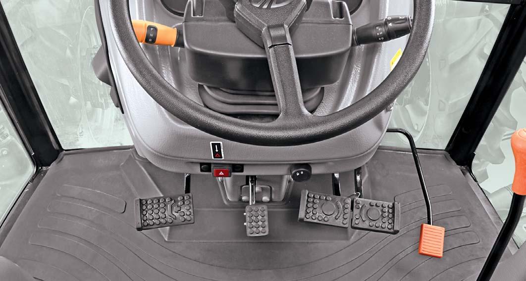
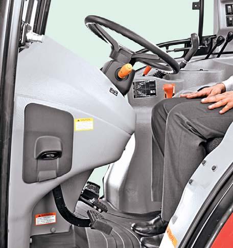
Tilt Steering
The steering can be tilted towards or away from the operator as per the need and convenience of operator and is recommended to be done in tractor parked condition.
Tilt Steering Adjustment
1.Park the tractor safely.
2.Press the tilt steering pedal by foot.
3.There are 3 adjustments of Steering position for tilt.
4.Tilt the steering wheel to desired position.
5.Release foot pressure on the pedal.
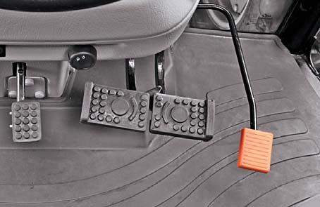
Brake
Two independent brake pedals are provided for L.H and R.H wheel braking to enable sharp turns during field operations.
To make a sharp turn to the left, depress L.H brake pedal (A).
To make a sharp turn to the right, depress R.H brake pedal (B).
The brakes can be latched together to act simultaneously by means of brake pedal latch (C) as follows,
1.Rotate brake pedal latch (C) clockwise until it locks into R.H. brake pedal (B)
2.Depress any of the brake pedal to slow or stop the tractor.
3.When brakes are applied with brake pedals latched together, the tractor should stop in a straight line. Check and adjust brake settings if the tractor is dragged to either side on applying brakes.
The Hand Throttle Lever should be brought to low idle rpm position before applying brakes.
Attempting to adjust the steering wheel while driving the tractor may cause the operator to lose control of the tractor.
Lock the steering wheel in position before driving the tractor.
Using unlocked brakes to stop the tractor at high speeds may cause accidental turning or tipping.
Lock pedals together when not using the turn brakes or for road travel.

Slow down before making a turn.
Do not apply independent brakes while an attachment is engaged with the ground. This can cause damage to the attachment , three point linkage of tractor and may also result in tipping of the tractor.
Controls
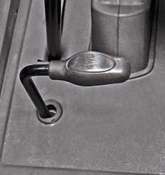
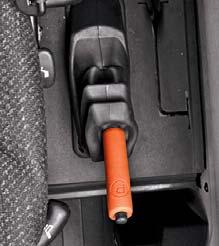
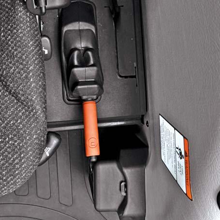
4WD Engagement Lever
This lever is located on LH side of operator’s seat. It is used to engage or disengage the drive to front wheels and is recommended to be done in tractor stand still condition.
1.Depress clutch pedal and stop the tractor motion completely.
2.Press the lever down to engage the drive.
3.Lift the lever upwards to disengage the drive.
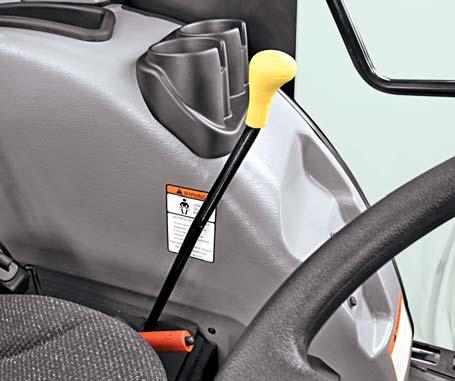
Parking Brake
The Parking brake lever is provided at the LH side of the operator’s seat on the rear platform.
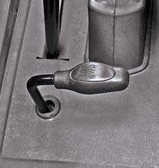
To engage the parking brake, pull the lever upwards fully. Parking brake indicator on instrument cluster will glow when the hand brake is applied.
To release the parking brake, pull the lever upwards slightly, press the locking button (A) and push the lever downwards. Parking brake indicator on instrument cluster will glow if you are driving with an incorrectly released hand brake. Always ensure to unlock parking brake before driving the tractor.
Driving with parking brake in applied condition, even if it is set partially, can overheat or damage the brakes and will result in poor braking.
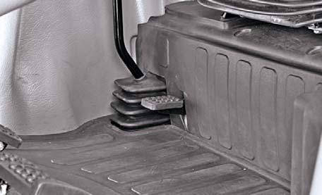
Differential Lock Pedal
This pedal located on the R.H. side of the Operator's Seat when depressed by heel pressure, operates a differential lock mechanism which locks both of the axle shafts together.
Its purpose is to overcome completely one-wheel slip encountered under bad field conditions, especially when ploughing or when hauling heavy trailers on slippery surfaces.
The condition where one wheel spins completely uselessly digging itself Into the soil while the other stands idle, is thus overcome resulting in saving fuel, brake wear and tire abuse.
Differential lock is designed for occasional use. Do not attempt to lock differential while, a.The tractor is in high speed. b.Turning tractor.
Clutch / Inching Pedal
Tractor is fitted with hydraulic control valve to engage / disengage drive to transmission PST clutch pack.
PST clutch pack transmits drive to the transmission and is operated by hydrualic control valve and clutch pedal. Depressing the clutch pedal fully disengages the drive to gear box for selection of different speeds.
The Differential Lock design is solely for the use with pneumatic tires. If steel wheels, girdles etc are fitted, the differential lock should be removed as a precaution.
Attempting to turn the tractor while differential lock is engaged may result in damage to transmission.
Resting the foot on the clutch pedal while driving reduces life of the clutch.

Do not use the clutch pedal to hold the vehicle or while driving on an uphill path. Use the parking brake instead.
Avoid use of partial clutch frequently.
The PTO power is obtained by engaging the hand operated SLIPTO lever (A).
IPTO Clutch
The term IPTO means, PTO is independent of main clutch. The power is transmitted to PTO shaft through an IPTO clutch which can be engaged or disengaged by IPTO clutch lever (A) located on LH side of operator’s seat.
The IPTO clutch is always to be kept in disengaged position and engagement of PTO drive can be achieved by putting the SLIPTO lever forward in engaged position.
To engage the PTO unit, proceed as under Move the SLIPTO clutch lever forward to engage the clutch. The PTO is now in engaged position.
To disengage the PTO unit, proceed as under Slowly move the SLIPTO clutch lever rearward to disengage the clutch.
The PTO is now in disengaged position.
The free play of the PTO clutch is preset at factory. It is not recommended to adjust the same through PTO clutch linkage.
NOTE : The clutch may require replacement due to normal wear, if loss of power to PTO shaft is observed when SLIPTO lever is engaged. Get the cause identified & rectified from the nearest Mahindra dealers under such circumstances.
Auxiliary Valve
The auxiliary valve is equipped with 2 lever operated valves. Each valve has four positions as follows : a.Float (F) Detent b.Lower (L) Detent c.Neutral (N) d.Raise (R) Detent

The lever returns to neutral position from lower or raise position when the cylinder is fully retracted / extended. Keep the levers in neutral position (N) when auxiliary valve is not in use.
NOTE: Additional Auxiliary valve can be fitted as Optional fitments, Contact nearest Mahindra Dealer for procurement and Installation.
When PTO drive is not in use keep the SLIPTO lever in disengaged position.
Firmly apply the parking brakes, place all gear shift levers in neutral and block all four wheels before operating any stationary PTO equipment Do not approach or work on the PTO shaft or equipment while the PTO is in motion. Shut-off engine and the PTO and wait for all movement to stop before working on the PTO or equipment.
Failure to comply will result in overheating the hydraulic oil and may cause injury or damage.


