
3 minute read
TASKS TO BE PERFORMED AFTER STARTING THE ENGINE

• Avoid using the Outrigger collective setting switch in a condition where installation height of each outrigger is different. Its use may make the machine significantly inclined or overturn.
• When stowing outriggers, be careful to avoid your body or clothes being trapped between outriggers and the machine body.
Caution
When 4 outriggers are installed equally at the same height, use the Outrigger collective setting switch. It facilitates smooth elevation of the machine.
1. See “Operation 2.2 Starting the Engine” and start the engine.
2 Turn the acceleration lever to right to change the engine speed to below medium speed

When 4 outriggers are installed equally in the same height, operate the ourtigger collecvtive setting switch as below:
Caution
On level ground, use the Outrigger collective setting switch to retract 4 outriggers all at once. It facilitates smooth lowering of the machine to the ground.
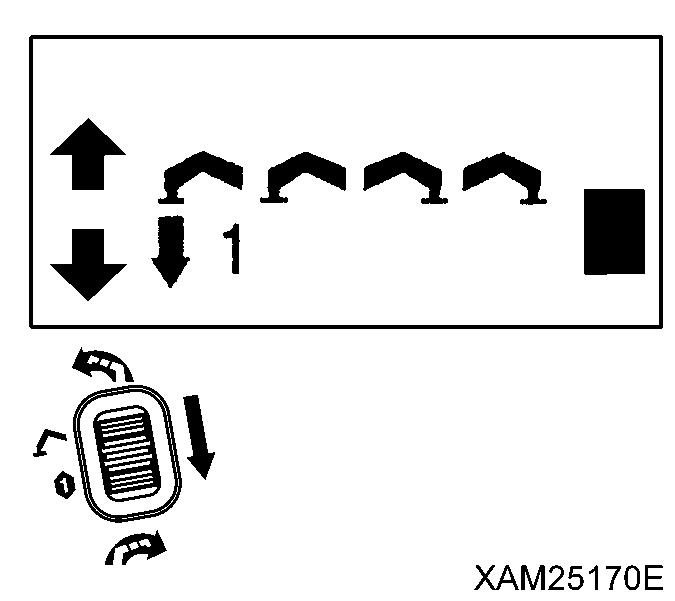
3. Open the outrigger switch cover and turn the Outrigger collective setting switch (16) upward to the IN position. Outrigger cylinders start retracting and the machine is lowered. Continue this operation until the rubber tracks stand firmly on the ground.

When 4 outriggers are installed unevenly in the different heights, operate the ourtigger individual setting switch as below:
When you control 2 of the individual switches at one time, only 2 in front (outriggers [(1)] and [(4)]) or only 2 in rear (outriggers [(2)] and [(3)]) shall be operated at the same time. When 2 outriggers in either left or right side are controlled at the same time, these may retract very quickly to cause crane tipping.


Caution
When 4 outriggers are installed unevenly in the different heights, use the outrigger individual setting switch to lower the machine slowly until the rubber tracks touch the ground.

4. Assure the number of the outrigger individual setting switch in the control panel, to determine the outrigger number to operate.

5. Open the outrigger switch cover and turn the Outrigger individual setting switch (15) respectively or 2 switches at the same time to the IN position
When the outrigger cylinder starts retracting and machine starts to lower, release the switch to return to the NEUTRAL position, once.
Continue the same operation of the other individual setting switches (15) to retract all the 4 outriggers so that the all are kept in the same level, then return to the NEUTRAL position, once. Repeat such operations until the rubber tracks stand firmly on the ground.
6 When the both left and right rubber tracks are completely lowered to the ground, turn the Outrigger collective setting switch (16) upward to the IN position
When Outrigger cylinders retract to raise outrigger top to the limit, release the Outrigger collective setting switch.
7. Push down the auxiliary starter switch to the STOP position The engine stops.


8. Turn the main starter switch key to the OFF position and remove the main starter switch key.
9. Pull up the lock lever (6) before pressing the whole lever stand (7) down to the “Travelling position”, then release the lock lever (6).

[2] TASKS TO BE PERFORMED UPON THE ENGINE STOP
1. Remove the snap pin (8) of the position pin (7) tip of the outrigger top (4) and pull out the position pin (7).
2. Push the innner box (5) into the outrigger top (4) and align the hole of the outrigger top (4) and the hole nearest to the end of the innner box (5).
3. Insert the position pin (7) to the hole of the outrigger top (4) and secure with snap pin (8).
4. Remove the snap pin (9) of the position pin (10) tip of the outrigger base (3) and pull out the position pin (10).
5. Lower the outrigger top (6) and align the hole of the outrigger top (6) and the hole of the lowest position in the outrigger base (3).
6. Insert the position pin (9) to hole of the lowest position in the outrigger base (3) and secure it with a snap pin (8) at the end.
Applicable to “Outrigger (1) and (4)”
7. Pull out the position pin (12) of the outrigger rotary (1) and rotate the outrigger rotary (1) inward.


8. Rotate the outrigger rotary (1) so that the sticker "Standard/Stow" affixed to its side and the sticker "Stow" affixed to the side of frame are aligned.


9. Insert positioning pin (12) to the hole with the sticker "Standard/Stow" of the outrigger rotary (1).
Applicable to “Outrigger (2) and (3)”
10. Pull out the position pin (12) of the outrigger rotary (1) and rotate the outrigger rotary (1) inward.
11. Rotate the outrigger rotary (1) so that the sticker "Standard" affixed to its side and the sticker "Stow" affixed to the side of frame are aligned.

12. Insert positioning pin (12) to the hole with the sticker "Stow" of the outrigger rotary (1)
13. When the outrigger is stowed, check each position pin is correctly inserted and secured by a snap pin or such.


