6 minute read
6.2.2 CALL OUT OUTRIGGER MODE NOTES


The OUTRIGGER MODE consists of “Outrigger collective setting mode (ALL)”and “Outrigger individual setting mode”. Use respective modes as shown below:

1. Push the Power button to turn ON the Transmitter. The “Crane mark” is displayed in the LCD screen for about 2 seconds.


Notes
In case the power is already ON, turn OFF once, and then push the Power button again for power ON.
2. While the “Crane mark” is shown in the LCD screen (for about 2 seconds), push the Speed/Mode button for 2 seconds.


The LCD provides the screen for selecting “CRANE MODE” or “OUTRIGGER MODE”.
3. Use the Hook raising and lowering Lever to shift the cursor ( or ), and push the Setting button when the cursor points to the “OUTRIGGER”.
4. The operation mode is already switched to the “OUTRIGGER MODE”, thus the “Outrigger mark” is exhibited.

Soon after, it enters into “Outrigger collective setting mode”, then the mark turns to “Outrigger collective setting mode (ALL) “.
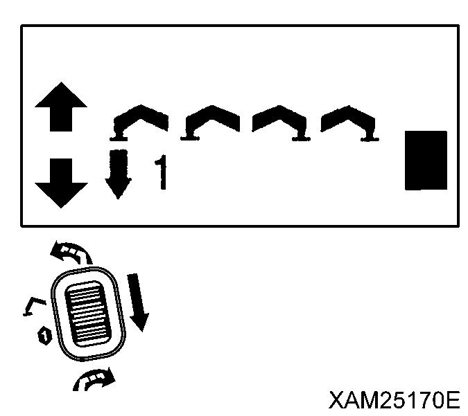
5. To shift to “Outrigger individual setting mode”, push the Speed/Mode button, while the LCD screen shows the “Outrigger collective setting mode (ALL)”. Then the mode is switched to “n”; the mark turns to “Outrigger individual setting mode ( )”.


Notes
Switching between “Outrigger collective setting mode” and “Outrigger individual setting mode” is alternated by each push of the Speed/Mode button.
7. CHECKING BEFORE OPERATION
Precautions shown in this section must be practiced prior to starting work, without fail. Serious injury or death may arise when these checks are neglected. Also refer to the section of “OPERATION 2.1 Checking before Operation” for checking of the crane structure.
In the event where any failure is revealed during checking, repair it, or contact us or our agents for services.
7.1 CHECKING BEFORE STARTING ENGINE
7.1.1 CHECKING BEFORE TURNING ON THE TRANSMITTER
For checking before Turning ON the Transmitter, ensure that the engine starter key is in the OFF position, and also the Receiver main switch is OFF. Otherwise, the engine may un-expectedly start and cause serious injury or death, while checking the Transmitter.
Perform the following inspections while the Transmitter power is OFF:
• Check the control levers, operation buttons, LCD screen, Accelerator lever and Grip for oily dirt or other contaminants.
Scrub away any dirt with a clean cloth.
• Check for foreign bodies such as particles of small stone or sand, caught into small openings in the vicinity of the control levers and/or Accelerator lever.
If found, remove such particles completely. In the event where such particles are caught in the small openings in the vicinity of the control levers and/or acceleration lever, they may disturb correct operations and cause un-expected motion of the Crane which may result in a serious accident.
• Check for any cracks and/or damage to the Transmitter enclosure, or impairment to the rubber cover of the operation levers and control buttons. Repair such cracks or damage immediately. Such cracks or damage may allow water to enter inside and bring troubles or failures to the Transmitter and cause a serious hazard.
• Check the smooth and correct actions of each of the operation lever and control button, and the Accelerator lever, also that they smoothly return to the each neutral position when the finger is released. Repair the operation levers, Accelerator lever and/or control button without delay, when any of them show an incorrect action.
Any failure to the operation levers, Accelerator lever and/or control button brings troubles or failures and may cause a serious hazard.
• Check the connection cable for any cracks, damage, bent or loose connection or damage in the connector section.
Repair or replace with a new cable, where such cracks, damages, or loose connection are present.
7.1.2 CHECKING AFTER TURNING ON THE TRANSMITTER
At the moment when the Transmitter is powered ON, make checks on following items:

[1] VERIFICATION OF THE LCD SCREEN SIGN AT POWER-ON
Push the Power switch to turn ON the Transmitter.
At this moment, confirm the mark as shown below, in the LCD screen.
Notes
In two seconds of this condition, it automatically enters into the “CRANE MODE”
[2] VERIFICATION OF THE LCD SCREEN SIGN AT THE “CRANE MODE”
1. Pull the Accelerator Lever to the full and check that acceleration rate indicated in the right part of the LCD screen is in the full throttle (with all the bars present).
2. Next, slack the Accelerator Lever slowly and check that acceleration rate indicated in the right part of the LCD screen decreases, reflecting the Accelerator Lever operation.
3. Then release your finger from the Accelerator Lever and check that acceleration rate indicated in the right part of the LCD screen shows idling (with all the bars absent).
4. Manipulate each operation lever and verify that each indication in the LCD screen is correct.
5. Manipulate each operation button and verify that each indication in the LCD screen is correct.
6. Verify that “START” is correctly displayed in the LCD screen when the Start/Reset button is pushed

7. Also, verify that “STOP” is correctly displayed in the LCD screen when the Stop/EMO button is pushed.


[3] VERIFICATION OF THE LCD SCREEN SIGN AT THE “OUTRIGGER MODE”

1. Push the Power switch once to turn OFF the Transmitter.
2. Push the Power switch again to turn ON the Transmitter. The “Crane mark” is displayed in the LCD screen for about 2 seconds.
3. While the “Crane mark” is shown in the LCD screen (for about 2 seconds), push the Speed/Mode button for 2 seconds.
The LCD provides the screen for selecting “CRANE MODE” or “OUTRIGGER MODE”.
4. Use the Hook raising and lowering Lever and shift the cursor ( or ), and push the Setting button when the cursor points out the “OUTRIGGER”.
Here, confirm that the “Outrigger mark” is exhibited, then it enters into the “Outrigger collective setting mode (ALL)”, soon after.
5. Manipulate each operation lever and verify that each indication in the LCD screen is correct.
Notes
In Outrigger collective setting mode (ALL), operation of any control lever will only result the same indication.


6. To shift to “Outrigger individual setting mode ( )”, push the Speed/Mode button, while the LCD screen shows the “Outrigger collective setting mode (ALL)”. Here, confirm that the “Outrigger individual setting mode ( )” is exhibited.
Notes
Switching between “Outrigger collective setting mode” and “Outrigger individual setting mode” is alternated by each push of the Speed/Mode button.


7. Manipulate each operation lever and verify that each indication in the LCD screen is correct.
7.1.3 CHECKING RECEIVER
Perform the following inspections:
• Check the Control Box (1), Main Switch (2), Monitor display (3), and Cable Connector (4) for oily dirt or other contaminants. Scrub away the dirt with a clean cloth.
• Check for any cracks and/or damages to the Control Box (1) or Monitor display (3). Repair any cracks or damage immediately. Cracks or damage may allow water to enter inside and bring troubles or failures to the Receiver, and may cause a serious hazard.
• Check the Main switch (2) and Cable Connector (4) for the loose conditions or damages. Repair immediately when any such loose conditions or damages are found. Such loose conditions or damages may cause errors or faults of the Receiver, which may result in a serious hazard.

• Toggle the Main switch (2) to ON and OFF alternately to verify that power is correctly turned ON or OFF.

• Turn ON the Transmitter,then toggle the Main switch (2) to ON, in addition, and confirm next that the two dots in the Monitor display as shown in the figure in the light blink.

Notes
In the condition that the Transmitter is not powered ON , or reception has an error, the Monitor display shows the error code, “E2”, when the Receiver is turned ON.
7.2 CHECKING AFTER STARTING ENGINE
Precautions shown in this section must be practiced prior to starting work, without fail. Serious injury or death may arise when these inspections are neglected. Further, refer to the section of “OPERATION 2.1 Checking before Operation” for checking of the crane structure.
Whenever any failures are revealed during such inspections, repair them, or contact us or our agents for services.
7.2.1 VERIFICATION FOR THE ENGINE START AND STOP
• Ensure that the boom and outriggers are in the stowed position, entirely . In the case where they are not in those positions, manipulate applicable levers of the Crane to make them stowed.
Otherwise, the Transmitter operation may cause damage to the Crane or tipping that results in serious injury or death.
• The Crane is inoperable in such an event where the LCD screen in the Transmitter shows an error message or the Monitor display in the Receiver shows an error code. Without fail, examine the cause of the error and perform appropriate service when any fault is identified, or contact us or our agents for services
[1] CHECKING ENGINE START OPERATION
1. Position the Starter Switch of the Crane to ON.
2. Set the travelling stand of the Crane to CRANE position.
3. Turn ON the Main switch of the Receiver.
4 Push the Power switch of the Transmitter, to power ON.
5. Then push the Horn button and confirm that the horn toots.
6. Use the Start/Reset button to check that the engine starts properly.
7. Check whether the indication “START” appears in the LCD screen, at that time.

Caution
Prior to starting the engine, perform the following practices of the Crane.
1. Set the Acceleration Lever to the medium speed (nealy middle in its stroke).
2. Pull out the choke knob
3. Return the choke knob to its initial position, when the engine starts.
[2] CHECKING ENGINE EMERGENCY STOP OPERATION
1. When the engine is started as in the above [1], try the Stop/EMO button to confirm that the engine absolutely stops.
2. Then check whether the indication “STOP” appears in the LCD screen.
Also confirm that the Monitor display in the Receiver shows the error code, “E1”, at that time.