5 minute read
4. COMPONENTS OF THE TRANSMITTER


(1) LCD Screen
(2) Start/Reset Button
(3) Stop/EMO Button
(4) Speed/Mode Button
(5) Setting Button
(6) Horn Button
(7) Power Switch
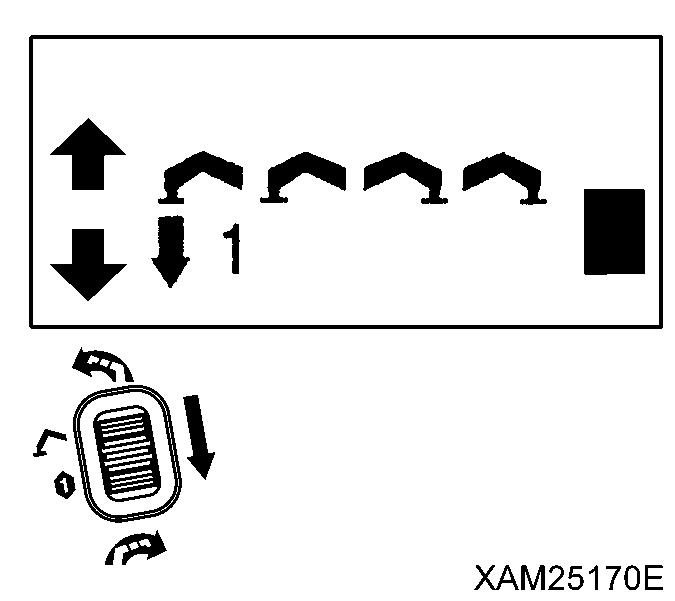
(8) Slewing/No.1 Outrigger Operation Lever
(9) Boom Telescoping/No.2 Outrigger Operation Lever
(10) Hook Raising and Lowering/No.3 Outrigger Operation Lever
(11) Boom derricking/No.4 Outrigger Operation Lever
(12) Accelerator Lever
(13) Grip
(14) Connection Cable
Caution
The remote control system provides the following safety functions:
• Abnormal Signal Detector Circuit
When the Main switch of the Receiver is turned ON this circuit checks the dispatch of Crane operation signals for 3 to 4 seconds. Thus, the Crane will not be immediately ready for operations.
When dispatch of any crane operation signals are noticed, power will be automatically OFF and the Crane stops.
To resume, push the Reset button of the Transmitter.
• Automatic Power OFF Circuit
Power of the Transmitter will be automatically OFF when the remote control of crane operations is discontinued for the specific time.
To resume, push the Power switch of the Transmitter to ON.
• Voltage Drop Limiter (for the Receiver)
The Receiver will automatically shut down in the event whereby the voltage of the battery drops below DC 9 volts.
This prevents malfunctions of the Crane due to voltage drop and the operation will resume automatically when the voltage is restored to DC 9 volts or higher.
[1] LCD SCREEN (1)
The LCD screen displays the status of the Transmitter in operation, the established values for each mode, or error messages by symbols, comments or signs.
[2] START/RESET BUTTON (2)
This button has two usages as below:
• To push this button starts the engine.
• This button resets the “Emergency Stop” and “Abnormal Signal Detect” conditions.

[3] STOP/EMO BUTTON (3)
This button also has two usages as below:
• To push this button stops the engine.
• In an emergency event where the Crane does not stop by normal operations, or such, this button provides the forced stop function.


[4] SPEED/MODE BUTTON (4)
This button also provides two usages as below:
• During crane operations, to push this button decelerates the operation speed.
• Whilst the crane operation is paused, this button provides the selection of the Transmitter operation modes. The current active mode will be displayed in the LCD screen.
[5] SETTING BUTTON (5)

• For each of the setting of the modes, use this button to select one of the choice from the menu in the LCD screen.

[6] HORN BUTTON (6)
Push this button to toot the horn.
[7] POWER SWITCH (7)
To push this button switches ON and OFF the power of the Transmitter. Each push will turn ON or OFF alternately.

[8] SLEWING/No.1 OUTRIGGER OPERATION LEVER (8)
This operation lever functions in two ways as below:
1. In the CRANE MODE, this lever controls slew of the Crane structure:
• Counterclockwise: Push the upper end of the lever.

• Neutral: Release your finger from the lever.
• Clockwise: Push the lower end of the lever.
2. In the OUTRIGGER MODE, this lever controls extension (setting) and retraction (stowing) of either only No.1 or all of the outriggers at once:
• Retraction (stowing): Push the upper end of the lever.
• Neutral: Release your finger from the lever.
• Extension (setting): Push the lower end of the lever.
[9] BOOM TELESCOPING/No.2 OUTRIGGER OPERATION LEVER (9)
This operation lever functions in two ways as below:
1. In the CRANE MODE, this lever controls the telescopic boom length:
• Boom extension: Push the upper end of the lever.
• Neutral: Release your finger from the lever.
• Boom retraction: Push the lower end of the lever.
2. In the OUTRIGGER MODE, this lever controls extension (setting) and retraction (stowing) of either only No.2 or all of the outriggers at once:
• Retraction (stowing): Push the upper end of the lever.
• Neutral: Release your finger from the lever.
• Extension (setting): Push the lower end of the lever.

[10] HOOK RAISING AND LOWERING/No.3 OUTRIGGER OPERATION LEVER (10)
This operation lever functions in three ways as below:
1. In the CRANE MODE, this lever controls raising and lowering the hook:
• Hook raising: Push the upper end of the lever.
• Neutral: Release your finger from the lever.
• Hook Lowering: Push the lower end of the lever.
2. In the OUTRIGGER MODE, this lever controls extension (setting) and retraction (stowing) of either only No.3 or all of the outriggers at once:
• Retraction (Stowing): Push the upper end of the lever
• Neutral: Release your finger from the lever.
• Extension (setting): Push the lower end of the lever.
3. In the A MODE and OPERATION MODE, this lever is used as a cursor key by “ and ” .


[11] BOOM DERRICKING/No.4 OUTRIGGER OPERATION LEVER (11)
This operation lever functions in two ways as below:
1. In the CRANE MODE, this lever controls the boom derricking angle:
• Boom raising: Push the upper end of the lever.
• Neutral: Release your finger from the lever.
• Boom lowering: Push the lower end of the lever.
2. In the OUTRIGGER MODE, this lever controls extension (setting) and retraction (stowing) of either only No.4 or all of the outriggers at once:
• Retraction (stowing): Push the upper end of the lever.
• Neutral: Release your finger from the lever.
• Extension (setting): Push the lower end of the lever.

[12] ACCELERATOR LEVER (12)
The Accelerator lever controls the flow rate of the control valves and the engine speed or output.
• Low idling: Release your finger from the Accelerator lever.
• Full throttle: Squeeze the accelerator lever to the full.
Notes
• The Accelerator lever itself cannot control either flow rate of the control valves or the engine speed when it is manipulated alone.
When used in conjunction with any of the other operation levers, the Accelerator lever launches the specified operation of the Crane in the idling state of the engine, then when it is manipulated further the engine speeds up This is progressive until the full throttle position is reached.
• The Accelerator lever does not control outriggers.
• The acceleration rate is always indicated in the right part of the LCD screen during crane operations. (See the figure in the right.)

[13] GRIP (13)
The Transmitter is designed for one hand control in general. Levers and buttons can be manipulated by your thumb, while the accelerator lever can be triggered by your forefinger. Other fingers should grab the grip to hold the Transmitter.
[14] CONNECTION CABLE (14)
The connection cable is a cable between the Transmitter and Receiver.


Before and after the operation, always check this connection cable for any cracks, damage, or bending. Also check the receptacle for any damage.
[15] STORAGE CASE (15)
The Storage case is a compact bag for protection of the Transmitter.

Before putting it into this case, ensure that the power of the Transmitter is OFF.
[16] HOOK BELT (16)
During the operation, this belt prevents the Transmitter from falling down to the ground, when the operator drops it by mistake. Hook one end of the hook belt (16) to the Transmitter and attach another end to the operator‟s waist belt etc.