
11 minute read
DESCRIPTIONS OF SWITCHES ON MOMENT LIMITER DISPLAY UNIT

• When entering the number of wire falls, verify the actual used number of wire falls and make sure to set up correctly.
Entering incorrect number of wire falls may prevent pre-warnings and boom auto-stop even when the overload is being approched, and thus may result in crane damage or machine trip that may result in serious accidents.
Advertisement
• Stop the crane operation when changing the number of wire falls using the number of wire falls selector switch.
Changing the number of wire falls during the crane operation can cause unexpected accidents.
• Perform the crane operation always after matching the number of wire falls displayed on the moment limiter and the actual number of wire falls. Mistaking the number of wire falls causes serious accidents.
The wire rope has the safe load per rope fall determined. Determine the number of wire falls according to the maximum load to be hoisted. With this machine, the hook for four wire fall of rope is referred to as the standard specifications
The last status of the set number of wire falls is memorized even if the starter switch is turned to the OFF position.
Use this switch to change the number of wire falls.
• Keep pressing the switch for 2 seconds or more. The setting changes from “4-falls” to “1-fall”. At the same time, the wire falls display LED changes from “4-falls” to “1-fall”, indicating that the setting has changed.
• Then each time you press the switch for 2 seconds or more, the setting of the wire falls changes from “1-fall” to “2-falls”, and then from “2-falls” to “4-falls”.
Notes
When changing the setting, right after doing so, release your finger from the switch, and then press the switch again.
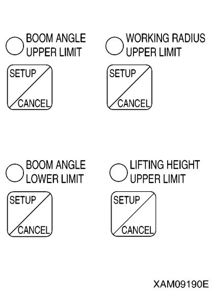
set or cancel the boom angle upper limit.
[SETUP]
With no upper limit value being set, set the boom to the angle you would like, and press the switch for 2 seconds. The boom angle at this point is set as the upper limit. At the same time, the LED lights up indicating that the upper limit value was set.
To enable this setting, turn the key switch to the ON position again after turning it to the OFF position, or lower the boom by “10 degrees” or more from the set boom angle to get out of the pre-warning zone while the engine is being started.
Notes
Be sure to verify that the boom automatically stops at the set angle before performing the actual operation. If the boom does not stop automatically, re-set the boom angle using the procedure above.
When the boom reaches the pre-warning zone or stops at the upper limit with the boom angle upper limit set, the boom angle upper limit LED flashes. [CANCEL]
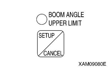
With the upper limit value being set (LED ON), press the switch for 5 seconds. The current upper limit value setting will be cleared. At the same time, the LED goes off indicating that the upper limit value setting is cleared.
Notes
The setting and canceling will not repeat even if you keep the switch pressed for more than 2 seconds. Let your finger go off the switch and press the switch again.
3. BOOM ANGLE LOWER LIMIT SWITCH AND LED (RED)
Use this switch to set or cancel the boom angle lower limit.
[SETUP]
With no lower limit value being set, set the boom to the angle you would like, and press the switch for 2 seconds. The boom angle at this point is set as the lower limit. At the same time, the LED lights up indicating that the lower limit value was set.
To enable this setting, turn the key switch to the ON position again after turning it to the OFF position, or raise the boom by “7 degrees” or more from the set boom angle to get out of the pre-warning zone while the engine is being started.
Notes
Be sure to verify that the boom automatically stops at the set angle before performing the actual operation. If the boom does not stop automatically, re-set the boom angle using the procedure above.
When the boom reaches the pre-warning zone or stops at the lower limit with the boom angle lower limit set, the boom angle lower limit LED flashes. [CANCEL]
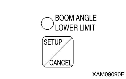
With the lower limit value being set (LED ON), press the switch for 5 seconds. The current lower limit value setting will be cleared. At the same time, the LED goes off indicating that the lower limit value setting is cleared.
Notes
The setting and canceling will not repeat even if you keep the switch pressed for more than 2 seconds. Let your finger go off the switch and press the switch again.
4. WORKING RADIUS UPPER LIMIT SWITCH AND LED (RED) Use this switch to set or cancel the working radius upper limit. [SETUP]
With no upper limit value being set, set the boom to the working radius you would like, and press the switch for 2 seconds. The working radius at this point is set as the upper limit. At the same time, the LED lights up indicating that the upper limit value was set.
To enable this setting, turn the key switch to the ON position again after turning it to the OFF position, or reduce the working radius by “1.3 m” or more from the set working radius to get out of the pre-warning zone while the engine is being started.
Notes
Be sure to verify that the boom automatically stops at the set working radius before performing the actual operation. If the boom does not stop automatically, re-set the working radius using the procedure above.
When the boom reaches the pre-warning zone or stops at the upper limit with the working radius upper limit set, the working radius upper limit LED flashes. [CANCEL]
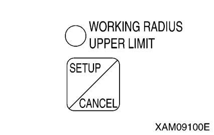
With the upper limit value being set (LED ON), press the switch for 5 seconds. The current upper limit value setting will be cleared. At the same time, the LED goes off indicating that the upper limit value setting is cleared.
Notes
The setting and canceling will not repeat even if you keep the switch pressed for more than 2 seconds. Let your finger go off the switch and press the switch again.
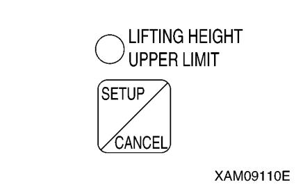
5. LIFTING HEIGHT UPPER LIMIT SWITCH AND LED (RED)
Use this switch to set or cancel the lifting height upper limit. While the lifting height is restricted by detecting the height of the tip of the boom, the lifting height on the display panel shows the lifting height when the hook was raised to the over hoist detection status.
[SETUP]
With no upper limit value being set, set the boom to the lifting height you would like, and press the switch for 2 seconds. The lifting height at this point is set as the upper limit. At the same time, the LED lights up indicating that the upper limit value was set. To enable this setting, turn the key switch to the ON position again after turning it to the OFF position, or reduce the lifting height by “1.3 m” or more from the set lifting height to get out of the pre-warning zone while the engine is being started.
Notes
Be sure to verify that the boom automatically stops at the set lifting height before performing the actual operation. If the boom does not stop automatically, re-set the lifting height using the procedure above.
When the boom reaches the pre-warning zone or stops at the upper limit with the lifting height upper limit set, the lifting height upper limit LED flashes.
[CANCEL]
With the upper limit value being set (LED ON), press the switch for 5 seconds
The current upper limit value setting will be cleared. At the same time, the LED goes off indicating that the upper limit value setting is cleared.
Notes
The setting and canceling will not repeat even if you keep the switch pressed for more than 2 seconds. Let your finger go off the switch and press the switch again.
6. CANCEL SWITCH
Use this switch to cancel the all setting sets in the section 2 to 5 above.
• Press this switch and “CHECK” switch at the same time for 5 seconds or more.
The all value sets in the section 2 to 5 above will be canceled.
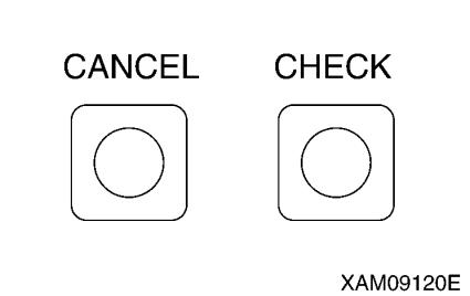
7. CHECK SWITCH
Use this switch to verify the values set in the section 2 to 5 above.

• Press this switch. Every time the switch is pressed, the set value will be displayed in the following order.
(1) “Boom angle upper limit value” is displayed at the boom angle display section
(2) “Boom angle lower limit value” is displayed at the boom angle display section.
(3) “Working radius upper limit value” is displayed at the working radius display section
(4) “Lifting height upper limit value” is displayed at the lifting height display section.
(5) Returns to the original display.
Notes
• When a set value is displayed, the LED for its setting switch section flashes at the same time.
• If no switch was pressed for 5 seconds or another switch was pressed with a set value being displayed, the display goes back to the original display.
• The display will be a blank for the item to which no value is set.
• The display sections other than for the corresponding items will be blank.
[2]
Descriptions Of Moment Limiter Display Unit
For LEDs not described in this section, see “Operation 1.4.4 Names of moment limiter display unit”.
1. ACTUAL LOAD DISPLAY SECTION
This section constantly displays the actual load of the hoisted load during the crane operation.
The actual load indicates the total weight of the hoisted load and lifting ring excluding the hook weight.
If “0.0” to “0.1” is displayed when nothing is being hoisted, the system is normal.
If the value displayed is out of this range, contact us or our sales service agency
2. RATED TOTAL LOAD DISPLAY SECTION
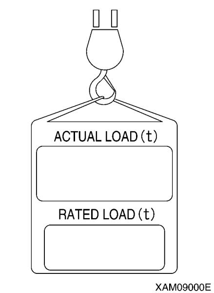
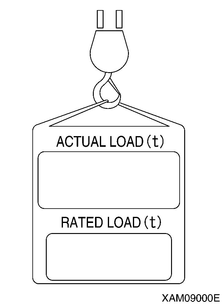
This section displays the number of wire falls on the hook, working radius, currently hoistable rated total load (hook weight + lifting ring weight + load to be hoisted) computed out of the conditions such as the degree of outrigger extension.
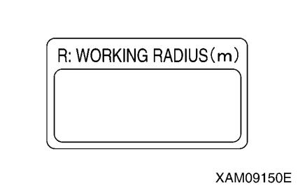
3. WORKING RADIUS DISPLAY SECTION
This section constantly displays the current working radius during the crane operation.
The working radius is the horizontal distance from the crane slewing centre to the centre of the hook.
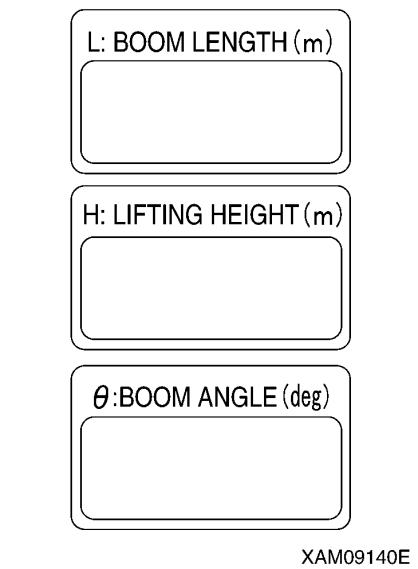
4. BOOM LENGTH DISPLAY SECTION
This section constantly displays the current boom length during the crane operation.
The boom length is the distance from the boom foot pin to the sheave pin at the end of the boom.
5. LIFTING HEIGHT DISPLAY SECTION
This section constantly displays the current lifting height during the crane operation.
The lifting height is the vertical distance from the ground to the bottom of the hook.
6. BOOM ANGLE DISPLAY SECTION
This section constantly displays the current boom angle during the crane operation.
The boom angle is the angle the boom and the horizontal line form.
7. OVER WINDING LED (RED)
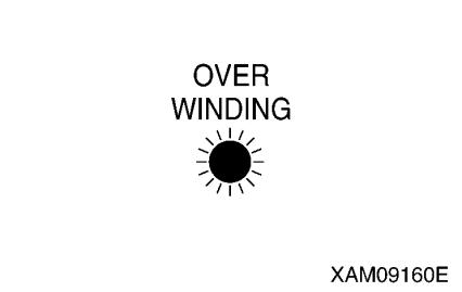
This LED flashes up when the hook is overwound, and issues overwinding warning and causes an automatic stop. This LED also flashes when the hook is stowed during the hook stowing operation. This is normal.
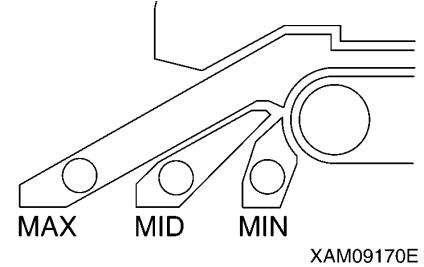
8. OUTRIGGER EXTENSION LED (ORANGE)
The LED lights up to indicate the outrigger extension status.
• If any of the four outriggers has not properly reached the maximum extension position, the “MIN” LED lights up.
• If all the four outriggers reach the maximum extension position, the “MAX” LED lights up. Even if you thought you had set the outriggers at the maximum extension position, the “MIN” LED lights up if any of the outriggers did not properly reach the maximum extension position.
Notes
This machine is not capable of detecting the middle extension position. Please be careful as "MID" LED does not light.
9. LOAD FACTOR DISPLAY (ORANGE)
This display indicates the status of the moment limiter load factor by its illumination.
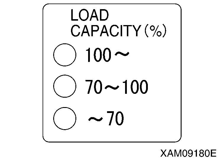
• Where the load factor is less than 70% of the rated total load, "70" LED lights up.
• Where the load factor is 70 to less than 100% of the “rated total load, "70 - 100" LED lights up.
• Where the load factor is 100% or higher than the rated total load, "100 -" LED lights up.
1.4.5 OTHER MOMENT LIMITER FUNCTIONS
[1] WORKING ENVELOPE RESTRICTION WARNING
When the working envelope gets close to the set restriction value, a warning is issued to notify the operator and people around of the situation.
The last status of the set value for the working envelope restriction is memorized even if the starter switch is turned to the OFF position.
Notes
See “Operation 1.4.4 [1] Descriptions of Switches on Moment Limiter Display Unit” for how to set the value for working envelope restriction.
When the working envelope has been set, the restriction will be as follows.
1. SAFETY ZONE
• The appropriate working envelope restriction LED (red) lights up.
• Green of the working status lamp lights up.
2. PRE-WARNING
• The appropriate working envelope restriction LED (red) lights up.
• The alarm sounds intermittently.
• Yellow of the working status lamp lights up.
3. LIMIT WARNING
• The appropriate working envelope restriction LED (red) lights up.
• Red of the working status lamp lights up.
• The alarm sounds continuously.
• The appropriate operation of the crane stops automatically.
[2] OVER HOIST DETECTOR
Caution
Pay attention to the distance between the hook and boom when raising the hook. Extending the boom also raises the hook. Always check the hook height when extending the boom.
When you overwind the hook when raising the hook or extending the boom,
• The “Overwinding” LED (red) flashes.
• The alarm sounds continuously. (It stops sounding when the operation lever is released.)
• The hook raising, boom extending and boom raising operation stop automatically.
In case of auto stop, immediately perform the recovery operation. Perform hook lowering and boom retracting operations as recovery operations.
[3] BOOM UPPER LIMIT DETECTION
When the boom is raised and the boom angle reaches “about 77 degrees”, the boom raising operation stops automatically.
[4] BOOM LOWER LIMIT DETECTION
When the boom is lowered and the boom angle reaches “about 3 degrees”, the boom lowering operation stops automatically.
1.4.6 MOMENT LIMITER STARTING STATUS CAUTION
• If the red of the working status lamp does not go off after completing the functional check of the moment limiter, be sure to contact us or our sales service agency.
• If the travelling lever stand is set in the "Travel Position", the Moment Limter is not turned ON. To turn it ON, don't forget to set the travelling lever stand in the "Crane Operation Position".
The moment limiter checks its function for 2 seconds when the starter switch is turned to the ON position. Meanwhile,
• The red of the working status lamp lights up.
• All the LEDs light up.
Then, if the moment limiter and the sensors are normal upon the completion of the functional check of the moment limiter, the red of the working status lamp goes off and green of the working status lamp lights up indicating that the machine is ready for use.
1.4.7 MOMENT LIMITER ERROR CAUSES AND ACTIONS TO BE TAKEN
The moment limiter displays an error code at the “rated total load” display section on the display panel to notify the error.
If an error code shown in the table below was displayed, contact us or our sales service agency
E1L
The input to pressure sensor 1 is lower than the specified value.
E1H
The input to pressure sensor 1 is higher than the specified value.
Check the installation of the pressure sensor 1.
E2L
The input to pressure sensor 2 is lower than the specified value.
E2H
The input to pressure sensor 2 is higher than the specified value.
Check the installation of the pressure sensor 2.
E3L
The input to angle detector is lower than the specified value.
Check the installation of the angle detector.
E3H
The input to angle detector is higher than the specified value.
E4L
The input to length detector is lower than the specified value.
E4H
The input to length detector is higher than the specified value.
Check the installation of the length detector.
EAD
The AD converter at the converter section is not functioning properly.
Turn the starter switch to the OFF position and then to the ON position again. If an error is displayed again, change the converter.
ERS
The communication between the converter section and the display unit is not carried out properly.
• Check the cable between the display unit and the converter. If the cable is normal, change the converter.
• Check the fuse built-in the converter.
E-E
Error with calibration memory. This error is also issued when calibration has not been done yet.
No displayed
Turn the starter switch to the OFF position and then to the ON position again. If an error is displayed again, change the display unit.
Check the fuse built-in the display unit.
