
4 minute read
TRAVELLING LEVER STAND (7) AND LOCK LEVER (6)

• Before setting the travelling lever stand to “Travelling position”, be sure to stow the crane and let the machine assume travelling position. Travelling with the crane not in travelling position, may cause it to tip over and cause a serious accident .
• When pulling up the travelling lever stand lock lever, be careful not to contact the travelling lever, as it may cause the undercarriage to move.
Use this stand to switch the work state of the machine (Travelling control, Crane operation, Stowing position).
• Travel: Pull up the lock lever (6) before erecting the entire lever stand (7) forward to the "Travelling Control Position". The machine is in "Travelling Control Position" when the bottom end of lock lever (6) fits into the guide groove (B)
• Crane: Pull up the lock lever (6) before pressing the whole lever stand (7) down to the "Crane Operation Position". The machine is in "Crane Operation Position" when the end of lock lever (6) fits into the guide (C)
Notes
• Where the travelling lever stand is set in the“Travelling position” , only travelling operation is available. In such a condition, respective crane control levers and outrigger setting switchs are disabled to manage their functions.
• Also, where the travelling lever stand is set in the “Travelling position”, any outrigger setting or crane operations by the Remote Controller are not workable.
• For any outrigger setting or crane operations, set the travelling lever stand in the "Crane Position".

• Stow Position :Pull up the lock lever (6) and grab the Grip (3) to press the whole lever stand (7) down to the "Stow Position". The machine is in "Stow Position" when the end of lock lever (6) fits into the guide (A).
Notes
When the travelling lever stand is set in the "Stow Position", the whole of the stand can be positioned within the back end of the carrier. (Full length: 2000mm) This position may be convenient during transportation or when the parking area is restricted.
1.2.2 DESCRIPTION OF EACH SWITCH
[1]
STARTER SWITCH (17)
Use this switch to start and stop the engine.
• OFF : You can insert/remove the key at this position. All the switches in the electrical system are turned off and the engine stops.
• ON : Electricity runs into all the circuits.
• START: When the engine has started, release your finger from the key. The key automatically returns to the ON position.
[2]
CHOKE KNOB (10)
This knob is to be used when ambient temperature is low and engine is difficult to start.
Use the choke in the following manner:
1. Pull the knob all the way back.
2. Place the starter switch at “START” position.
3. When the engine has started, press the knob to original position.


[3]
HEADLIGHT SWITCH (16)

Use this switch to turn on the headlights on front of the machine.
• ON: Pull the switch toward you forward. The headlights turn on.
• OFF: Push the switch forward. The headlights turn off.
Notes
The headlights do not light up even if the headlight switch is operated when the starter switch is at the OFF position.
[4]
HORN SWITCH (8)
Use this switch to honk the horn.
• Honking the horn: Press the switch.
Notes
• The horn will stop when you release your finger from the switch.
• The horn switch is provided on the crane operation side as well.
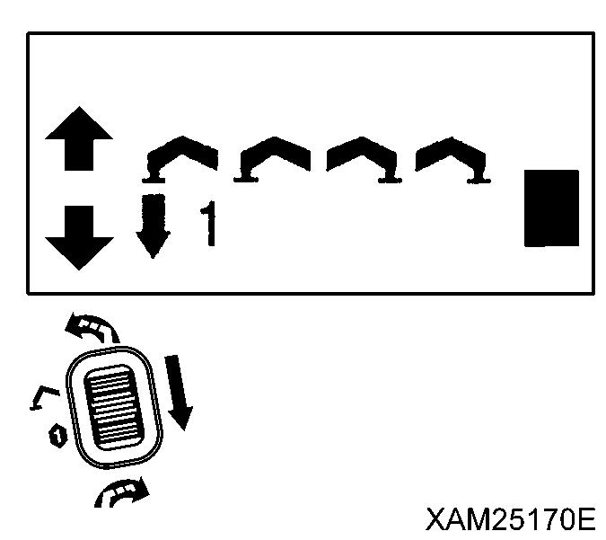
[5] TRAVELLING HIGH-SPEED SWITCH (9)
Use this switch to change the mode of the machine travelling speed.
• ON: Push the switch forward. The travelling speed mode changes to high-speed travelling mode.
• OFF: Push down the switch toward you. The travelling speed mode changes to low-speed travelling mode.
Notes
• In high-speed travelling mode, you may feel difficulty in changing travelling direction. In such event , it is advisable to switch to low-speed travelling mode.
• During loading to or un-loading from a truck, use low-speed travelling mode since the footing of the operator may become insecure
• When travelling over uneven terrain, footing of the operator as well as the machine position may become vulnerable. Switch to low-speed travelling mode in such conditions.
[6] ENGINE EMERGENCY STOP SWITCH (5)
Use this switch in case of an error in the machine to stop the machine for emergency.
• ON: Press the switch. The engine stops.
• OFF: Turn the switch clockwise (direction of the arrow in the right figure). The switch returns to the original position.
Notes
When restarting the engine after emergency stop, be sure to turn the engine emergency stop switch to the OFF position before starting the engine.


1.2.3 DESCRIPTION OF EACH METER AND LAMP
[1] HOUR METER (11)
This meter shows the total running hours of the machine. Use this value as the reference for periodical check interval. The value in the meter increases when the engine starts. The value does not change in the condition where the engine stops, though the starter switch is in ON position.

[2] BATTERY CHARGE MONITOR (15)
This monitor indicates errors in the battery charge system. If it lights up when the starter switch is turned to the ON position and goes off as the engine rotation increases after the engine is started, the battery charge system is normal. If it lights up during the operation, there is an error in the battery charge system. Immediately stop the machine and check the engine.
[3] FUSES (12), (13), (14)
Be sure to turn the starter switch to the OFF position when checking or replacing a fuse.
Caution
Fuses protect electrical components and wires from being burnt out.
• Fuses are tubular fuses. If a fuse was corroded and shows white powder, be sure to change the fuse.
• If a fuse has melt down, always check the cause in the circuit and repair the problem before changing the fuse.
• Always use a fuse of the same capacity when replacing one.
Systems and capacities of fuses are as follows:
• Fuse (12) (15A): For remote control system, emergency stop system, engine control system, horn switch, travelling high-speed switch、and moment limiter.
• Fuse (13) (15A): For lamps, horn and crane inclination alarm system.

• Fuse (14) (30A): For starter motor, and power source

1 Turn the fuse holder on control panel counterclockwise and take it out.
2. Check and replace fuses contained in the removed fuse holder.
3. Install new or checked fuse to the holder and turn it clockwise to tighten.


