7 minute read
Unloading Work..................................................................................... 8/36

Swing Unit
PageNo. 2 /10 First Edition :03/2006
Advertisement
(2)Assembling the carrier No. 2 subassembly
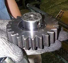
[1] Slide planetary gear No. 2 (32) and side plate No. 2 (34) from the side of planetary carrier No. 2 (31) to place in the proper location (Photo 7). [2] Insert planetary pin No. 2 (33) through the upper pin hole of planetary carrier No. 2 (31). The spring pin insertion holes on planetary pin No. 2 (33) and planetary carrier No. 2 (31) (see Step 3) must be oriented properly (Photo 8).
[3] Ensure that the spring pin insertion holes on planetary carrier No. 2 (31) and planetary pin
No. 2 (33) are aligned. Drive the spring pin 10x40 (35) with the jig (see Photo 9), monitoring the orientation (marked surface upward) and the depth (1 mm). After the pin is driven in, crimp by deforming the spring pin hole: hammer approx. 1 mm from the spring pin hole using a punch (See Photo 10). [4] Rotate planetary gear No. 2 (32) manually to check there is no engagement or rotational irregularity (See Photo 11). If found, refer to 2. Disassembling the carrier No. 2 subassembly (Page 8/10) to first disassemble, then reassemble according to the instructions in 1-2 on this page.
A new spring pin (35) must be used in reassembly. (Reusing the spring pin that has gone through disassembly may reduce the holding force which could lead to breakage.)
Repeat steps [1] through [4] above on other 4 locations to finish the procedure.
Photo 7 Photo 8

Photo 9 Photo 10 Photo 11


Swing Unit
PageNo. 3 /10 First Edition :03/2006
(3)Assembling the shaft subassembly
This section describes the assembling of subassembly through shrinkage fit. [1] Use a bearing heater and heat the roller bearing (16) (Photo 12) and the pipe spacer (19) (Photo 13) to approximately 50°C higher than the outside temperature. Since the roller bearing (16) is made of resin, use caution to avoid deforming from overheating. (The temperature must be below 120°C.) [2] Place the gear shaft (20) on a workbench. The end surface with the two tapped areas should be facing up (Photo 14). [3] Watch the upward/downward orientation and insert the pipe spacer (15) (Photo 14). [4] Remove the roller bearing (16) from the bearing heater, then insert (Photo 14).
[5] Once the temperature of the roller bearing (16) reaches the outside air temperature range, apply grease to the inside of roller bearing (16) (Photo 15). [6] Watch the upward/downward orientation and insert the bearing cover (17) (Photo 16). [7] Remove pipe spacer (19) from the bearing heater and insert observing the upward/downward orientation (Photo 16). [8] Once the temperature of the pipe spacer (19) reaches the outside air temperature range, turn over and apply grease to the inside of the roller bearing (16) (Photo 15). Add an additional mound of grease as well (Photo 17).
Photo 12 Photo 13 Photo 14


Photo 15 Photo 16 Photo 17

Swing Unit
PageNo. 4 /10 First Edition :03/2006
(4)Assembling the case subassembly
[1] Place gear case (8) upside down (with larger flange upward) on the surface plate (Photo 18). [2] Use the lifting tap holes (M16, 2 locations) on the gear shaft (20) to lift the shaft subassembly with a crane and place it into the gear case (8) (Photo 18). [3] Install the wire (18). Ensure that the shaft subassembly is installed securely. Insecure fitting may lead to dislodging of the shaft subassembly, which could cause damage to the subassembly (Photo 19).
[4] Turn over the case subassembly and place on the jig. Use caution to prevent the shaft end from hitting the ground. (It may cause the shaft to fall out.) [5] Apply liquid packing (ThreeBond 1208B)(Photo 20) to the outer circumference of the oil seal (12). Then, press fit using the jig. Apply a thin coat of lithium grease to lubricate the lip seal and press fit carefully to avoid damage to the lips (Photo 21).
[6] Watch the upward/downward orientation and insert the pipe spacer (10) (Photo 22).
Photo 18 Photo 19

Photo 20 Photo 21


Photo 22

Swing Unit
PageNo. 5 /10 First Edition :03/2006
[7] Press fit roller bearing (9) onto gear case (8) using a jig (Photo 23). [8] Punch the knock pins (7) on 4 locations (Photo 24). [9] Degrease the end surface of gear case (8) and apply a uniform coat of liquid packing (ThreeBond 1215)(Photo 24).
[10]Watch the upward/downward orientation, as well as the knock pins (7) positions, and install the ring gear (6). Fasten with 3 jig bolts (M20x200, hexagon socket head bolts) and 3 spacers (outer dia. = 27.2, inner dia. = 21.6, height = 20) (Photo 25). [11]Screw the plugs with nylon seals (11), (14) onto the drain port on the gear case (8) side (Photo 26).
Photo 23 Photo 24


Photo 25 Photo 26


Swing Unit
PageNo. 6 /10 First Edition :03/2006
2.Assembling the swing reduction gears
[1] Place the case subassembly on the jig. [2] Use the lifting taps (M10, 2 locations) on the planetary carrier No. 2 (31) to lift and place the carrier No. 2 subassembly (4) with a crane on the case subassembly (See Photo 27). Rotating the carrier a little will facilitate the assembly. [3] Insert the sun gear No. 2 (5) (Photo 28).
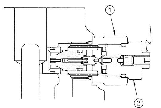
[4] Insert the thrust plate (2) into the sun gear No.2 (5) on the end surface (Photo 29). [5] Insert the carrier No. 1 subassembly (3) (Photo 30).
[6] Watch the upward/downward orientation and insert the sun gear No. 1 (1) carefully (Photo 31).
Photo 27 Photo 28


Photo 29 Photo 30


Photo 31

Swing Unit
PageNo. 7 /10 First Edition :03/2006
[7] Make sure that the distance between the end surface of the sun gear No.1 (1) and the ring gear (6) is 1.04 to 3.70 mm [i.e. (1) is lower than (6)] (Photo 32). If the distance falls short of reaching 1.04 mm: •Gear shaft (20) and the roller bearing (16) are dislocated. •The roller bearing (9) is not inserted completely. •Foreign substances are engaged.
If the distance is larger than 3.70 mm: •The wire (18) is not installed properly. •The ring gear (6) is not completely tightened into the gear case (8). •Foreign substances are engaged.
Consider the above and conduct disassembly/assembly again (Photo 32). [8] Remove the jig bolts and spacers used during the assembly of the case subassembly. Degrease the end surface of the ring gear (6) and apply a uniform coat of liquid packing (ThreeBond 1215) (Photo 33).
[9] Install the swing motor. Then degrease the thread of the hexagon socket head bolts M20x200 (23) first, and apply liquid packing (ThreeBond 1360K). Tighten 12 locations by applying the torque of 568.4 to 649.7 N.m (Photo 34 and Photo 35).
[10]Refill 5,7 liters of gear oil (Viscosity Grade: GL-4 or higher).
Photo 32 Photo 33


Photo 34 Photo 35