1 minute read
1.Circumference Filter Arrangement of Engine..................................... 1/3

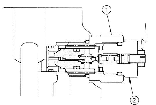
Travel Unit
PageNo. 15 /20 First Edition :03/2006
Advertisement
4. Disassembly work for each subassembly
The procedures for this chapter are basically in the opposite order of chapter 1. Assembly work for each subassembly. Refer to this chapter to carry out the disassembly work for them.
(1) Disassembly work for Travel motor subassembly
[1] Remove the O-ring by using a spatula. (Refer to the Photo 1.)
(2) Disassembly work for Shaft subassembly
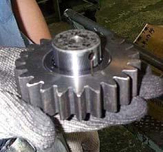
[1] Remove the snap ring (22) by using pliers. (For shaft use). (Refer to Photo 4.) [2] Remove the sun gear No.1 (21). (Refer to Photo 3.) [3] Remove the snap ring (22) by using pliers. (For shaft use). (Refer to Photo 2.)
(3) Disassembly work for Carrier No.1 subassembly
[1] Drive the spring pin 6 × 25 (39) out by inserting the spring pin driving jig into the planetary pin No.1 (36). Pay attention when driving the pin out, since the inner surface of the pin of the planetary carrier No.1 (34) may be damaged if it is driven too far. (Refer to Photo 9.) [2] Place the 1- (3) carrier No.1 subassembly on the jig in an opposite way as in Photo 7 and press out the planetary pin No.1 (36). [3] Remove the side plate No.1 (38) (2 sheets), needle bearing (37) and planetary gear No.1 (34) from the planetary pin No.1 (36). [4] Fix in a vice the planetary pin No.1 (36) and knock out the spring pin 6 × 25 (39) from the planetary pin No.1 (36) hole by using the spring pin driving jig. Take care when driving out the pin such as wrapping a protective cloth for the pin so that if planetary pin No.1 (36) may not be damaged. [5] It is necessary to use a new pin in the reassembling work. Scrap the used pins. Carry out the above procedures [1]–[5] for the 3 positions. [6] Remove the lock ring (19) by using pliers, and remove the sun gear No.2 (20) from the planetary carrier No.1 (34).