3 minute read
2.Fuel Element System Diagram........................................................... 2/3 Main Body Weight .....................................................800-3-01-00-49
Travel Unit
PageNo. 16 /20 First Edition :03/2006
Advertisement
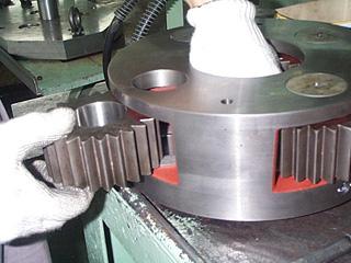
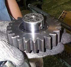
(4) Disassembly work for Carrier No.2 subassembly
[1] Drive the spring pin 8 × 45 (44) out by inserting the spring pin driving jig into the planetary pin No.2 (42). Pay attention when driving the pin out, since the inner surface of the pin of the planetary carrier No.2 (40) may be damaged if it is driven too far. (Refer to Photo 14.) [2] Remove the planetary pin No.2 (42) by hitting lightly with a plastic hammer from the hole on the under side of the planetary carrier No.2 (40). (Refer to Photo 13.) [3] Remove the side plate No.2 (43) (2 sheets), planetary gear No.2 (41) from the planetary carrier No.2 (41). (Refer to Photo 12.) [4] Fix in a vice the planetary pin No.2 (42) and knock out the spring pin 8 × 45 (44) from the planetary pin No.2 (42) hole by using the spring pin driving jig. Take care when driving out the pin such as wrapping a protective cloth for the pin so that if planetary pin No.2 (42) may not be damaged. [5] It is necessary to use a new pin in the reassembling work. Scrap the used pins. Carry out the above procedures [1]–[5] for the 4 positions. [6] Remove the trust plate No.2 (18). (Refer to Photo 11.)
(5) Disassembly work for Carrier No.3 subassembly
[1] Drive the spring pin 13 x 63 (49) out by inserting the spring pin driving jig into the planetary pin No.3 (47). Pay attention when driving the pin out, since the inner surface of the pin of the planetary carrier No.3 (45) may be damaged if it is driven too far. (Refer to Photo 16.) [2] Remove the planetary pin No.3 (47) by hitting lightly with a plastic hammer through the hole on the underside of the planetary carrier No.3 (45). [3] Remove the side plate No.3 (48) (2 sheets), planetary gear No.3 (46) from the planetary carrier No.3 (45). (Refer to Photo 12.) [4] Fix in a vice the planetary pin No.3 (47) and knock out the spring pin 13 × 63 (49) from the planetary pin No.3 (47) hole by spring pin driving jig. Take care when driving out the pin such as wrapping a protective cloth for the pin so that if planetary pin No.3 (47) may not be damaged. [5] It is necessary to use a new pin in the reassembling work. Scrap the used pins. [6] Carry out the above procedures [1]–[5] for the 5 positions.
Travel Unit
PageNo. 17 /20 First Edition :03/2006
(6) Disassembly worh for Cover subassembly
[1] Remove the trust plate No.1 (23) from the side cover (15) by using a spatula. (Refer to Photo 51.) [2] Remove the plate shim (25). (Refer to Photo 50.) [3] Remove the hexagon socket head bolts M12 × 35 (13). (Refer to Photo 20.) [4] Place the side cover (15) on the surface plate horizontally, to remove the ring gear No.1 (16) without warpage by inserting a bar into the gap between the side cover (15) and the ring gear No.1 (16). [5] The knock pin 10 × 18 (28) at the 4 positions can now be removed.
(7) Disassembly work for Case subassembly
[1] Remove all the hexagon socket head bolts M14 × 35 (2). (Refer to Photo 39.) [2] Remove the bearing retainer (8) and the plate shim (7). (Refer to Photo 38.) [3] Remove the trust plate No.2 (9). (Refer to Photo 42.) [4] Use the tap hole (M12) of the ring gear (11), and lift with a crane to take out the gear case (1). Tap the end face of the case (1) if hard to remove. [5] Remove the floating seal (33) from the gear case (1).
(8) Disassembly work for Housing subassembly
[1] Remove the floating seal (33). (Refer to Photo 31.) [2] Remove all of the hexagon socket head bolts M14 × 35 (2). (Refer to Photo 28.) [3] Remove the oil seal retainer (32). (Refer to Photo 27.) [4] Remove all of the hexagon socket head bolt M24 × 160 (31). (Refer to Photo 25.) [5] Lift up by crane the bearing housing (5) and remove the ring gear (11). (Refer to Photo 24.) [6] The ball bearing (6) can now be removed.


