4 minute read
Major Machines ・ Tools ・ Equipment Table.......................................... 2/36


Swing Unit
PageNo. 8 /12 First Edition :03/2006
Advertisement
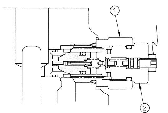
Disassembly Procedure 13 Slightly tap the valve casing side surface of the driving shaft (101) by plastic hammer and remove from the casing (301). 14 Remove the shoe plate (124) from the casing by using copper rod and tapping at housing part of the cylindrical roller bearing (443) of the casing (301). 15 Proceed with the following operation if necessary. 1.Remove the stop ring (432) and spacer (106) from the driving shaft (101) and remove the inner race of the cylindrical roller bearing by using the press.
2.Remove the oil seal (491) from the front cover (304) by the jig. Precaution Be careful not to break the sliding part of the oil seal.
When tapping the inner race of the cylindrical roller bearing by using the steel bar, tap the inner race evenly and be careful not to damage the bearing. Do not use the removed bearing again.
Do not use the removed bearing again.

3.Remove the needle roller bearing (444) from the valve casing (303) by using the sliding hammer bearing puller. Do not use the removed bearing again.
The disassembly is finished, carefully check each parts.
Swing Unit
PageNo. 9 /12 First Edition :03/2006
(4) Assembly Procedures
The assembly order is opposite with the disassembly, be careful of the following items during assembling. [1] Repair the broken part during disassembling and prepare the parts to replace. [2] Clean up each parts by washing liquid, dry them by compressed air. [3] Apply clean working oil to the sliding part, bearing and etc. [4] Replace all the O-ring, oil seal and such kind of seals. [5] Use torque wrench to tighten the installing bolts, plugs. Tighten as per the torque indicated on table 1.
The following is the assembling procedure.
Disassembly Procedure Precaution 1 Put the casing (301) on a convenient table so that the valve casing (303) side is upward. 2-1 (This item is only available during removing the cylindrical roller bearing.)
Install the stop ring (432) and the spacer (106) to the driving shaft (101), insert the annulus of the cylindrical roller bearing (443), the inner race is shrinkage-fitted.
Also insert the spacer (106), and install the stop ring (432). Be careful of the annulus direction of the cylindrical roller bearing.

2-2 Fit the inner race of the needle roller bearing (444) to the driving shaft (101), install the stop ring (433). 3 Put up the output side of the driving shaft (101) with the cylindrical roller bearing inserted and insert to the casing (301), tap the outer race slightly with the hammer by using the copper bar and install it. 4 (This item is only available during removing the orifice.)
Insert the oil seal (491) into the front cover (304) by the jig. 5 Install the O-ring (471) to the casing (301). 6 Install the front cover (304) to the casing (301) by slightly tapping with the plastic hammer.
7 Install the locking ring (437) to the casing (301) by the plier. Evenly tap the outside circle of the outer race on the joggling of the casing until completely seated.
Be careful of the direction of the oil seal. (Refer to the structure drawing.) Insert completely up to the joggling part.
Apply a little grease on the lip part of the oil seal, insert the lip without damage. (Roll the tape to the spline part of the driving shaft so that no damage to lip from spline.) Evenly tap, no damage outside the circle.
Swing Unit
PageNo. 10 /12 First Edition :03/2006
Disassembly Procedure Precaution 8 Put the casing (301) horizontally, insert the shoe plate (124).
9 Insert the push rod (116) to the cylinder (111).
Put the spherical bush (113) with the spacer
F (117) installed on the cylinder (111). Install the bigger chamfering side of the shoe plate to the casing side. To avoid dropping, apply a little grease on the matching surface. Be careful not to break the sliding part of the cylinder. (Each socket contains 2 of the push rod.)
10 Set the piston subs (121, 122) to the retainer (123). 11 Install the piston subs (121, 122) with setting of the retainer (123) to the cylinder (111). Insert into the spline of the driving shaft (101). 12 Put the casing (301) again so that the front cover (304) side is downward, install the separator plate (743) and the friction plate (742) in order to the casing (301).
Assemble three separator plates and two friction plates. Match the phases of the spherical bush and the spline so to insert easily into the driving shaft. Match the 4 gear short parts in the friction plate and combine with the same position. Match the 4 gear cut parts of the separator as per the right drawing.
13 Install the O-rings (706) (707) to the casing (301). 14 Assemble the brake piston (702) to the casing (301). Apply a little grease on O-rings to avoid broken when inserting into the brake piston. Assemble as per the 4 slits of the brake piston showing on right drawing. Match the (M8) screw to the position on right drawing. In case that the brake piston forced by O-ring, tighten the hexagon bolts M8 to the brake piston, evenly tap by the plastic hammer.

15 Assemble the brake spring (712) to the brake piston (702). Make sure the spring seating in the cobble base of the brake piston.