Control and operation
Operating manual
Operating and control elements
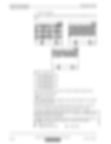
Page 3 is displayed. The screen 3 indicates for the fan pumps the amount of the momentary flow control signal.
Fig. 3-20
Electrical inputs
Press the Menu button again. Page 4 is displayed. Press the Menu button again. Page 5 is displayed. Press the Menu button again. Page 6 is displayed. Pages 4, 5 and 6 provide an overview of the status of different electrical inputs.
input has been deactivated. The status of the inputs can be changed using the menu "set data" - "set E-code".
The screen 5 indicates the status of the flow limitation. M1, M2, ... correspond to machine specific (internal) oil flow limitations. I1, I2, ... correspond to predefined oil flow limitations (see also menu "set option"). The screen 6 indicates the status other inputs. For the frequency inputs B53, the equency is recognised by the system
3 - 22
B53
Swing motor sensor
S7
Safety lever servo control
S57
Swing brake
copyright © Liebherr-Mining Equipment Colmar SAS 2020
MJFCIFSS
R 9350 E / 11695771
LEC/en/Edition: 12 / 2020
The screen 4 indicates the status of the inputs for the different movements.


