27 minute read
Control and operation


The access and the outfit of the cab
Ventilation with the air conditioner
To ventilate the cab with the evaporator in the roof of the cab:
Turn the air conditioner off with the button S2
Turn the blower fans on with the button S1
Selectthedesiredairflow withtherotaryswitchS1 andtheventsoftheevaporator.
Heater operation
Move the lever 1
The amount of water running through the heat exchanger can be regulated. Iftheregulatorispushedallthewaytotherear,themaximumamountofcoolant flows to the heater.
Set the desired air flow with the button S12
Move the lever 2
The amount of fresh air recirculated and entering the cab is regulated.
Note!
The bestheatingeffect canbereachedwhenthe air is recirculated, whichmeans, the lever 2 should be pushed all the way to the front. In this position, a small amount of outside air is mixed with the recirculating air in the cab.
To quickly defrost the windshield: Direct the warm air flow with the vents to the front. Push the sliding regulator 3 all the way to the rear. Sothemaximumairflowisblownviatheventsinthestepontothewindshield. Whenthelever3 ispushedalltheway to thefront,partofthewarm airflow isblown against the left side window.
Air conditioner operation
The cab has an air-conditioning system as standard. The air-conditioning system is used to cool and ventilate the cab.
To adjust the air conditioner fan: Use the button S1
To turn on the air conditioner compressor and the condenser fan: Use the button S2
The air conditioner can only be turned on if the evaporator fan unit is turned on via button S1.
To select the desired air flow: Use the rotary switch S1
To set the desired air temperature: Use the rotary switch S2
To adjust the direction of thecold air flow: Use the vents on the evaporator unit.
To operate the air conditioner during the summer time: Push the lever 1 all the way to the front. Turn the heaterblower off with the button S12.
To dehumidify the air in the operator’s cab: This procedure must be performed in case of very high humidity inside the cab during the colder season.
Theairconditionercanbeoperatedforashortwhilesimultaneouslywiththeheater in order to eleminate the excess of humidity and the condensation.
For best efficiency, selecta highevaporator air flow via therotary switch S1 and operate the heater with recirculated air (lever 2 all the way to the front).
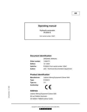
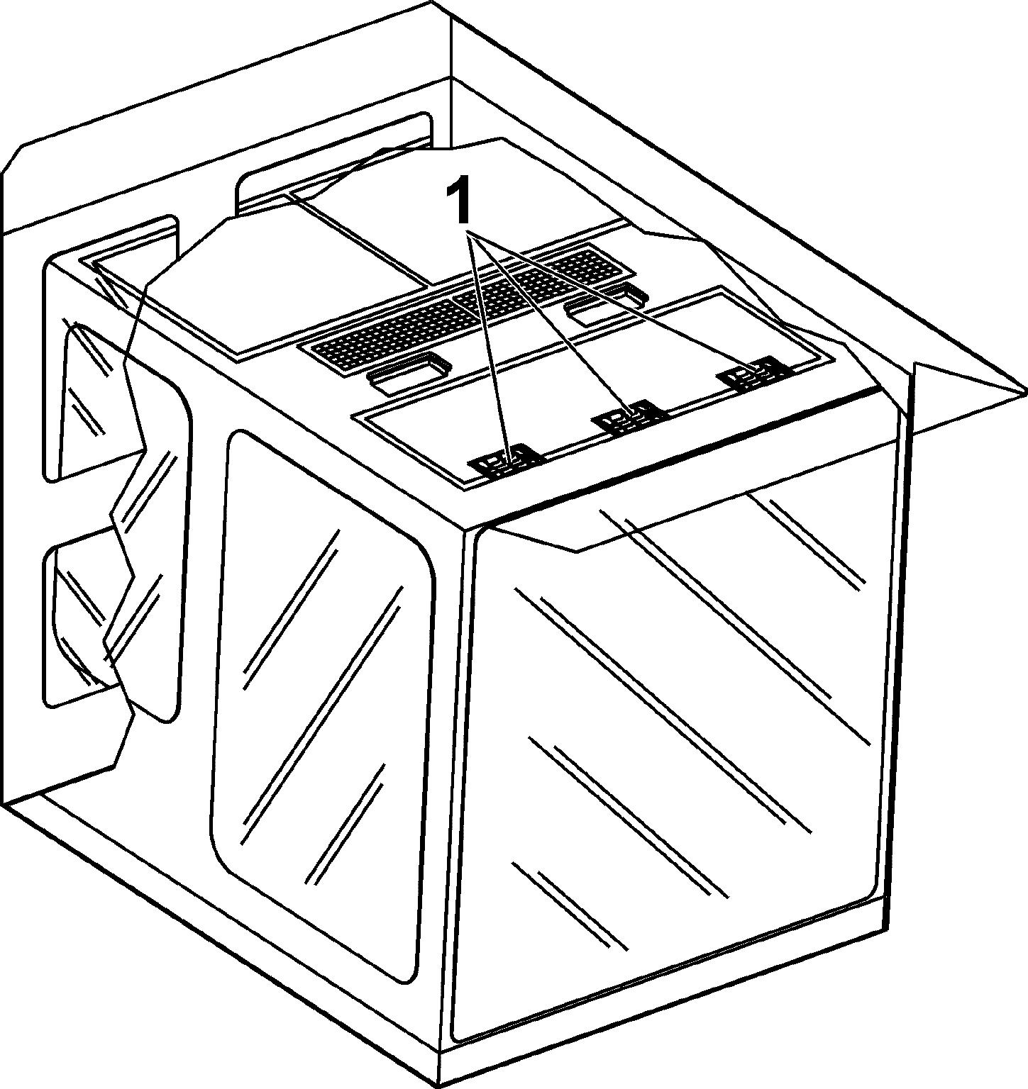
Dual air conditioning (optional equipment)
Whenyou switchthe excavatoron, the automatic dualair conditioning system is activated by default. The two air conditioning units are working alternately every 6 hours.
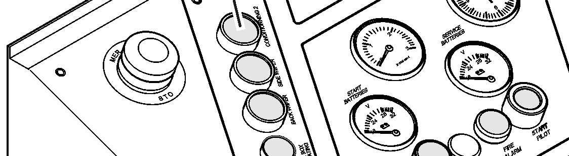
Press"Dualairconditioning"buttonS26oncontrolboard(see§"Controlboard"). Automatic air conditioning mode is deactivated. First air conditioning unit is activated. Second air conditioning unit is deactivated. Press button again.

First air conditioning unit is deactivated. Second air conditioning unit is activated. Press button again. Automatic air conditioning mode is reactivated.
3.3Setting the machine into operation
Bringing the machine safely into service und the machine each time before starting it.
area of the machine.
itate the fight against fire in case of. against unintended movement.
vicinity of the machine that it is about to start by sounding the horn.
Adjusting the operator’s standing position
controls in such a way that you are able to work comfortably and safely. must be set to the insulation position throughout operation.
Protection from vibration - seat adjusting
be adjusted depending on the weight and height of the operator.
justmentmechanismsregularlyandensure that these seat characteristics remain as per th structions.
Utilisation in confined spaces
-operatedheaters inadequately ventilated spaces. Before starting in closed areas, ensure adequate ventilation. Follow the regulations which apply for the particular area of use.
Starting the machine safely
dinstrumentsforcorrectfunction,place l and tilt the safety lever up.
regulations given in the operating instructions. st all display and checking devices. to run when there is adequate ventilation.Ifnecessary,opendoorsandwindowstoensuresufficientfreshairsupplies. make the control unit react sluggishly.
travelandswinggearbrakes,thesteeringandthesignallingandlightingdevices. Lighting devices must always be clean.
Stopping the machine safely
incline, chocks should be used to secure it from rolling away.
ispossible,aligntheuppercarriagewith the undercarriage so that the sprockets locate at the back-end. This is the only one position which enables a secured access toevery maintenance locations on the uppercarriage. able. brakes.
lever up before leaving the cab.
compartments, remove every keys and secure the machine against unpermitted use and vandalism.
3.3.1Starting / stopping the machine
General information
Note!
Whenusingthemachineataspecificheightabovesealevelandinconnectionwith certainoutsidetemperatures,theperformanceandservicelifeoftheelectricmotor is decisively affected. Undertheseconditions,thereisalsoanincreasedriskofoverheatingofthehydraulic oil.
Toavoiddamagingtheelectricmotor,themotorpowermustbereducedwhen operating in the following environmental conditions (sea level and exterior temperature): Refer to the Manual of safety, installation and maintenance of the electric motor manufacturer.
Before initial start up
Check the insulation resistance
Beforeinitial start up and after a long periodof non-use, andbeforethe excavator is connected to the power supply, check the insulation resistance:
The resistance must never be less than the minimum authorized resistance given in the instruction manual of the electric motor.
If insulation resistances should drop below the minimum values given, first verify whether the drop is from the insulators in the terminal boxes or the enclosure.
If not, the motor or the high voltage enclosure, or the slip ring must be dried with aid ofthebuiltinheaterresistors,untilthedesiredvalueisreached(seeManualforsafety, installation and maintenance).
Check direction of rotation of electric motor
Before initial operation, or before restarting the motor after repairs to the electrical system,check the directionofrotationoftheelectricmotor.Brieflystartandstopthe motor, and compare the direction of rotation to the arrows marked on the motor.
Activities before starting
Caution!
It is only possible to extinguish a source of fire when this one is accessible. Before starting, unlock all locks on the panelling of the hydraulic excavator. In the event of fire, doors can be opened immediately and the fire extinguished.
For locks arrangements, see chapter "Maintenance".
Caution!
Before starting the machine, the following activities should be carried out on a daily basis: ing air intake.
Switching on the electrical system
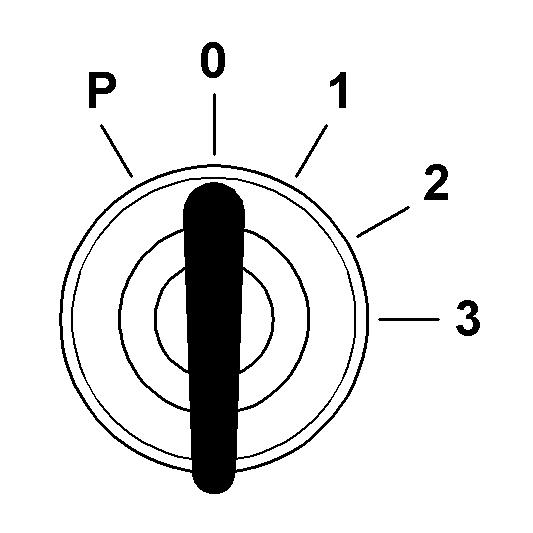
Ignition key switching positions
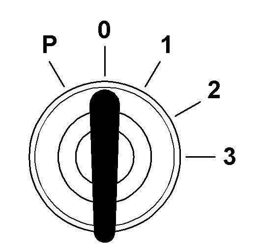
Theactivitiesreferredbelowinvolvescaldorburnhazardsduetohightemperature of the oil when the machine is at operating temperature. Please read first the chapter "Maintenance" in order to get informations about carrying out these activities. P
0
Switching on the 6kV control system
ThebatteryswitchS9_1mustbeinposition"on".Itisinstalledinanelectricalbox located on the top of the catwalk above access ladder. Turn the ignition key S1 to contact position 1
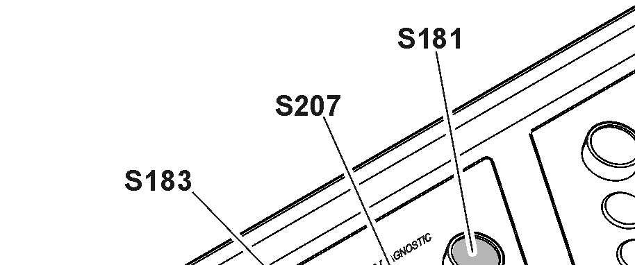
Push the button S183
The indicator light in the button comes on. Immediately after turning the system on, the display and the control unit will run through a selft test.
Make sure all indicators function properly after turning the electrical system on, i.e. thelight emitting diodes (indicator lights and gauges) turn on for ashort time thenthecompletefieldoftheLCDscreen200turnsmomentarilyblack(thematrix indicator is energised completely for a short time).
Only the LED in button S22
Note!
If no automatic check of the keyboard and monitoring display is carried out when theignitionkeyisinthecontactposition,checkthatthemainbatteriesareswitched on.
Switching on the 400V control system
Make sure the 6kV control system is switched on. Push the button S207
The indicator light in the button comes on.
Service interval display
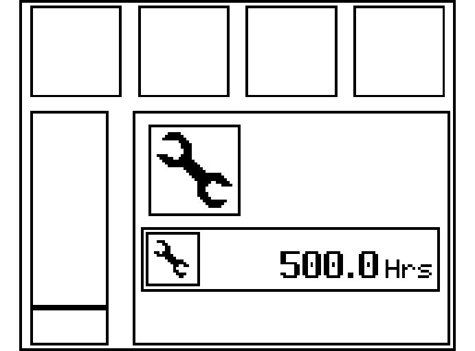
Request
After the automatic check, any service interval that may be due will be indicated by a graphic symbol.
In place of the operating hours information, the number of hours relating to the service interval required will now be displayed. The service interval request will go out after approx. 8seconds.
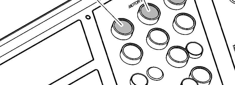
Starting the electric motor
Push the button S181.
The indicator light in the button comes on. After 8 seconds, the indicator light H110 on the control board comes on. It means that the servo oil circuit operates.
Caution!
Inordertopreventtheelectricmotorfromoverheating,motorstartingattemptsare limited foragiventimeframe.Youmustobserveasufficient timeinterval between two consecutive starting attempts.
Whenthemotoriscold,donotrestartmorethan5times.Thenwaitabout1hour before restarting.
When the motor is already warm, we recommend that you do not restart more than3times.Waitabout10minutesbetweentwoconsecutivestartingattempts.
Starting procedure when the exterior temperature is below -20°C (0.4°F)
For starting at temperatures below -20°C, it is recommended to equip the machine with a preheating system in accordance with LIEBHERR.
Warm-up procedurefor hydraulic circuit
If the excavator is started when the exterior temperature is below 0°C, the operator must do the warm-up procedure:
Make sure that the hydraulic oil temperature is sufficient (refer tolubricating sectioninchapter5)to dothisprocedure.Ifthistemperatureisnotsufficient whena preheating system is installed onthe excavator, keep preheating.
Startthemotorandletitrunwithoutloadduringthefirst3to5minutes,butatleast untilwarningsymbolsforlowhydraulictankpressurizationandforlowservopressure turn off on the LCD screen.
Caution!
Switch off the electric motor if the machine is not being used.
Step 1 - Open louvers and tarpaulins (if installed).
Step 2 - Carefully activate the working hydraulic circuits. Do not reach end positions of piston rod. Operate all movements at reduced speed: peat 10 times before moving to next cylinders: wise on approximately 1/2 turn. Repeat 4 times in each direction.
Step 3 -Repeat step 2 a second time.
Step 4 -Repeat step 2, with reaching end position of piston rod.
Step 5 -Repeat step 4 a second time.
Step6-Checkoiltemperatureinhydraulictank.Ifoiltemperatureisunder10°C, repeatstep4untiloiltemperaturereaches10°C.Ifoiltemperatureisabove10°C, move to step 7.
Step 7 - Start the travel hydraulic circuits very slowly forward and backward on approximately 10 meters. Repeat 4 times.
Aslongasthehydraulicoiltemperatureisbelowapresetvalue,thewarm-upsymbol is displayed on the SY field of the main screen. Duringthewarm-upprocedure,themainpumpsdisplacementislimitedto50%inorder to prevent damage to components.
The excavator can now be operated.
Notes after starting the motor
Caution!
Runthemotoruntilthehydraulicoilisatoperatingtemperature.Thecontrolsoperate sluggishly at low oil temperatures.
Move the machine carefully in an open space to test the function of the travel and swing brakes.
Check that the attachment is operating perfectly.
Switching off the electric motor
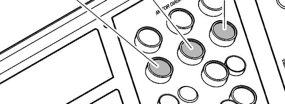
Push the button S182
The electric motor is stopped. The indicator light in the button S181 goes off.
Switching off the electrical system
Switching off the 400V control system
Push the button S208
The indicator light in the button S207 goes off.
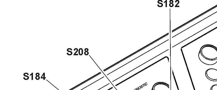
Switching off the 6kV control system
Push the button S184
The indicator light in the button S183 goes off.
3.3.2Starting aids (optional)
Functional description
Theexcavator canbefittedwithanoptionalpreheatingkit(requiredaccordingtothe ambient temperature of the work environment).
Preheating devices are installed on different components of the excavator (see § "Preheating components").
Thesedevicesaresuppliedbythefieldswitchorcanbesuppliedexternallybyagenerator set (Gen-Set).
The Gen-Set must provide at least 53kVA, 400V, 50Hz and must be connected with the connection box E1053, which isinstalled on the low voltage box S2
The preheaters are monitored and a warning light H104 on the control board will come up if a default is detected.
Preheating components
-40°C (-40°F) low temperature kit
Thiskit must beactivated every timetheexcavatorisstandingwithexternal temperature between -40°C and 0°C (-40°F and 32°F) and weekend or service and maintenance day.
The kit has following components: eaters in hydraulic tank, and valve blocks),
Optional components
Following devices can be installed in addition to the previous kits: s, lower covering, insulated PowerPack doors and fire protection sheets),
3.3.3Emergency and safety operations Emergency shutdown
Fig. 3-56 S100_1 on control board
To execute an emergency shutdown:
Turnthestarterkeytothe"0"positionorpushoneoftheemergencystopbuttons S100_1, S100_2, S100_3, S100_4 or S100_5.
This action will stop the electric motor and switch off the 6kV control system. Using the emergency stop buttons will cause the hydraulic tank to be depressurized quickly.
If an emergency stop is operated, the ladder is lowered automatically.

Caution!
Only use this shutdown method in case of emergency. Caution!
After ashutdownviaanemergencystop button,thebuttonmustbeunlockedbefore attempting to restart.
Youmustwaitatleast10minutesafteranemergencyshutdownbeforeattempting to restart.
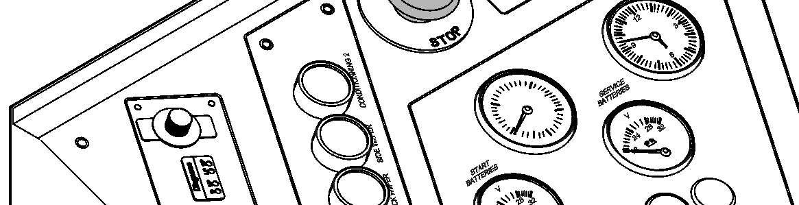
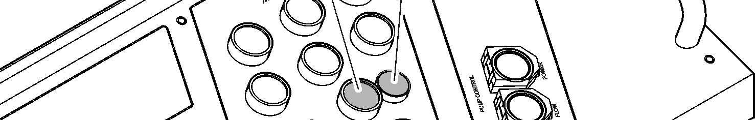
Safety controls for hydraulic pumps
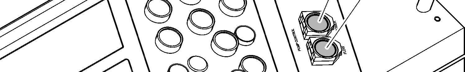
S73 Pumps power safety control
Pumps power safety control
S74 Pumps flow safety control
During normal operation of the excavator, the electronic horsepower control continuouslyadjuststhepumpflowtothepressurelevelof theworkingcircuits.Ifatrouble occurs in the circuit of the regulator, the pumps are swivelled back to minimal flow. However it remains possible in this case to carry on the working with the machine (with somewhat reduced power)by pushing the button S73
Pumps flow safety control

Duringsafetyoperation,a presetvalueforthe flowofthehydraulicpumps isactivated by pushing the button S74.

Safety controls for electric system
H114 Safety batteries

Electric system voltage monitoring
S118 Voltage monitoring relay
S185 Safety 24V
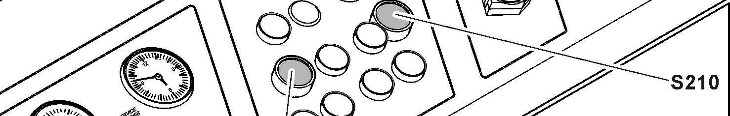
S210 Reset default end sensor S1/S2
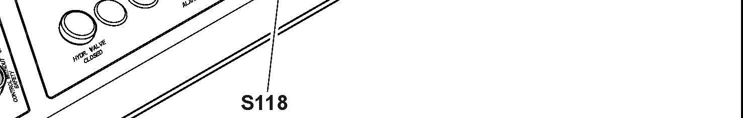

The excavator has an overvoltage and undervoltage protection. If an overvoltage or undervoltage is detected in the electric circuit: The electric motor is stopped. The indicator light in the button S118 comes on.
Push the button S118 to acknowledge the information.
Battery power supply
If the power supply from theelectric plant stops, you can switch to the battery of the excavator to supply the service system and to lower the attachment if necessary.
Push the button S185.
Power supply is switch to the battery. The indicator light H114 comes on.
S1 and S2 doors protection
The excavator has protection on high voltage box S1 and low voltage box S2

Setting the machine into operation
If the door on S1 or S2 is open: The electric motor is stopped. The indicator light in the button S210 comes on. Push the button S210 to acknowledge the information.
Tow the machine
It is not permitted to tow the machine.
If you must move orrecover a defective or unserviceable machine, contact Liebherr customer service.
3.3.4Driving
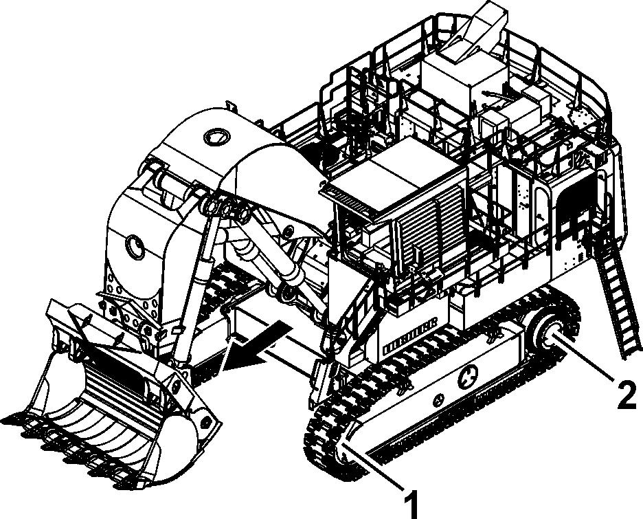
Driving straight ahead
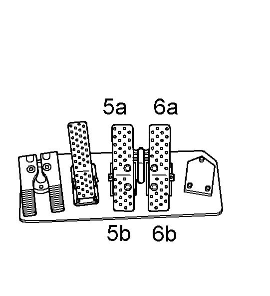
1 Idler 5a / 5b Pedal for left drive unit
2 Sprocket wheel 6a / 6b Pedal for right drive unit
Caution!
Whendriving,theuppercarriagemustberotatedtotheundercarriageinsuchaway that when drivingforwards, the idler 1is infront and the sprocket wheel 2 is at the rear.
Driving forwards:
Push both pedals forward (5a and 6a).
Reversing: copyright © Liebherr-Mining Equipment Colmar SAS 2020
Caution!
Before reversing, ensure that the area behind you can be safely entered.
Push both pedals down (5b and 6b).
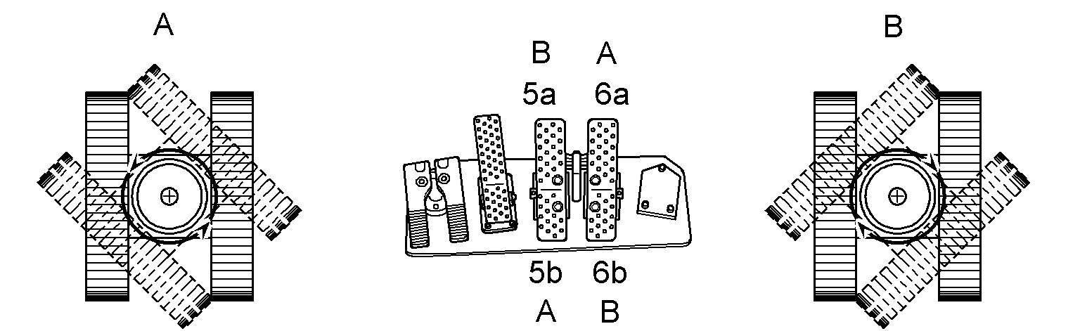
Turning on the spot
3-60 Turning on the spot
Turning left (A): Push the left pedal down (5b). Push the right pedal forwards at the same time (6a).
Turning right (B): Push the right pedal down (6b). Push the left pedal forwards at the same time (5a).
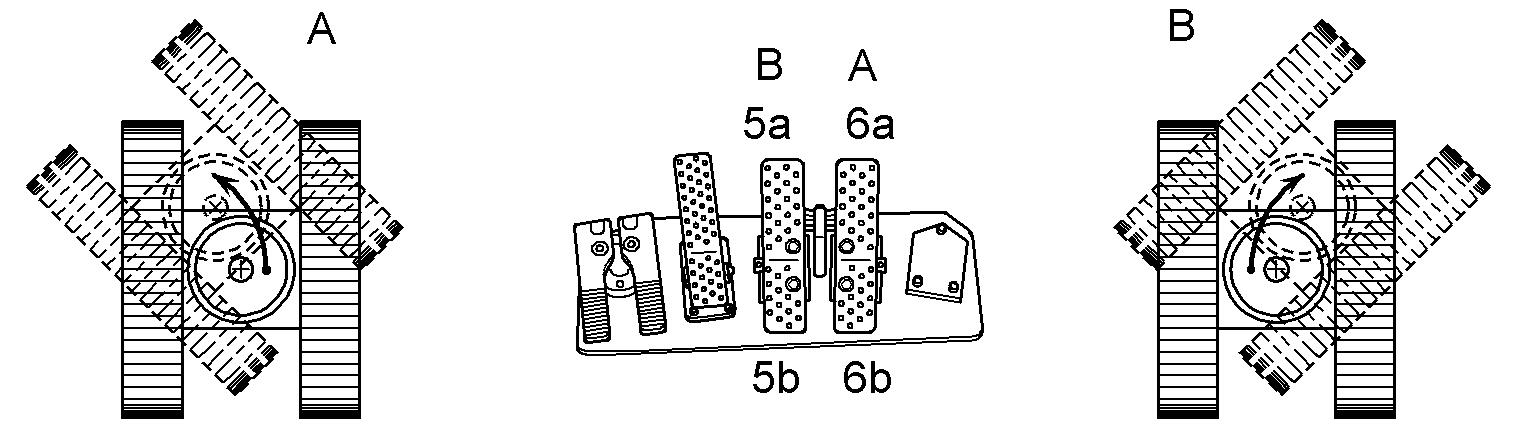
Turning with a crawler
Turning with a crawler
Turning to the left (A): Push the right pedal forwards (6a).
Turning to the right(B): Push the left pedal forwards (5a).
Note!
If possible, avoid turning backwards in order to preserve the running gear parts.
Manual control of the travelling movements
When particularly careful and progressive travel movements are required: Insert the hand levers (1 and 2) delivered in the tool box of the machine into the both pedals for travel movements. The travel movements can now be controlled manually.
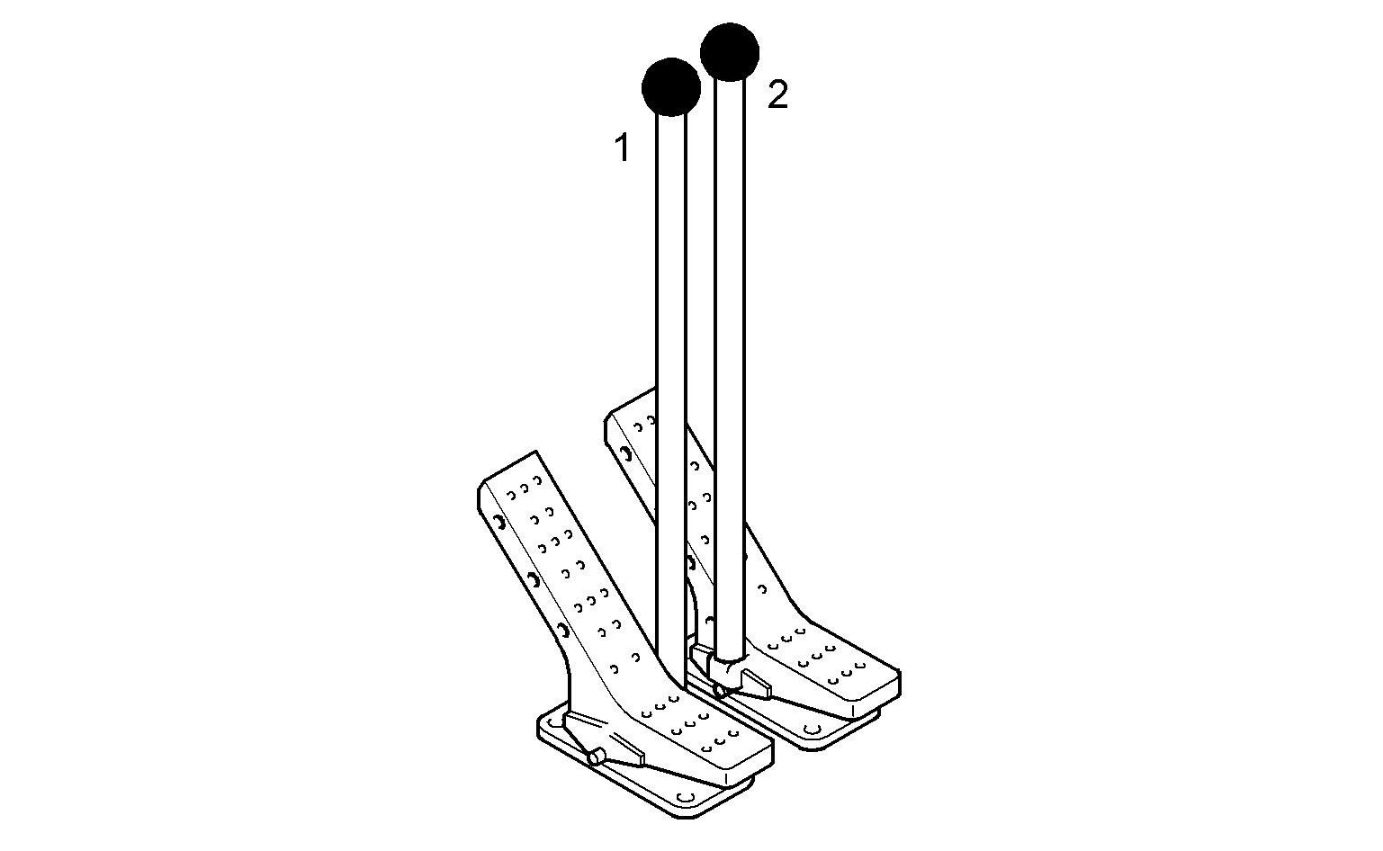
Note!
When travelling the machine onto or off a low loaded, the travel movements must be controlled manually for safety reasons.
Controlling the speed
ThedrivingspeedisinfluencedbybuttonS21.Thetravelmotorscanbeoperatedin two different positions:
Normal drive (position 1):
Maximum tensile force of both drive units at moderate speed. Fast drive (position 2):
Reduced tensile force of both drive unitsat maximum speed.
Press switch S21
Transfer from normal drive to fast drive is activated. LED 1 in the button illuminates.
Whiledriving,themachinewillautomaticallyswitchfromnormaldrivetofastdriveas thegroundconditionspermit.Aftertransferringtofastdrive,LED 2illuminates.Ifthe ground conditions become more difficult again, the system will automatically switch from fast drive to normal drive. LED 1 illuminates.
Press button S21
Transfer from normal drive to fast drive is deactivated. LED 1 in the button goes out.
When button S21 is switched off, the travel motors remain continually in position 1.
Braking the machine
The hydrostatic travelling mechanism of the machine also functions as a service brake.
Disengage the pedals for the drive units. The pedals will return to the neutral position. The travelling mechanism will be stopped. The machine will be braked.
When the pedals for the drive units are in the neutral position, the hydrostatic drive prevents the machine from rolling off.
Intheneutralposition,theparkingbrakewillbeappliedautomaticallyafterafewseconds. The work equipment can, however, still be moved.
Actuating a travel pedal again will disable the travel brake.
Caution!
Disengaging the pedals quickly causes the machine to halt abruptly. Before starting the machine, always fasten the safety belt.
Cable reel (optional equipment)
The cable reel winds and unwinds automatically the supply cable.
H140 The cable reel is at the end
H141 The cable reel is near the end
H142 Cable reel failure
Ifthecablereelisneartheend,thewarninglightH141comesonandthebuzzerop- erates for 1 second. copyright © Liebherr-Mining Equipment Colmar SAS 2020
Caution!
Risk of damage to the machine.
If the cable reel is at the end, the warning light H140 comes on and the buzzer operates for 1 second.
Do not travel more in direction of the end.
Caution!
Risk of damage to the machine.
If there is a cable reel failure, the warning light H142 comes on and the buzzer operates for 5 seconds.
Stop the machine immediately and tell the maintenance personnel.
Caution!
Risk of damage to the machine.
Make sure that the angle A between the undercarriage and the supply cable is never more than 45°.
3.4Working with the machine
Working safely with the machine
withthespecialfeaturesofthejobsite andanyspecialprecautionsandwarningsignals.Examplesofparticularworkenvironments would be on-site or traffic obstructions, the load-carrying capacity of the ground and any requirements to make the job site safe from public use.
ground.
reduced visibility and changeable ground conditions.
power and gas lines on the job site and takeparticularcarewhenworkingnearthem.Ifnecessary,informtheresponsible authorities.
laws, regulations and rules applicable at the place of use.
aerial lines. Do not allow the attachment to come near cables when working near electrical aerial lines. Risk of fatality! Inform yourself about required safety distances.
theeventofanytransferofelectricity:
•warn anypersonnel inthevicinitynottocomecloseto theexcavatorand not to touch it, the danger zone to a sufficient distance, solutely sure that voltage in the line, which had been touched or damaged, has been turned off! cured. lationsandifnecessary,ensurethatthemachinehasbeenmadesafeasperregulations beforehand. ions of poor visibility or darkness. h the safety belt securely fastened (if available). mediately. stthebrakesysteminaccordancewiththeregulations given in the operating instructions. while the machine is moving. doperatedinsuchawaythatitisstable and that there is no danger of overturning. Only known loads may be moved with the attachment; this applies particularly when using the grab. ngitudinal direction when moving and hold the load as close to the ground as possible. start to tip or slide sideways, however, turn the upper structure to face downhill and lower the attachment at the same time. uphill and not side on to the slope. or you could lose control of the machine. dieselenginemustrunatmaximalspeedandthespeedmayonlybereducedusing the foot pedals. to protect the truck operator. ationsetc.,alwaysuseprotectivedevices specifically designed for the purpose. overview of and whenever necessary, ask for the assistance of a spotter. Only permit one person to give you signals. machine operator. This people must be in with him. combination,thereisariskofcollisionbetweenthe work tool and the machine (uppercarriage and undercarriage). The greatest degree of care must be taken to avoid damage. combination,thereisariskofcollisionbetweenthe worktool andthecab,thecabprotectionor theboom cylinders.Thegreatestdegreeof caremustbe taken toavoiddamage when thehoeteethcomewithinthis area. combination,thereisariskofcollisionbetweenthe worktoolandtheattachmentparts.Thegreatestdegreeofcaremustbetakento avoid damage. combination,thereisariskofcollisionbetweenthe liftringof theattachment and thecaborthecabprotection.Beforeoperating,ensure that there is no risk of collision, especially on excavator with cab elevation. If necessary remove the lift ring. the soil. a ditch without striking the attachment on the ditch walls. tachment has been swung into a wall or any other obstacles. tracted are not permitted, even when working in alongitudinal direction. machine components. plications are required. withsidecutters or that areduringoperations with rocky material. This would prolong the work cycles and may lead to damage to the bucket as well as further machine components. et position may only be employed if the working tool or the attachment does not touch the material. drill into the material is not permitted. slowly back to the ground. hydraulics. This would damage the machine. forbiddentoraisethemachinewiththe dozing blade (e.g. carving at the ceiling when tunnelling). ground collapse under the machine. inthefollowing Miningapplications is not approved or condoned by Liebherr: Scaling), without exception. hing or Double flitching) when the material is un-blasted and non-fragmented material which requires the boom down (rod side) pressure to exceed 50 bar.
EXCEPTION: excavators used for loading and unloading, see the part "Safe use when loading and unloading (particularly when loading and unloading wood)" on page73.
Otherwise, you must stop the excavator, turn off the radio and keep inside the closed cab until the end of the storm. functions. Always check their functions when starting up the machine.
The use of these Mining methods will result in increased fatigue levels to steel structures and components of the respective Liebherr Mining Machine and thereforewillsignificantlyreducetheexpectedlifetimeofstructuresand/orcomponents.
Working safely with the machine used for demolition application
n application are subject to specific conditions and mustbefittedwithspecialsafetydevices(forfurtherinformation,contactLiebherr customer service).
application,youmustalsoobeytheadditional safety instructions that follow.
Before the operation of the machine
ions are in the specified limits.
l safetydevices necessary for the taskoperatecorrectly.
le local regulations.
Incorrect
Use Of The Machine Used For Demolition
application carried out only by trained specialist personnel.
or special tool you use.
andapprovedoperatorprotectivestructures (e.g. FOPS, front protective grid) are not installed.
Do not stop it suddenly. Always move the attachment or special tool slowly and with constant speed movements.
ffects on the machine stability, reduce the height and the speed of the movement.
e attachment or special tool.
the back-end.
safely positioned on the ground.
y and the acoustic warning signals.
percarriage turns.
Incorrect use of the attachment or special tool used for demolition application specialtoolexclusivelydesignedforthe task. ltoolwith closedwindshieldandwitha front protective grid. its specifiedlimits.For moreinformation, nual of the tool manufacturer.
Safe use of a hydraulic hammer or a hydraulicripper ion, the use of a hydraulic hammer or a hydraulicrippercan resultinvibrations,shocksorstresses whicharehigherthan in normal use. It may reduce the expected lifetime of structures and/or components. ripper must be selected with particular care.WhenusingahydraulichammerorahydraulicrippernotpermittedbyLiebherr, warranty for steel structures and machine components will be ceased. stone, concrete and other breakable materials. draulic ripper in the longitudinal direction of the machine and with the windshield closed or with a front protective copyright © Liebherr-Mining Equipment Colmar SAS 2020 grid. that nocylinderisentirelyextendedor retracted and that the stick is not in the vertical position. performing retraction and extension motions of the hydraulic hammer. time tothesameplace. Changethe breaking point. Too longuninterruptedoperationofthehydraulichammerleadstoanunnecessaryoverheatingofthehydraulic oil. lic hammer or of the hydraulic ripper to breakstoneorothermaterials.Donotmoveobstacleswiththehydraulichammer. Misuse of this nature would damage both the hammer and the machine. essure of the dampening accumulator of the hydraulicrippermust be adjusteddepending onthenature of theground and the excavator model.
Safe use of a ripper
where the use of a bucket is not efficienttobreakoutrocks.Thus,theseapplicationsaremoreseverethaninnormal use.
n,theuseof arippercanresultinvibrations, shocks or stresses which are higher than in normal use. It may reduce the expected lifetime of structures and/or components.
. Contact the Liebherr customer service.
ted by Liebherr, warranty for steel structures and machine components will be ceased.
n the machine on firm and level ground.
Safe use when loading and unloading (particularly when loading and unloading wood)
attachment raised and the load lifted up; this applies, for example, when loading and unloading wood.
inewillbedisplacedupwardsinthevertical direction. The driving characteristics of the machine will thus be influenced persistently, e.g. through reduction of the dynamic stability. The following instructions are therefore to be observed at all times: mental conditions.
noeuvres. rection.
ed the upper structure to the driving position. nging movement and dropping of the load when the attachment is raised. cab. there is a risk of objects falling from above. such as logs, is dependent on length, diameterand specificweight.Theinfluencingvariablespresent inanatural product, such as moisture, must be noted. with grabs require the machine operator to receive special instruction and training. sufficient training and practical experience.
Safe use of machines with tower elevation
gravity of the machine will be displaced upwards in the vertical direction. The driving and work characteristics of the machine will thus be influenced persistently, e.g. through reduction of the dynamic stability.
themachinemustbealignedhorizontally before use. In horizontal alignment, the centre of gravity of the uppercarriage is over the centre of the undercarriage, which reduces the risk of tilting.
tilt despite being aligned!
The following instructions are therefore to be observed at all times: noeuvres. aking, accelerating and changing direction. ly be approachedinthelongitudinal direction in order to prevent unacceptable banking of the machine. slowly!
When moving the machine: holes and uneven surfaces jeopardize the stability of the machine. red machine characteristics (high centre of gravity) and environmental conditions.
When loading and unloading: the uppercarriage out of the transport position. capacity of the substrate). A support subsiding would have disastrous consequences! s with increased care. as close as possible to the machine (Caution! swinging grab) and hold the load close to the undercarriage and above the substrate.
Protection from vibration
building machinery are mainly the result of the type andmethodofuse.Thefollowingparametersinparticulararedecisiveinfluences: ng, brakes, contro control elements when driving and working. determinesthevibrationalloadssincehe selects the speed, gearbox ratio, working method and route himself. This means that there is a wide range of different vibrational loads for the same machine type.
Whole-bodyvibrationalloadforthemachineoperatorcanbereducedifthefollowing recommendations are observed: attachment parts andauxiliary devices for eachpart of the job. hydraulic excavators, this should be a seat which corresponds with EN ISO 7096). be adjusted depending on the weight and height of the operator. justmentmechanismsregularlyandensure that these seat characteristics remain as per th structions. ine, particularly with respect to: tyre pressure, brakes, steering, mechanical connections etc. ment jerkily. working and driving in good condition: calculate in sufficient time to carry out any work required. ble) which reduce vibration for machines that are driven frequently. If such auxiliary systems are not available, regulate speed to avoid "oscillating" the machine.
3.4.1Uppercarriage swing movements
The swing movements of the uppercarriage are controlled by the left joystick.
Fig. 3-65 Rotating the uppercarriage
Push the left joystick to the left c: The uppercarriage rotates to the left. Push the joystick to the right d: The uppercarriage rotates to the right.

Braking the uppercarriage
Themachineisequippedaswellwithanhydraulicaswithamechanicalswingbrake.
The hydraulic swing brake
Let the left joystick move back to neutral position. The hydraulically swing braking of the uppercarriage takes place. In normal working conditions, the braking efficiency is sufficient to bring the uppercarriage to a standstill rapidly.
Move the left joystick in the opposite direction. The maximum hydraulic braking actionof the uppercarriage is achieved.
The mechanical swing brake
Themechanicalbrakeisanegativelyactingmultidiscbrakewhichisintegratedinthe swing gear. It allows to stop the uppercarriage in any desired position (for parking, when working on a slope, ...)
Press "Swing brake" button S17 Swing brake is applied. LED in the button illuminates.
Press button again. Swing brake is released. LED in the button goes out.
Caution!
Thebrakeonlyapplieswhentheuppercarriageisnearstandstillandifnoswingmotion is actuated with the joystick.
To stop the uppercarriage when working on a slope: Use the joystick to reduce the uppercarriage speed. Press button S17 to operate the swing brake.
Move the joystick back to "0" position only after the brake operates.
To check the mechanical swing gear brake: When the uppercarriage is stationary.
Press button S17 to apply the mechanical swing brake. Push the left joystick to the right and then to the left as far as the stop. If the swing brake function is OK, the uppercarriage does not start swinging.
Semi-automatic swing brake control (optional equipment)
Press button S17 to release the swing brake. LED in the button goes out.
The swing gear brake is in mode semi-automatic and can now be controlled as follows by the rocker switch S57:
Tilt down the rocker switch S57 on the joystick handle.
Thebrakeisappliedwhentheuppercarriageisatstandstill,respectivelyitapplies as soon as the uppercarriage speed gets lower than a limit value.
Tilt up the rocker switch S57. The brake remains released permanently.
Note!
TheredLEDbesidethebuttonS17islightinginanycasewhenthebrakeisapplied. If this light does not go out when the rocker switch S57 is tilted up, the button S17 must first be pushed to pre-select the semi-automatic mode.
Caution!
Thebrakeonlyapplieswhentheuppercarriageisnearstandstillandifnoswingmotion is actuated with the joystick.
To stop the uppercarriage when working on a slope:
Tilt down the rocker switch S57
Use the joystick to reduce the uppercarriage speed. Move the joystick back to "0" position only after the brake operates.
Emergency stop of the uppercarriageswing motion
The swing brakecan beappliedindependently oftheuppercarriage RPM by switching the "Swing brake" button S17 to position "applied".
Caution!
Perform this brakingvia "Swingbrake" button S17 only exceptionally, i. e. in emergency cases, since it causes fast abrasion of the brake discs.
3.4.2Working position
Fig.
Working position – machine

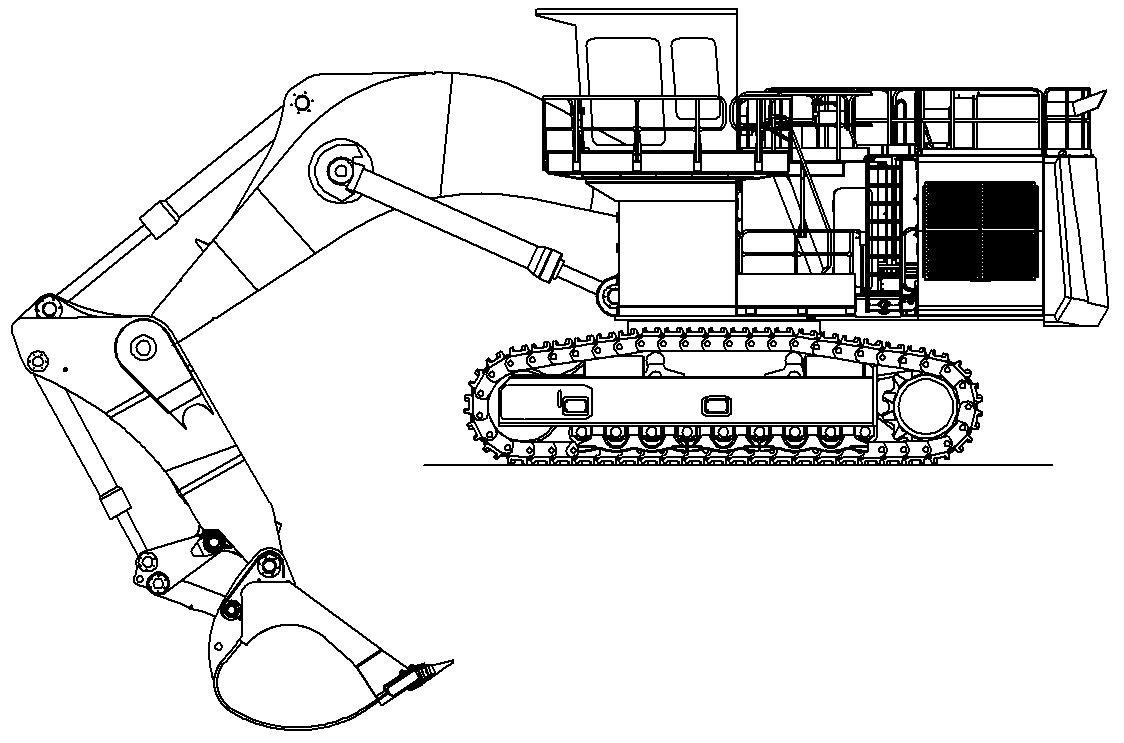
Work with the machine is generally to be carried out over the idler.
Note
Drive backwards when you are working lengthwise with the backhoe bucket.
3.4.3Joystick functions when setting up the machine Operating the stick cylinder
The stick cylinder is operated using the left joystick 4
Push the joystick back a Stick will be drawn in.
Push the joystick forwards b Stick will be extended.
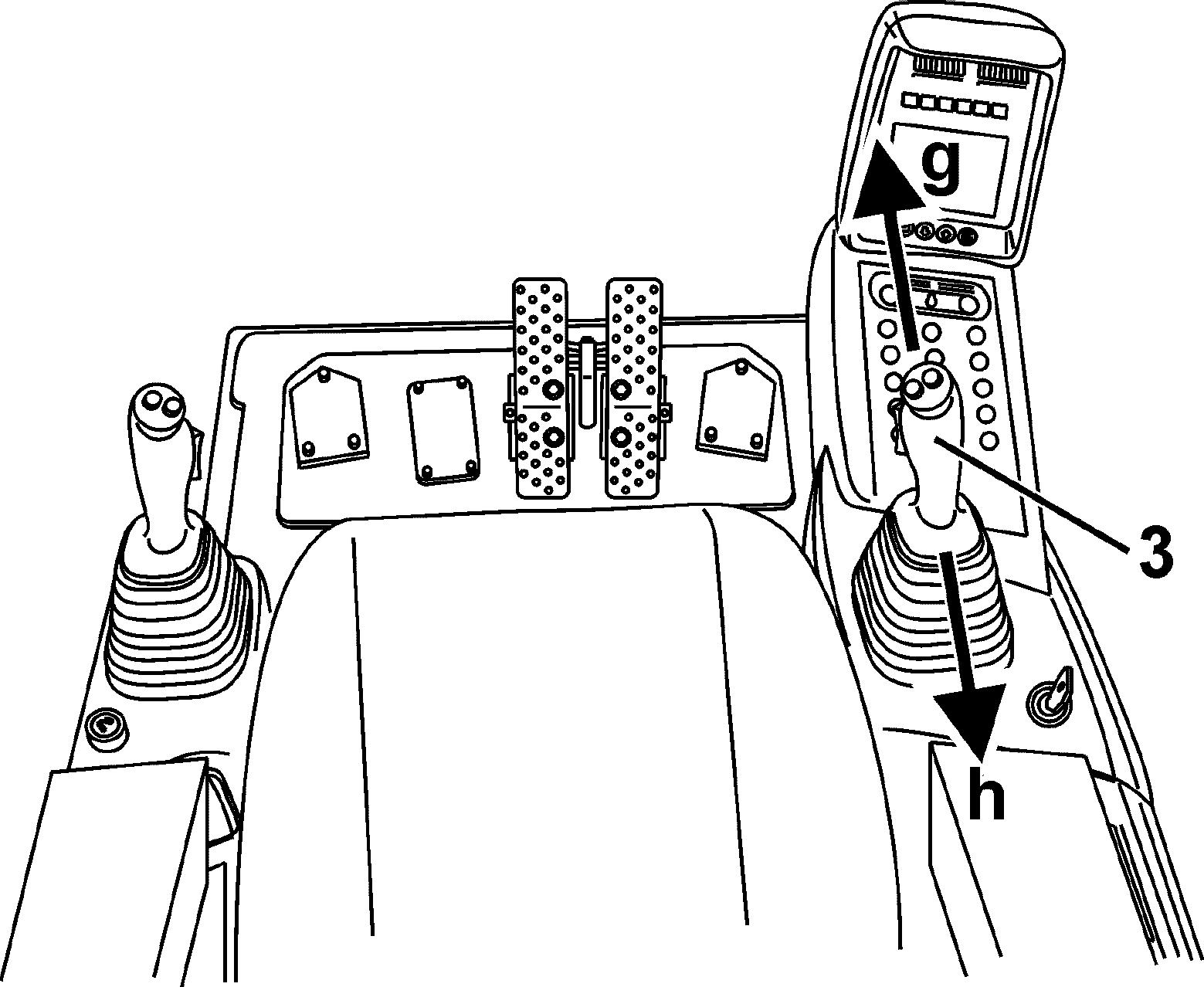
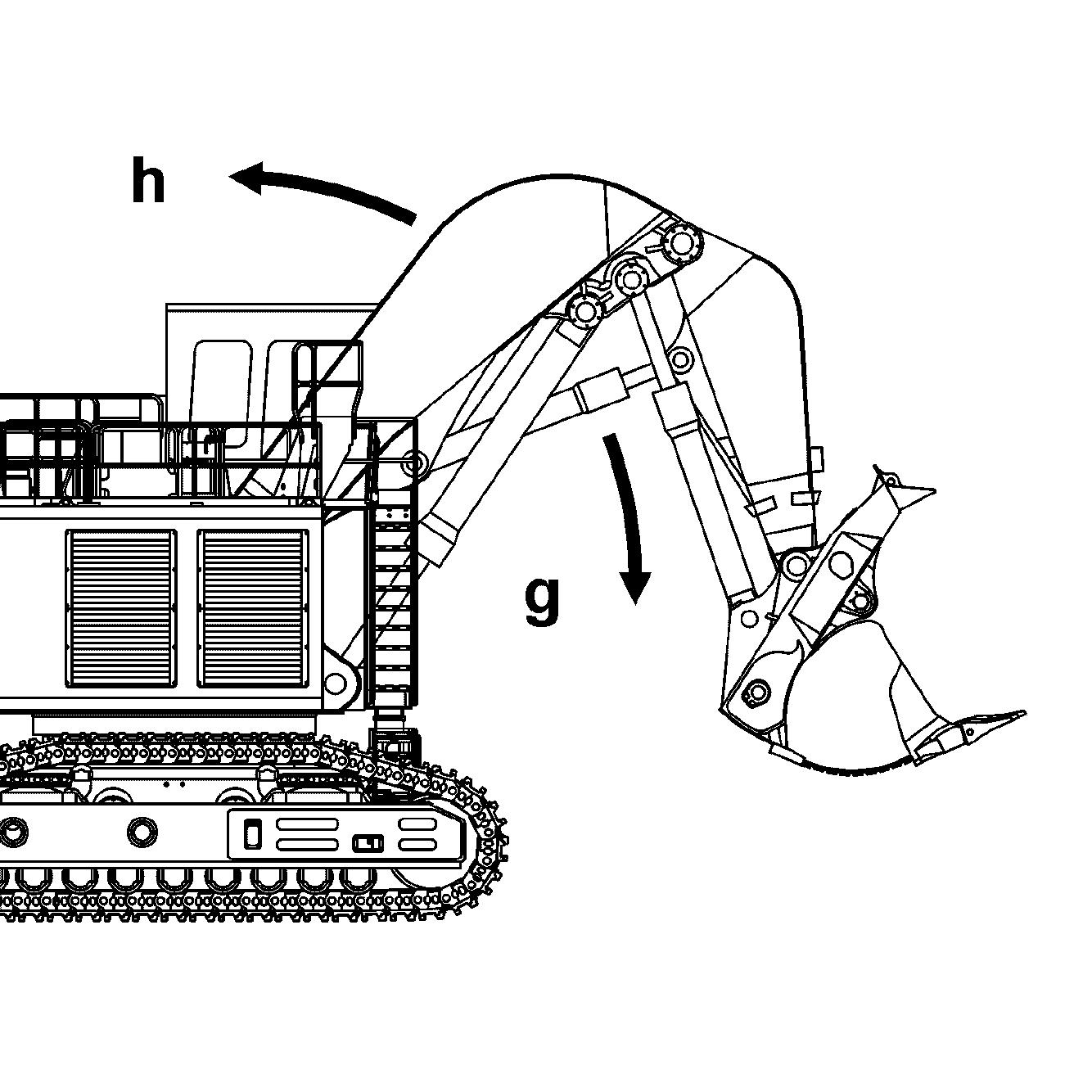
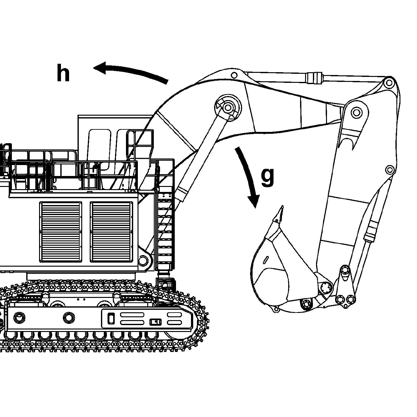
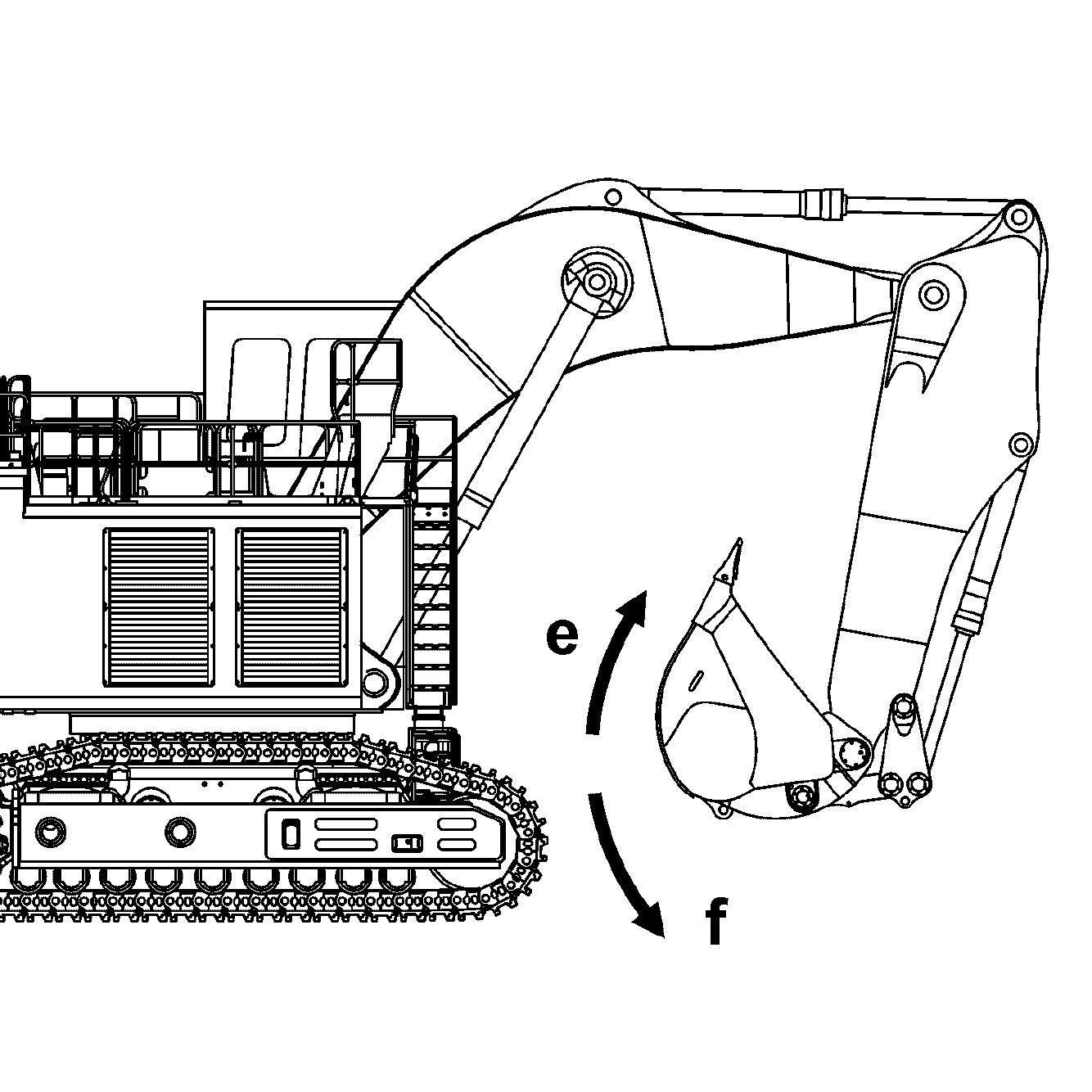
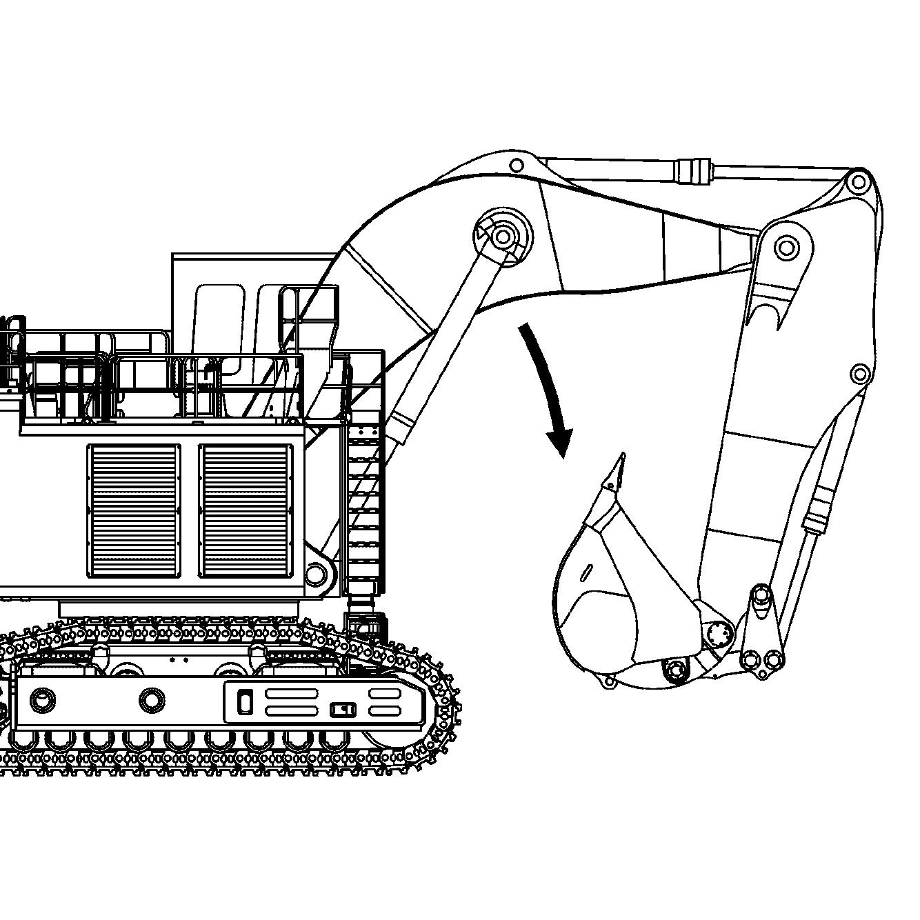
Operating the boom cylinder
The boom cylinder is operated using the right joystick 3
Push the joystick back h Equipment will be raised. Push the joystick forwards g Equipment will be lowered.
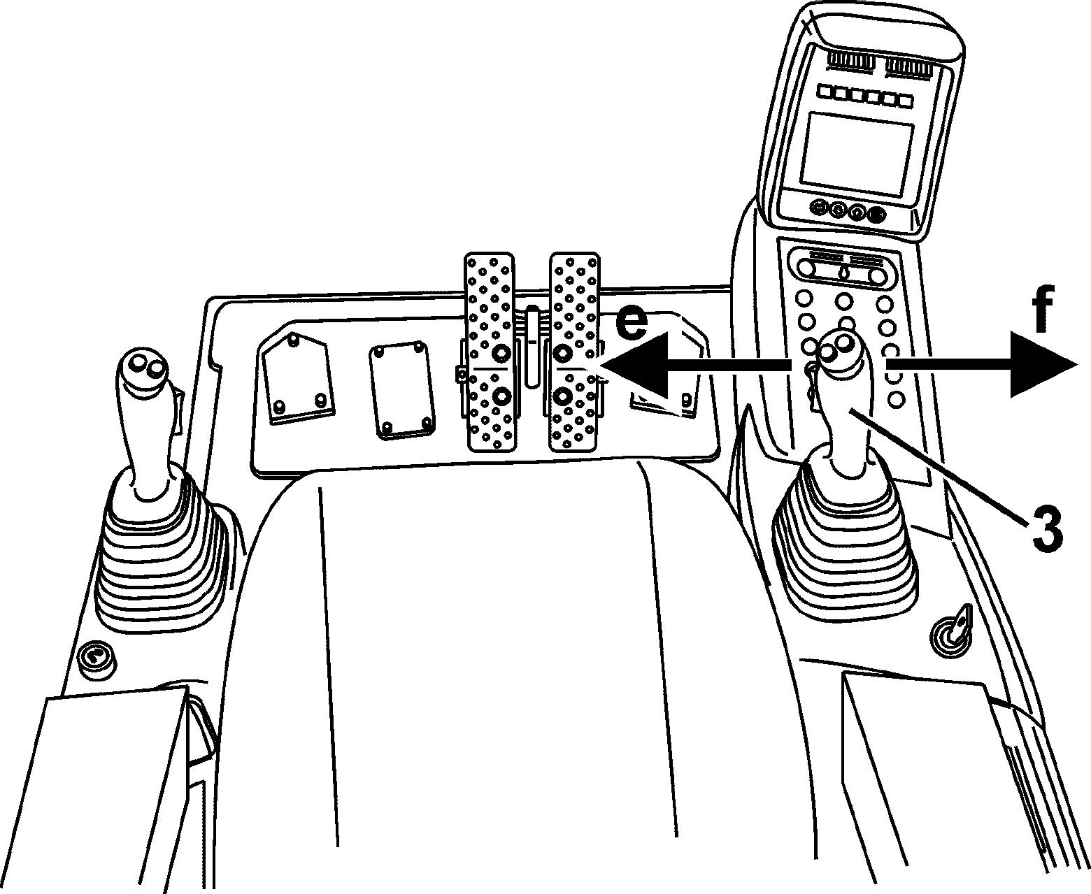
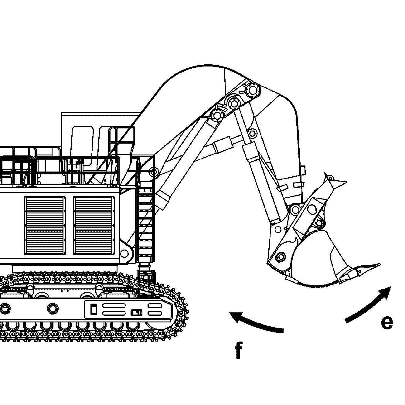
Operating the bucket
The bucket cylinder is operated using the right joystick 3.
Push the joystick to the left e Bucket will be tilted inwards. Push the joystick to the right f Bucket will be tilted outwards.
Operating the bottom dump shovel bucket
The bottom dump shovel bucket is moved via two pedals, 7a and 7b.
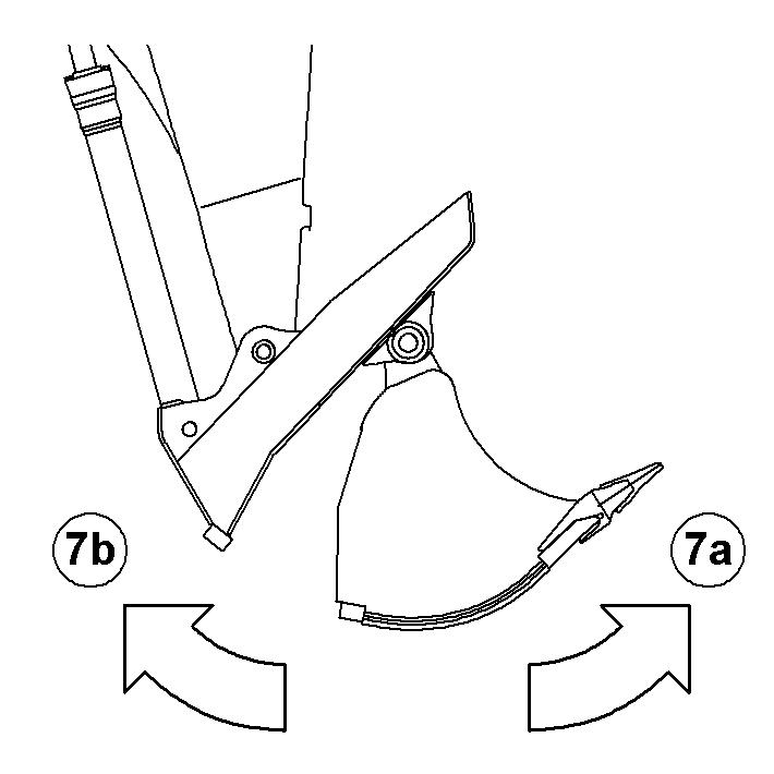
Push pedal 7a. Shovel bucket will be opened. Push pedal 7b Shovel bucket will be closed.
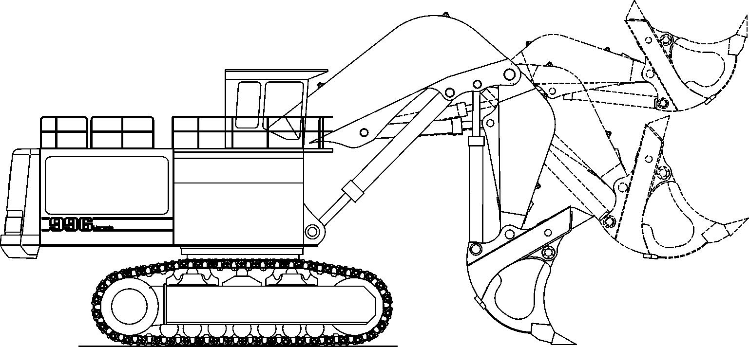
Floatpositionofboomcylinderforbucketoperation(optional equipment)
To turn on the float position for the lift cylinders, Move the right joystick 3 forward, Push the button S5 on top of the handle at the same time.
Now the bucket can be used for grabing work while moving the joystick 4 forward to extend the crowd cylinders.
Theattachmentcanthenmovefreelyupordowndependingongradeandthebucket will automatically follow the ground contour.
Combined movements
Movingajoystickdiagonallyresultsintheworkfunctionsconcernedbeingcombined. This allows different equipment movements to be activated at the same time. The operator can do the following movements without any additional manipulations. When the swing movement is actuated, all working functions / movements are possible without affecting the swing movement.
Duringtravel,everyattachment movementis possible,butthe swingmovementhas priority. In this case, the travel movement is reduced.
3.4.4Loweringtheworkequipmentwhenthemotorisnotrunning
In an emergency, the equipment can be lowered when the electric motor is not running.
Fig. 3-72 Lowering the equipment when motor is not running
Turn the ignition key to contact position 1
Operate the joystick or the foot pedals until the equipment has lowered.
Note
Thisreserveislimitedandisonlysufficientforsmallmovementsofthepilotcontrol devices.
Only operate the joystick in the directions for lowering the equipment.
3.5General working methods
3.5.1Minimum impact working methods for your machine
Toincreasetheservicelife of the machine and avoid unnecessary damage and the resulting repairs, please note the following points: stopping the equipment on the walls of the ditch. materialtoberemoved,inthelongitudinaldirectiontoo,isnotpermitted.Repeatedly hitting the work equipment against rock or other hard material will damage steel parts and machine components. ofboom,stickandworktool,theworktool couldhitor break through into the cab. This could operator. in rocky material. This will extend the work cycles and could result in damage to the bucket and other machine components. l partner if special teeth are required for heavy or special applications. thisshouldoccur,slowlylowerthemachine to the ground. Do not permit the machine to lower quickly and do not intercept thefalling movement using the hydraulics,sincethis could result indamage to the machine.
3.5.2Preparatory activities
Danger!
Risk of fatal injury and damage to the machine when working. erating instructions.
Position the machine so that the load material can be taken up above the idler.

Danger!
Insufficient support and machine damage.
Danger!
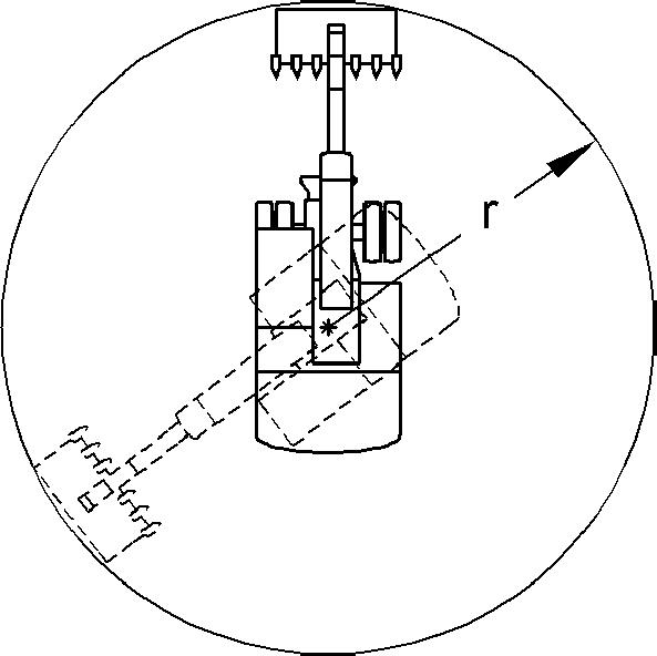
Risk of fatal injury due to rotating the machine. Ensure that nobody stands within the hazard area r of the machine.
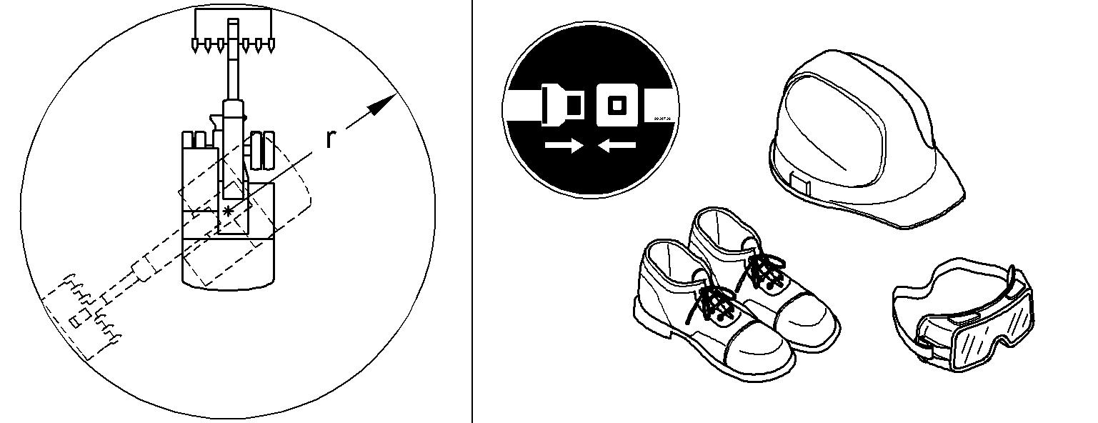
Caution!
Risk of injury when working.
Always wear safety shoes and, particularly when leaving the cab when demolition work is going on, a protective helmet and safety glasses.
Always wear the seat belt.
Use the horn to give a short warning signal before starting work.
3.5.3Positioning of the machine
Settingupproperlyisapre-requisitetosafeefficientloading,andhelpsmaintainstability,power andbenchlevels.It will alsoreduceoperator fatigue.Positiontheexcavator as close to the working face as safety permits.
Caution!
Always ensure there is sufficient clearance between the counterweight and the face, including allowing for any rocks or material that may fall down.
Fig. 3-75 Recommended digging
The recommended digging range is about a 90° arc in front of the machine (A).
Note!
Avoid digging at right angles to the tracks.
3.5.4Working with thebackhoe bucket
Danger!
Risk of fatal injury and damage to the machine when moving the backhoe bucket. Ensure that the backhoe bucket is not slewed too close to the cab.
tor.
Ensure that nobody is standing within the hazard area of the backhoe bucket.
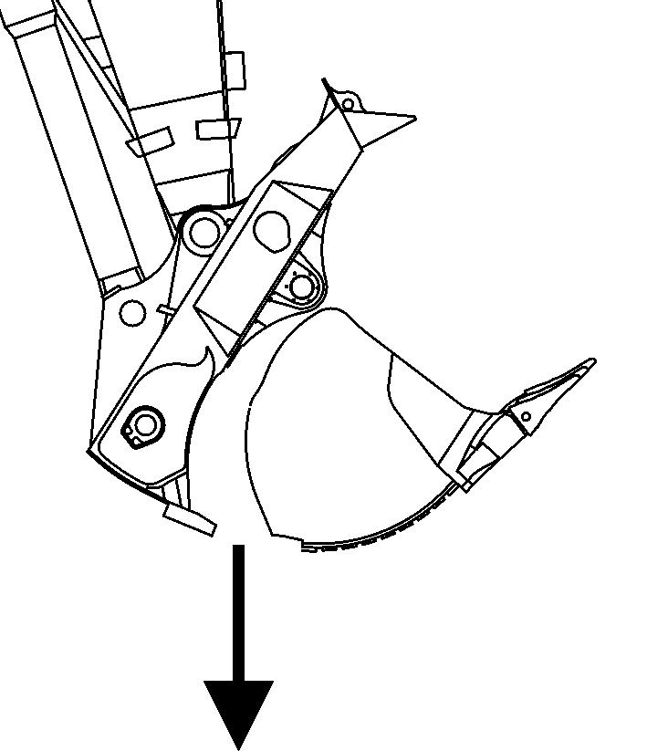
Digging
Aligntheshovelarminsuchawaythatitsundersideisatanangleofapprox.30° forward to the vertical.
Align the backhoe bucket in such a way that its underside can enter the ground at an angle with the axle of the shovel arm between 10° and 20°.
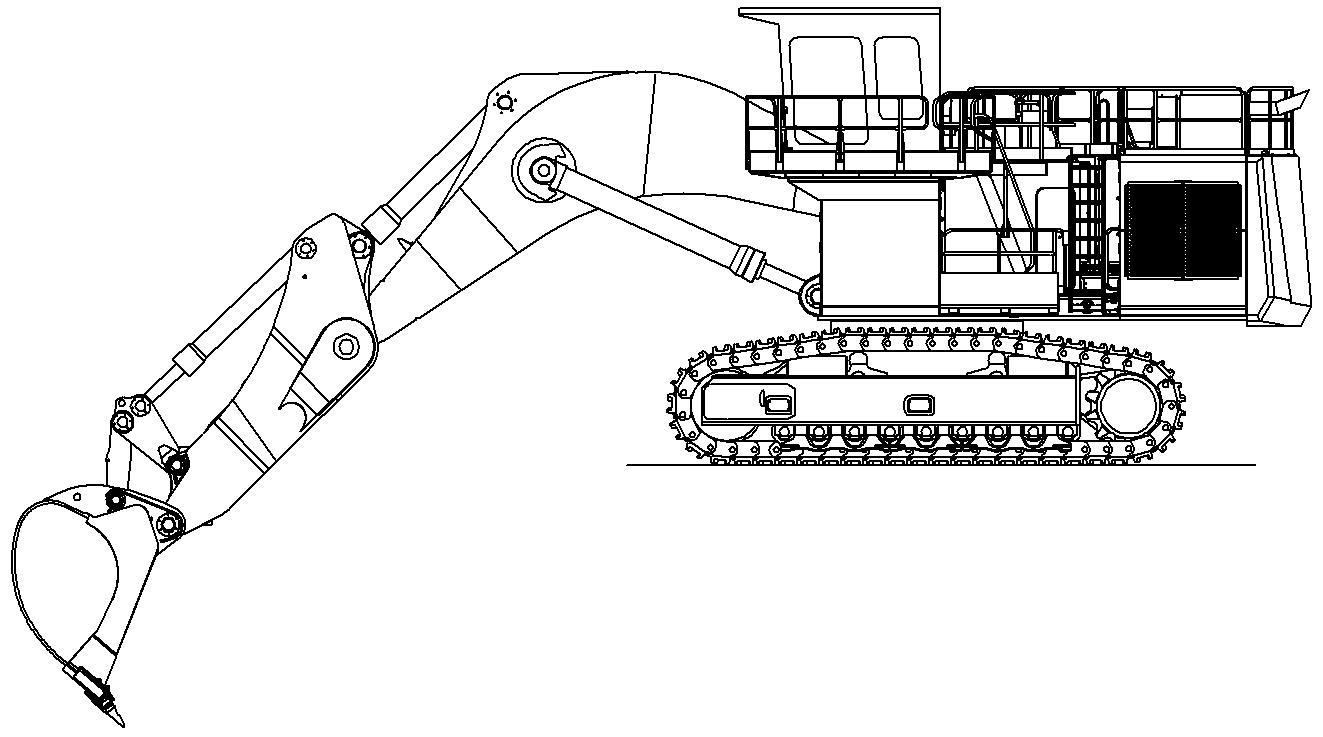
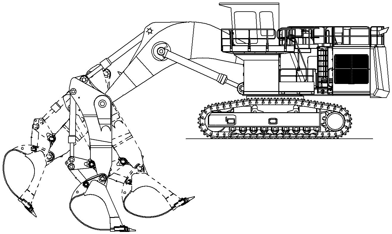
Fig. 3-78 Taking up grab material
To lift out the grab material, slowly and evenly slew in the shovel arm.
3-79 45° backward to the vertical
Assoonastheshovelarmisatanangle ofapprox.45°backwardtothe vertical, raisetheboomslowlyandevenlyinadditiontoslewingintheshovelarmandthe backhoe bucket. Stopping suddenly will result in impact loads and vibrations. When the backhoe bucket is full or the shovel arm can no longer be slewed in, raise the boom and backhoe bucket until the filled surface is parallel to the ground.
Note!
Foraefficientdigging,the of the shovel arm.
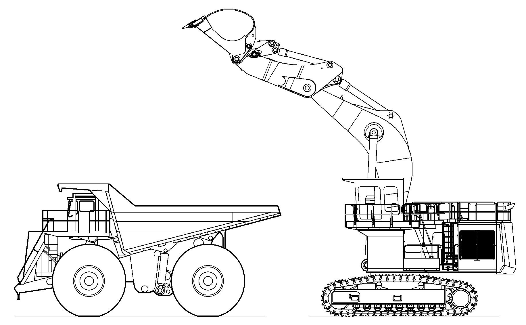
Loading the transport vehicle
Danger!
Risk of fatal injury due to falling grab material.
Do not load the transport vehicle so high that the grab material could drop out over the walls of the vehicle.
Ensure that nobody is standing in the danger.
Load an occupied truck only ifall safety requirements arefulfilled, notablyin order to protect the truck operator.
If possible, the machine should stand higher than the transport vehicle to avoid having to lift the grab material unnecessarily.
Stopthetransportvehicleinapositionthatallowsittobeloadedfrom therearor the side.
Slew the machine's equipment above the loading area of the transport vehicle. Distribute the grab material evenly over the loading area of the transport vehicle by slewing the backhoe bucket and shovel arm out, slewing the upper carriage and possibly also moving the boom.
Ifthebackhoebucketisnotsufficientlyemptiedorthereisstillgrabmaterialinthe backhoebucket, slew the backhoebucket inand out several times to loosen the grab material.
3.5.5Working with the Shovel bucket Digging
Tomaximisemachinepowerandbreakout,maintaingradeandfillthebucket,correct digging angles and technique should be used.
Fig. 3-81 Digging
Mostdiggingshouldbestartedwiththebucketalmostfullycrowdedback(50mm off stops or end of cylinders).
When cleaning up or digging at floor level, angle the teeth aggressively to break out any toe that may be encountered.
Keepingtheheelofthe bucketoffthegroundthereforecreatingavoid underthe rear of the bucket.
Operate with the teeth and bucket lip doing all the work.
Note!
Avoid digging at right angles to the tracks.
Caution!
Each timethestick is crowdedback to commence a cut, extreme cautionmust be taken not to hit the tracks.
The clam must always be closed when Avoid working on the cylinder limits and bucket stops duringthe digging cycle. Continual use of these practises will lead to premature failure of seals and Orings andcancausestress fractures totheclam, stick and bucket anddamage to the boom and superstructure.
Crowd the bucket in (down) while closing the clam. This practise makes use of gravity to help minimise shock loading on the bucket cylinders.
Neverdig,orattempttobringdownanymaterialoverhang,withthebucketwhile the clam is open or partly open.
Do not attempt to dig or clean the floor or face with the clam open. These practises can cause considerable damage to the clam cylinders.
Unload the bucket
Fig. 3-82 Unloading of the bucket
Whendumpingtheload,tipthebucketforwardslightlyastheclamopens.Thishelps direct the material to fall centrally into the tray and avoids spillage.
Thepositionofthebucketbackboardwhentheclamopens,directlyaffects theposition of the load in the tray.
Bucket in ideal position resulting in material falling straight down. Loading centre of the haul truck.
3.6Transport
3.6.1Travelling procedures for mining machine
Thelifeexpectancyofundercarriagecomponentsisbasedonstandardworkingconditions with a maximum travel ratio of 5% per service meter unit. Working and / or travelling on uneven ground and / or abrasive material will influence the lifetime of the components and attract additional cost for the undercarriage components.
Downhilloruphilltravelonaslopehasalsoaneffectonthelifeexpectancyofundercarriagecomponentsandontheirwearrate.Indeed,eveniftheslopeangleisbelow the maximum permitted travelling angle, the increase of the slope angle causes the increase of the force and of the contact pressures applied on all track components (trackpadassembly,sprocket,...).Onanindicativebasis,thetravelforceappliedon thetrackcomponentsismultipliedbytwofromaslopeangleof5°(8,7%)andismultiplied by 2,5 from a slope angle of 10° (17,6%).
In general travel action has to be kept to the lowest level that is possible. Minimize travelling with turning through a narrow turning circle and long distance travel.
To minimize the travel ratio, professional mine planning with longfront winning sectionsispreferred.Ifdiggingoperationsatvariousspotsarenecessary,apropershort termandlongtermplanofwinningoperationshastobeemployedtoguaranteelong term use of the excavator at one place before moving to another location.
However, if frequent machine movement is necessary, the following set of procedures defined by Liebherr to minimize possible machine damage, downtime and wear have to be taken into consideration.
General
In order tomove the machine forwards:with theexcavator in standardforward position, depress travel pedals all the way forward with the toes. Direction of travel is in the direction of idlers.
Inordertomovethemachinebackwards:withtheexcavatorinstandardforwardposition, depress travel pedals all the way down with the heels. Direction of travel is in direction of the drive sprockets.
Moving the machine during loading operations
Moving the machine during loading operations means adjustment of excavator digging and / or truck loading position of some meters.
Important procedures: cket and close up the attachment to a position as close as possible to the excavator undercarriage. onthegroundandliftingthemachine,then counter turning theundercarriage, isnot allowed, becauseit could causepremature structural damage to the machine. terialaroundthetrackswherethemachinewillnotturn, you mustmove the machine several meters forwards and/ or backwards and attempt to turn again. ator can use theswing function to assist inturningthetracks,i.e.ifturningtotheright,swingupperdecktotheleftandvice versa.
Walking themachine over distance
Fig. 3-83 Hazard area r
Walking the machine distances means any movement of the machine of more than 100 m or for a time period longer than 3 minutes, whatever comes first.
Inadditiontoabovementionedguidelines,whenmovingthemachineduringloading operations, the following procedures apply: cleanall very dirty parts oftheundercarriage and remove the unwanted materials. with a heat gun, to monitor the temperature of the drive components, including the track and carrier rollers.
Danger!
Duringthemovementofthemachine,thepersonwhichischeckingthetemperature of the different rollers must always be out of the hazard area r of the machine and
For the checking of the temperature, the excavator should stop moving. And only when the excavator is stopped, the person could go in the hazard area r to check the temperature of the different rollers. The machine couldonly start moving againwhen the driver has seen the operator out of the hazard area r perature, interrupt travel and only commence again after parts have sufficiently cooled. travellingortospeedupcoolingprocedureitisadvisable to have a water truck standby, to hose the heating components during travelling or cooling break. venewithminesafetyregulations,swingwhilsttravellingtoequallyloadtrackrollers. However, always ensure that clear forward vision is maintained.
Travelling the machine down grades or upgrades
Inadditiontoabovementionedguidelines,whenmovingthemachineduringloading operations or when walking the machine distances, the following procedures apply: themachinedownwiththetrackmotorfirst,i.e.themachineismovedbackwards. thefinaldrivesmustbeattherearoftheexcavator. indicatedinthe"Technical data"section of this manual(machine mustbe able to walk up unaided). When moving down the ramp never allow the machine to fall downontheattachment. Whenwalkinguptherampneveruseattachmentto assist the movement by pushing with the hydraulic power of the bucket, stick or boom.
Travelling the machine first time
The slide bearing (friction bearing) of the track rollers needs some time for runningin.Ifthebearingbecomeshotatanearlystageof machinelife,thismaycauselubrication problems during further life. Therefore when travelling the machine the first time aside from all above mentioned guidelines it is strongly recommended to move carefully and at reduced speed.
Note!
Warrantymaybecomevoidiffailuretorecognizeandcomplywiththerecommended travel operating procedures, as outlined in this document, is noted.
3.6.2Excavator lifting and lashing operations
Danger!
For safety reasons, always consider the precautions given in this section.
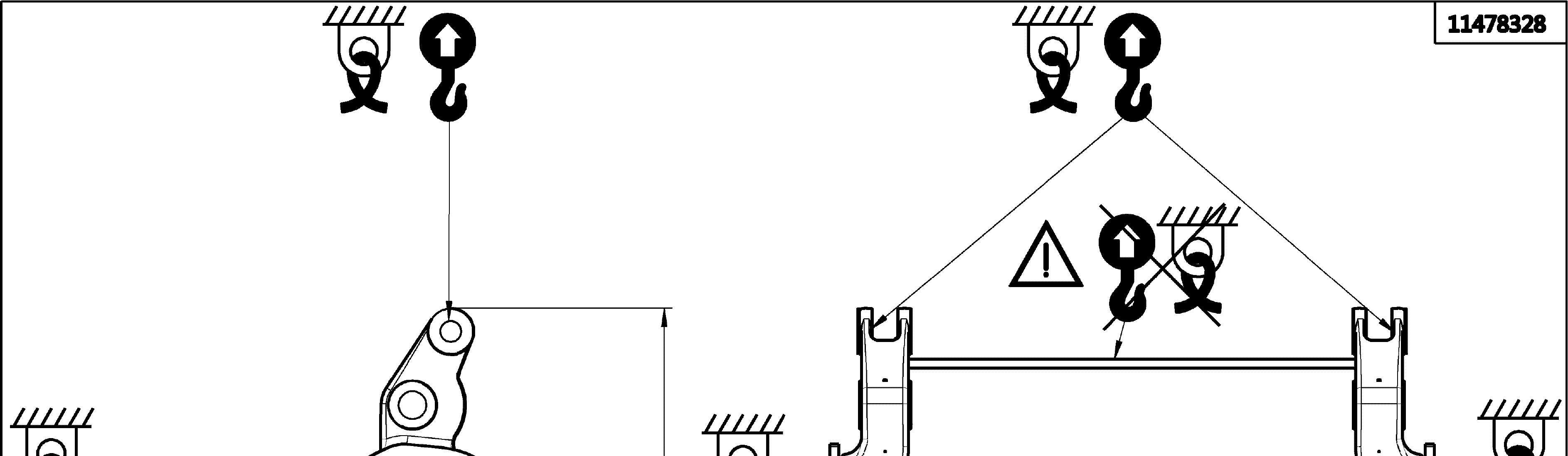
Lifting precautions
Lift element: spondingtransport drawing, s of other kind (cables, chains, slings) if necessary, nces in accordance with the regulations, gs shown on the assembly drawing, ement has been already dismounted, e corresponding transport drawing, always respecting the angles given on the sticker for lifting and lashing operations (refer to the description below).
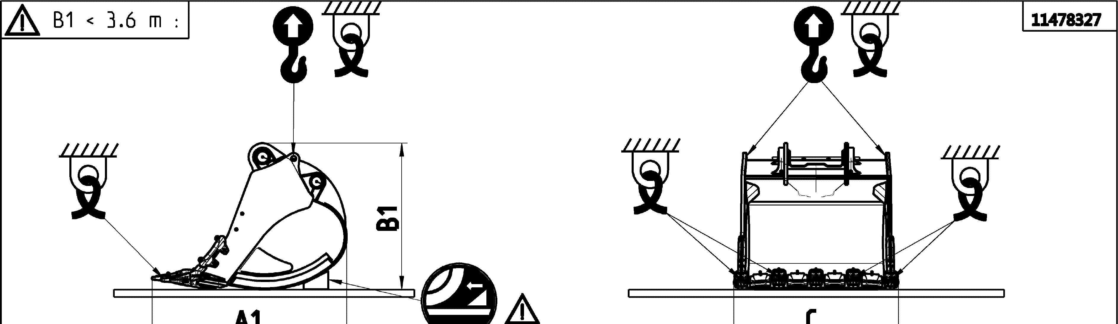
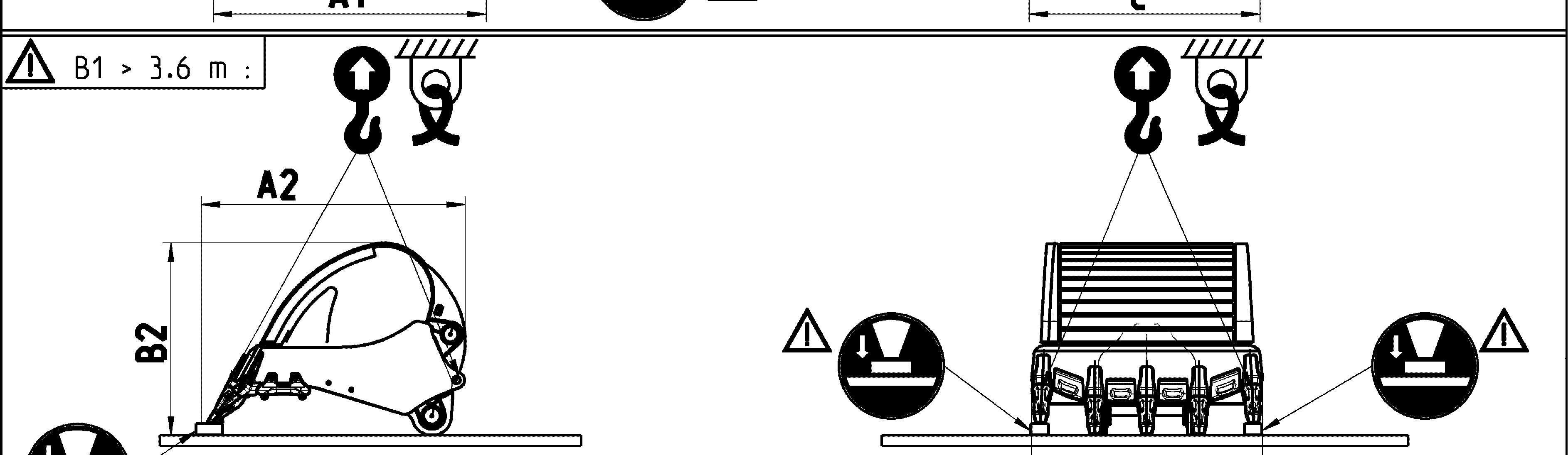
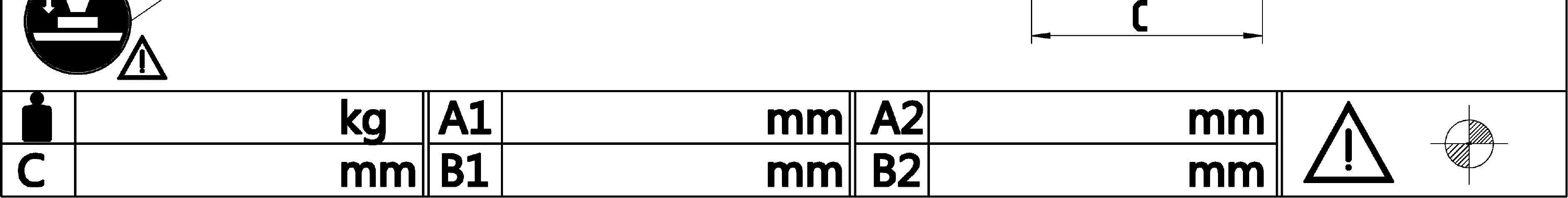
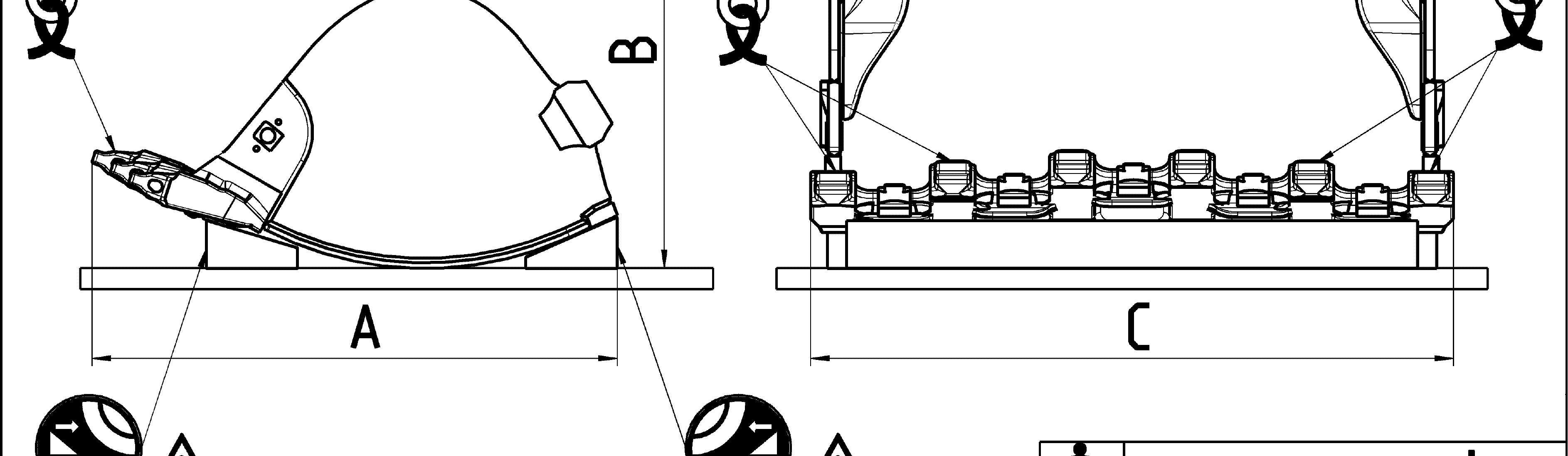
Additional lifting precautions for backhoe buckets
When you lift the backhoe bucket, also obey theprecautions that follow: he center of gravity of the bucket. tions. The height B1 gives the correct transport position as shown in the transport drawing.
Additional lifting precautions for shovel buckets
When you lift the shovel bucket, also obey the precautions that follow:
Lashing precautions
Lash element: in order to ensure safe lashing, he center of gravity of the bucket. g configuration indicated on the correspondingtransport drawing, e corresponding transport drawing, always respecting the angles given on the sticker for lifting and lashing operations (refer to the description below), supporting surface so as to avoid element to slip (e.g. using wooden parts, nonslip mats...), friction is guaranteed by manufacturer certificates, between each contact surface (e.g. between the load and the support, between the support and the flatbed trailer), carried are free of dirt, ice, snow, oil and grease.
Additional lashing precautions for backhoe buckets e center of gravity of the bucket. transport position as shown in the transport drawing. 6 m, turn over the bucket safely.
When you lash the backhoe bucket, also obey the precautions that follow: the stickers placed on the bucket.
Additional lashing precautions for shovel buckets e center of gravity of the bucket.
When you lash the shovel bucket, also obey the precautions that follow: the stickers placed on the bucket.
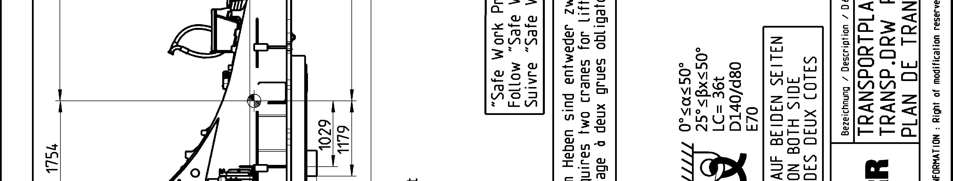
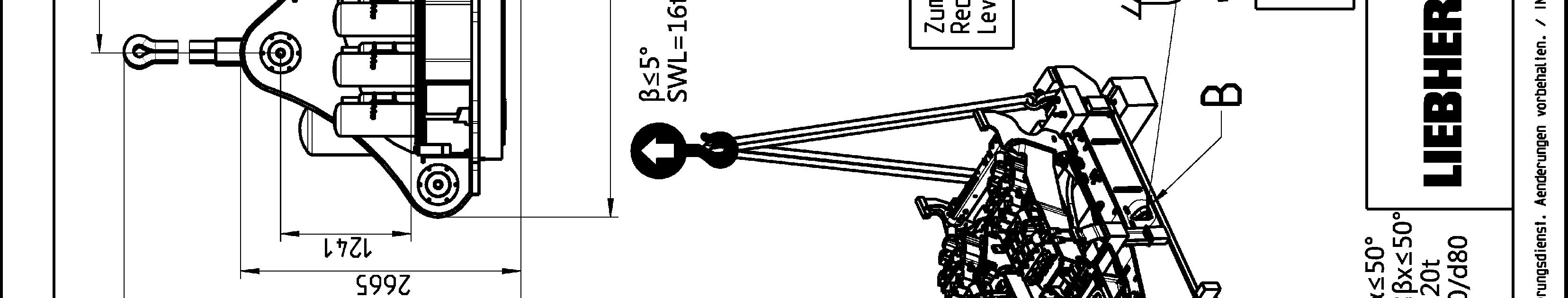
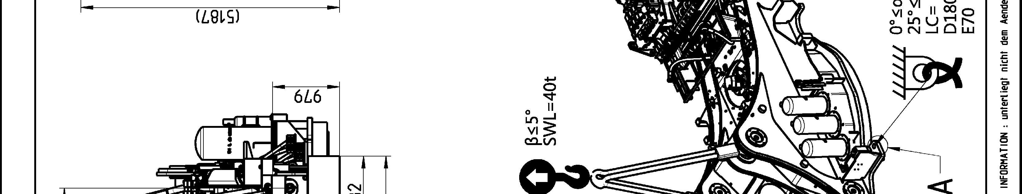
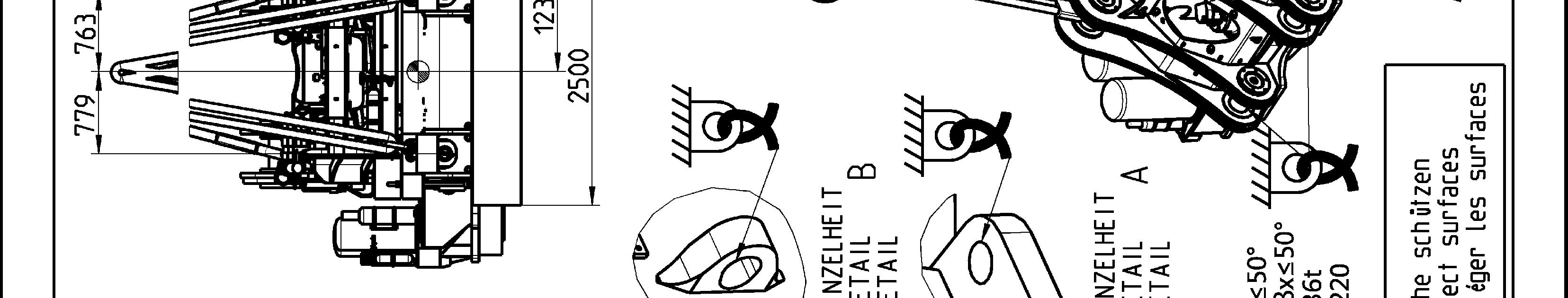
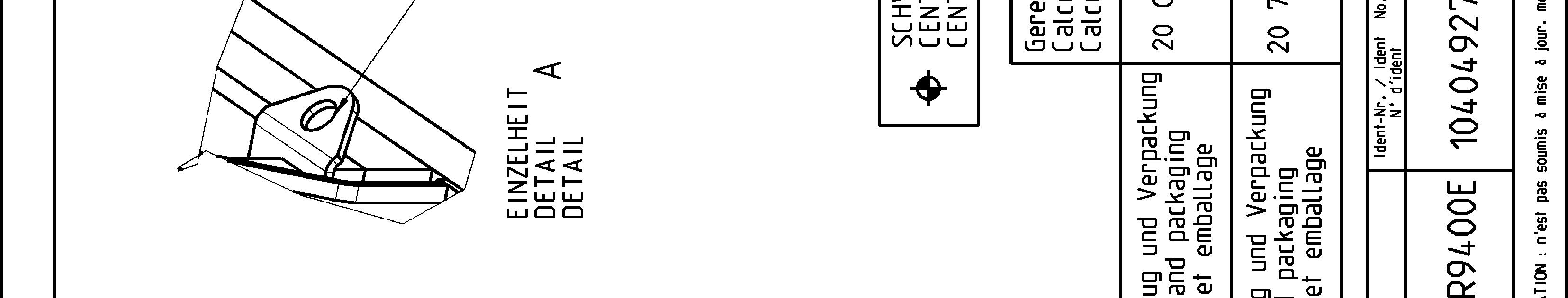
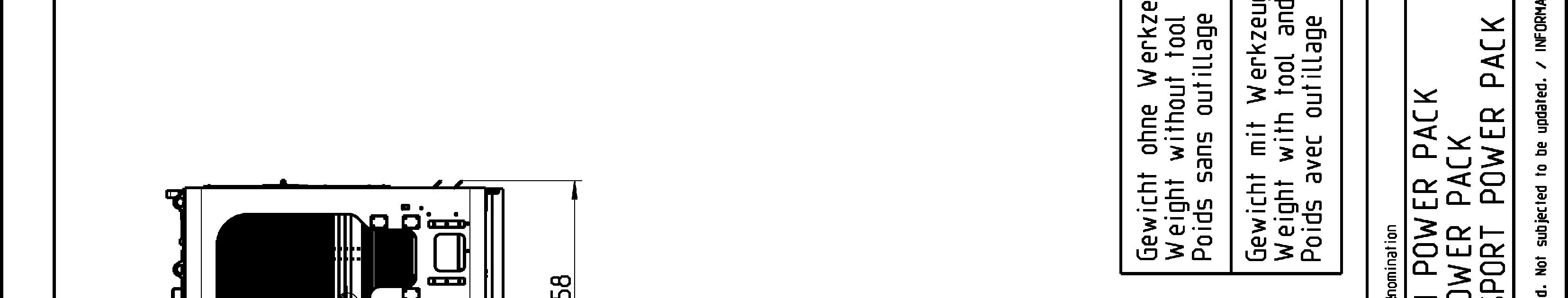
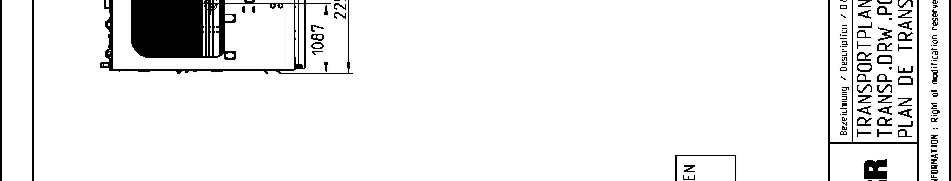
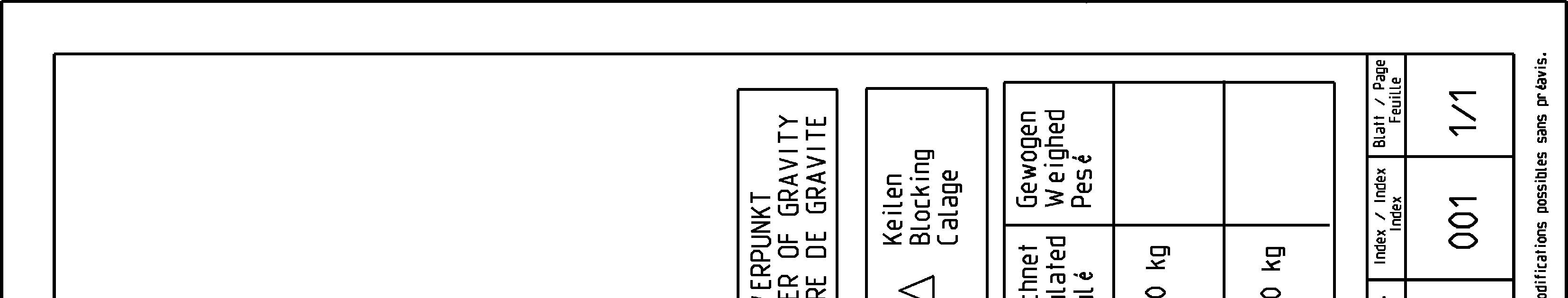
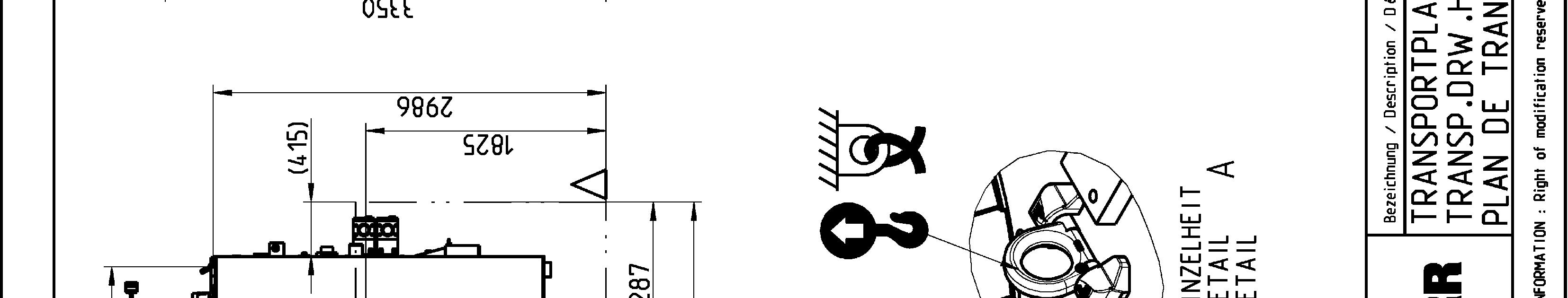
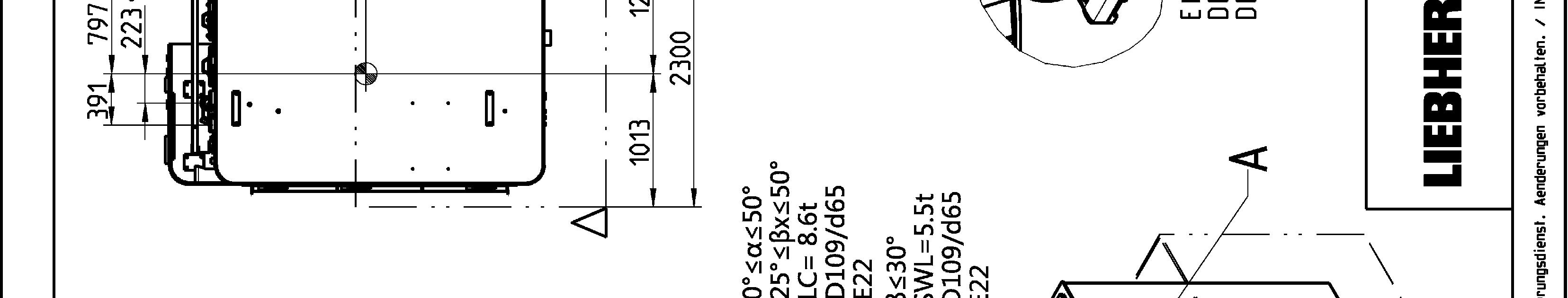
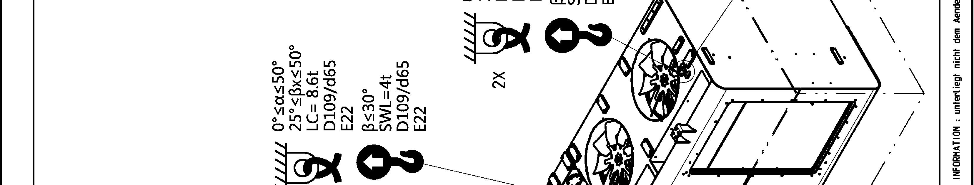
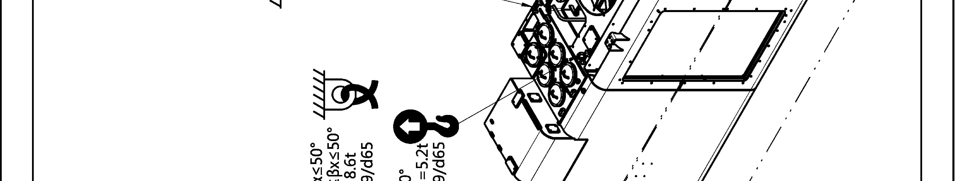
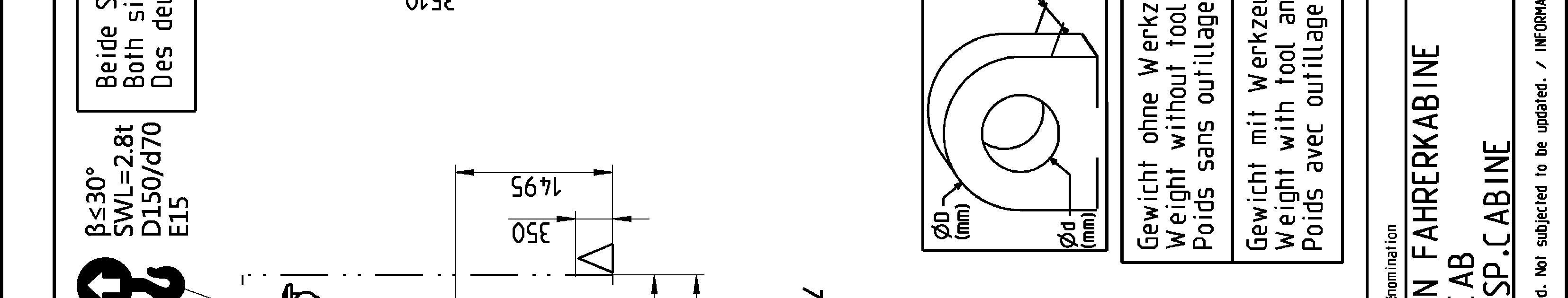
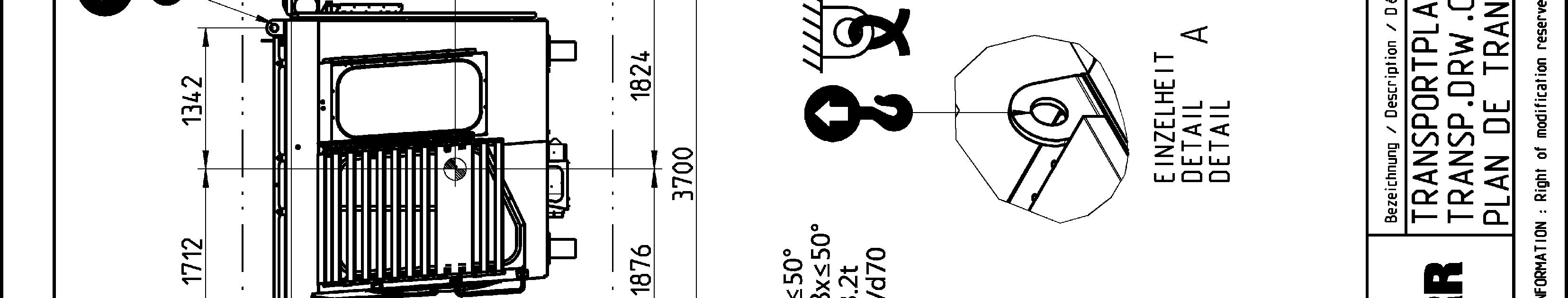
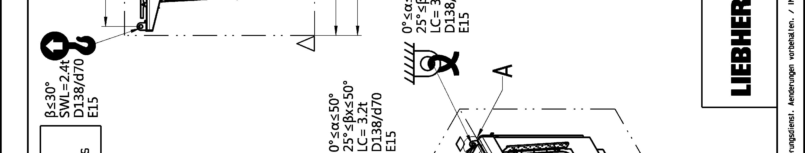
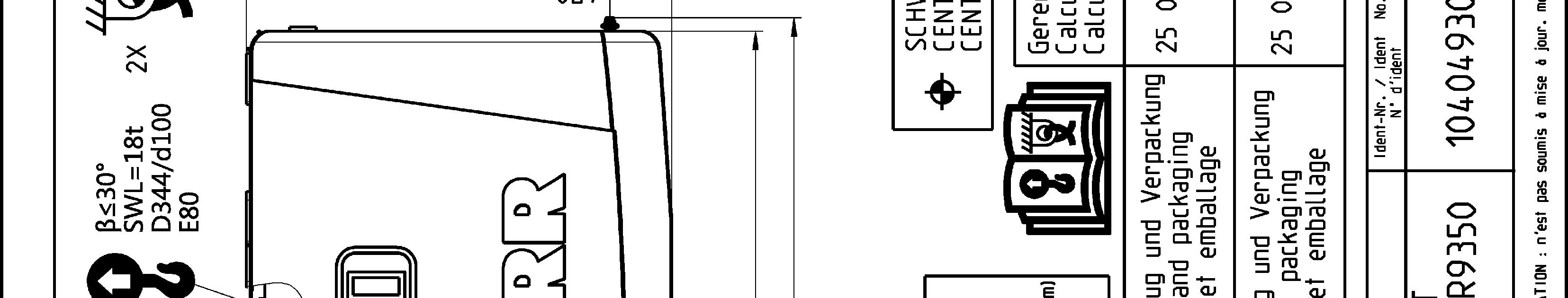
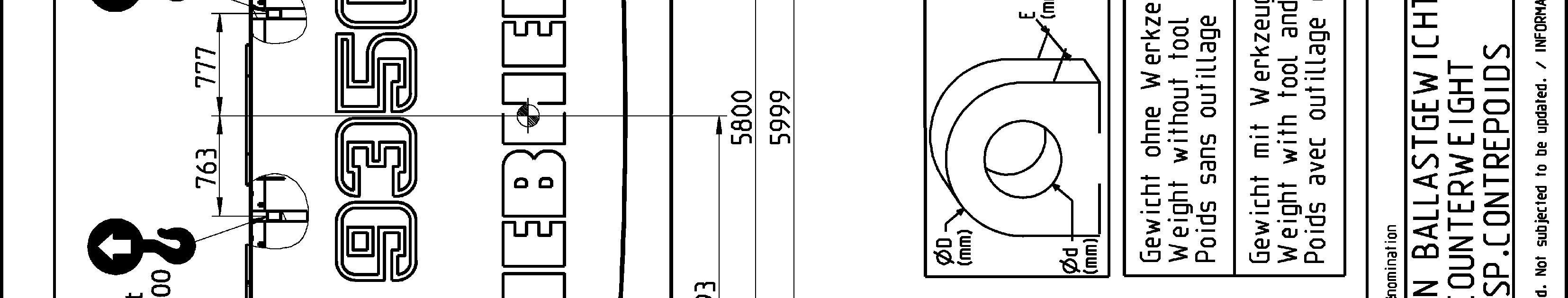
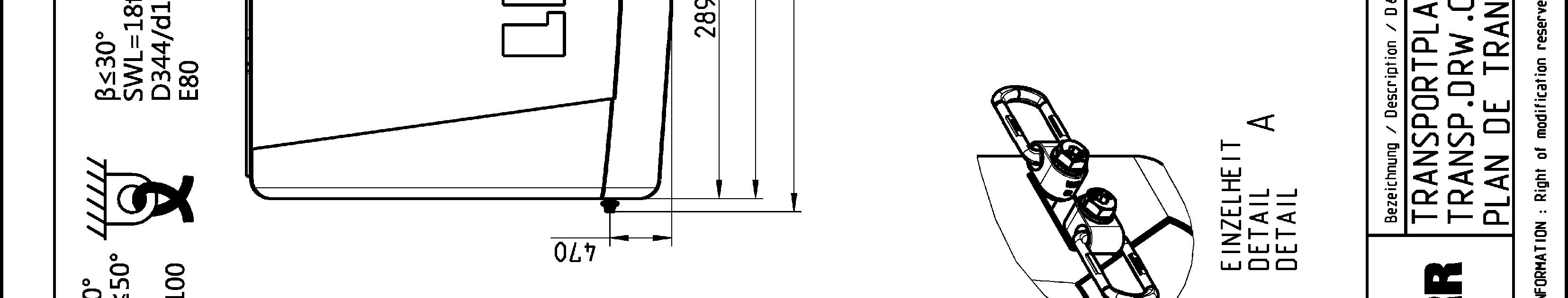
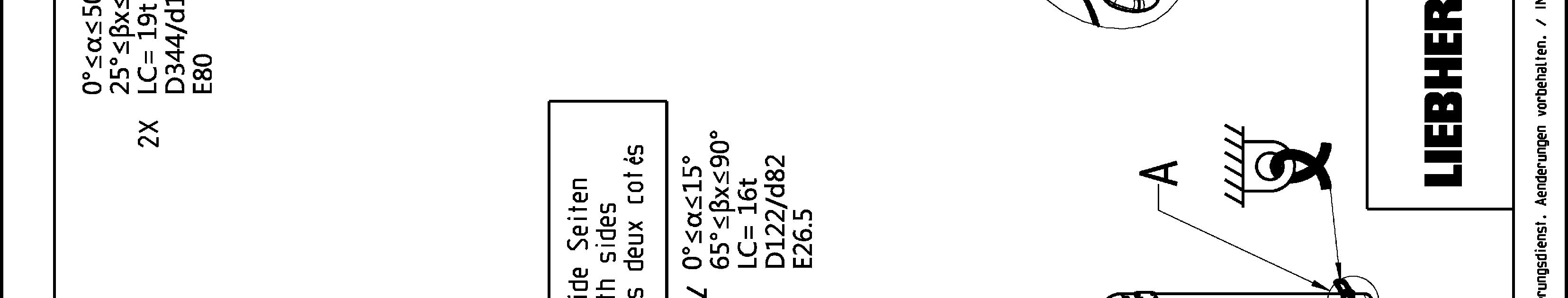
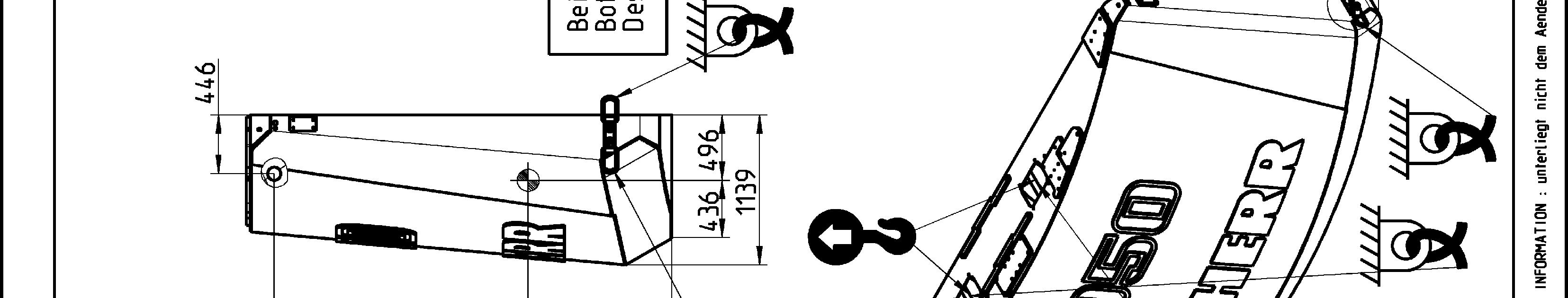
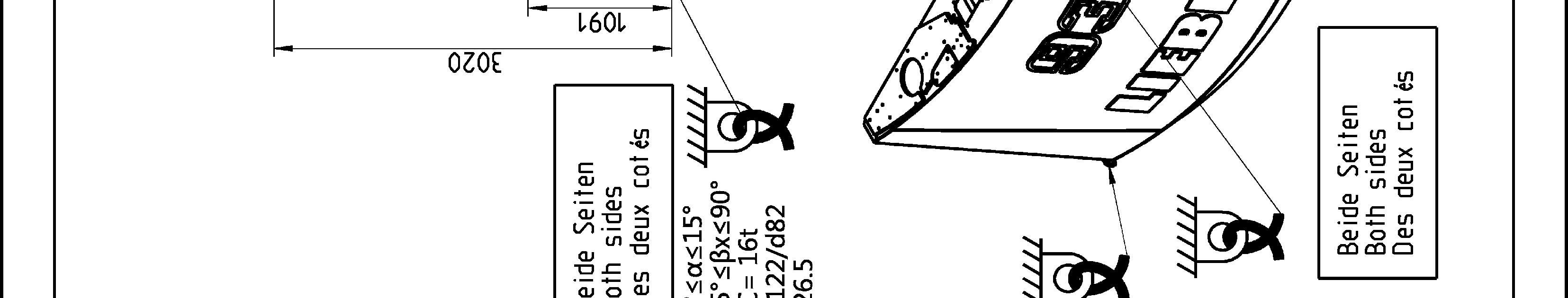
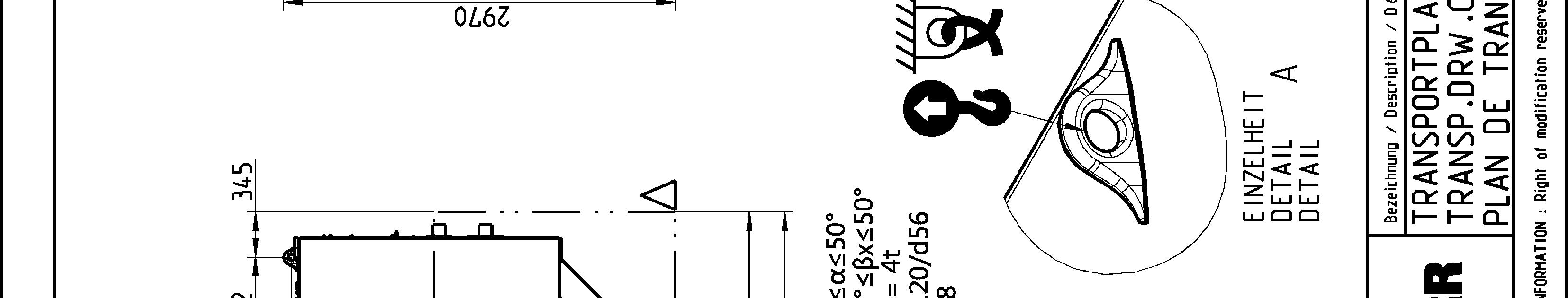
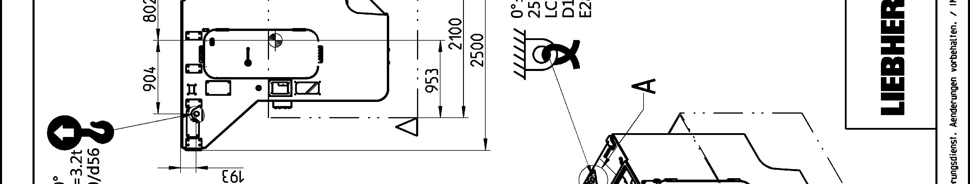
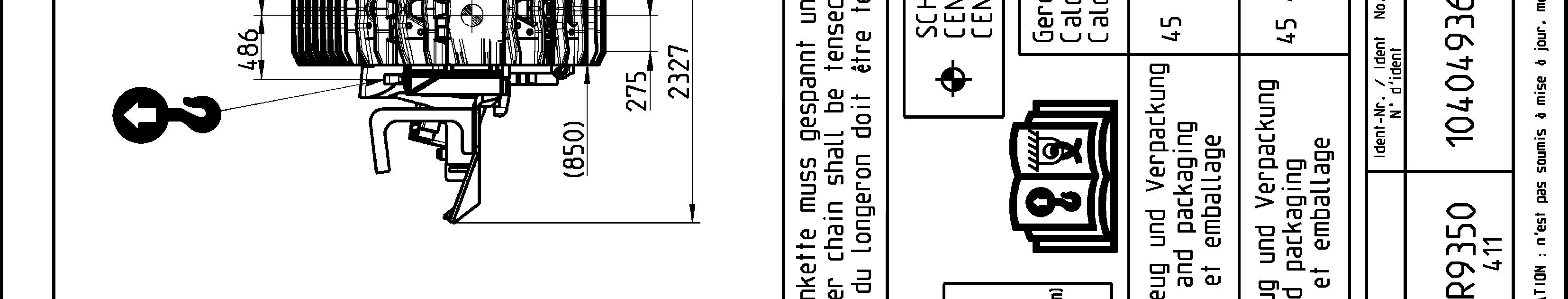
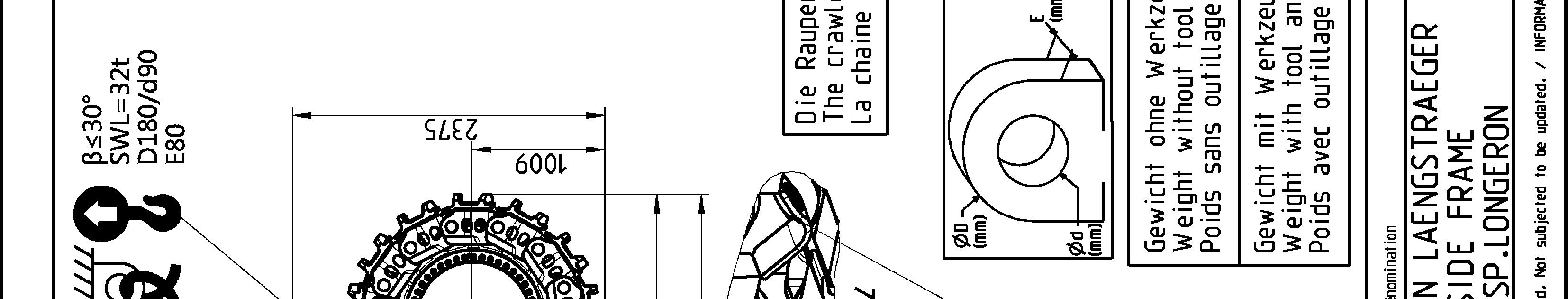
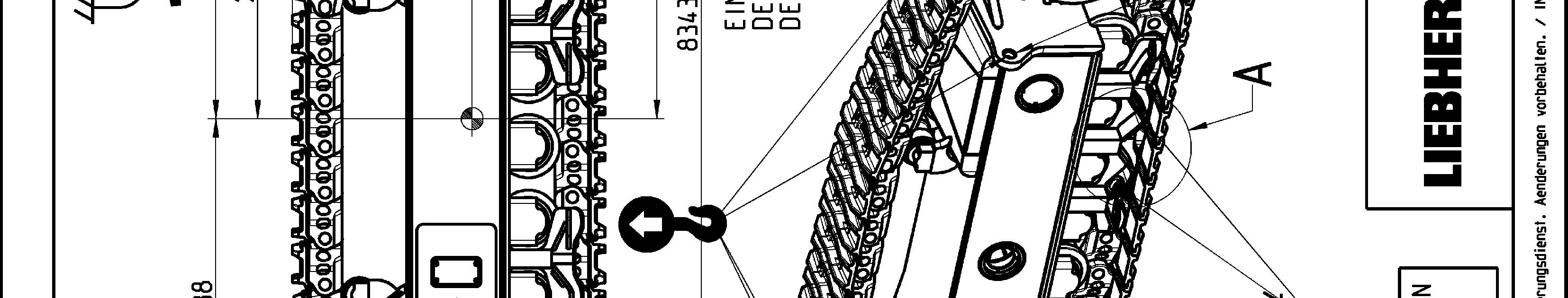
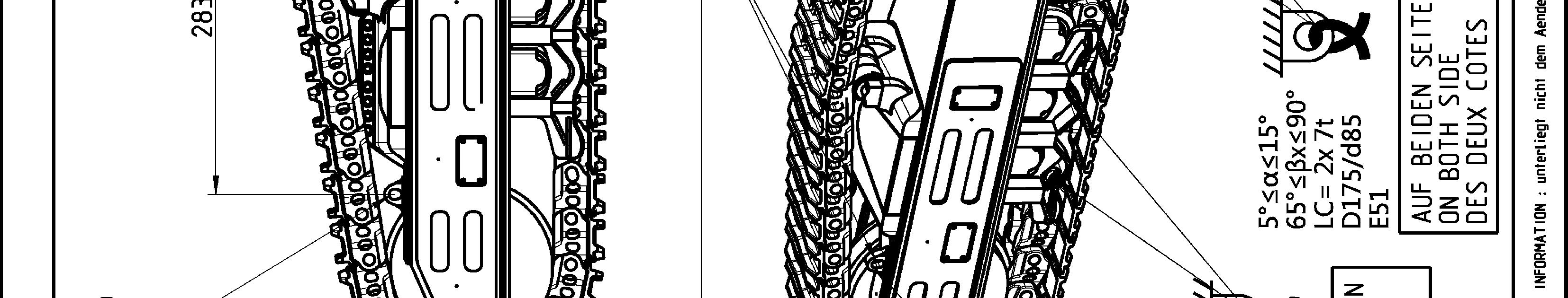
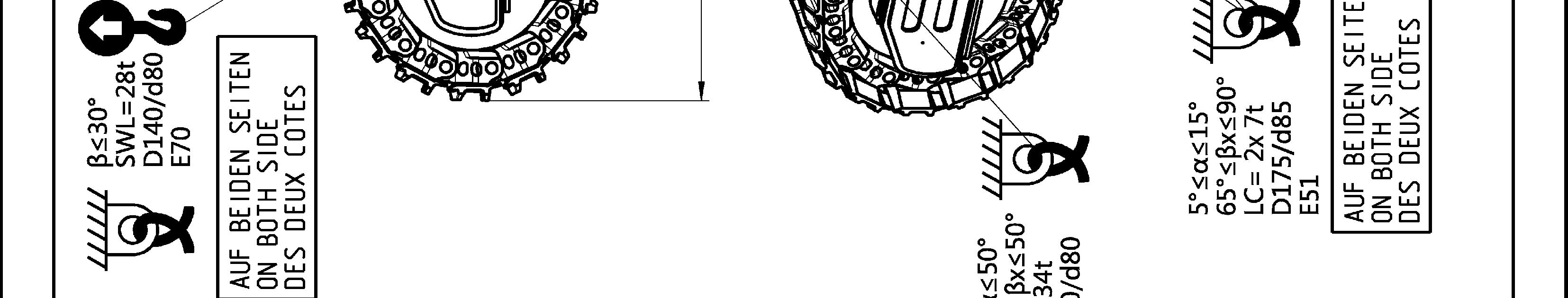
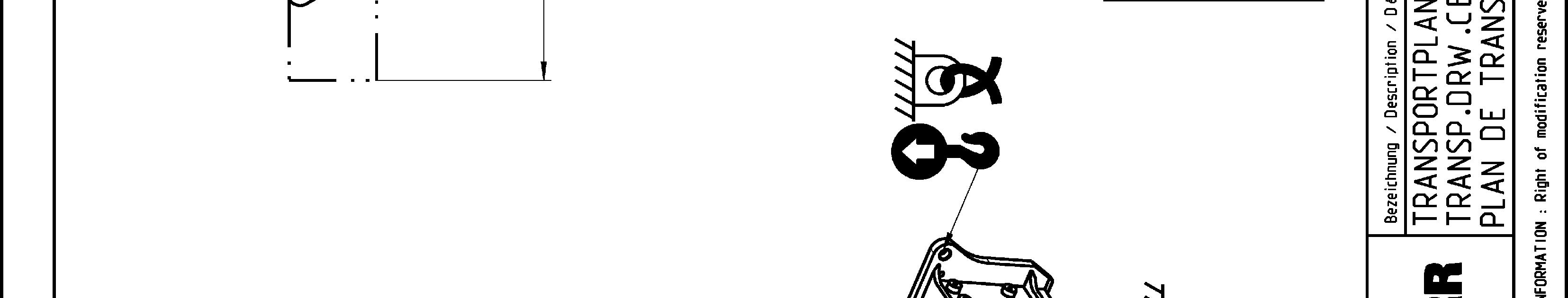
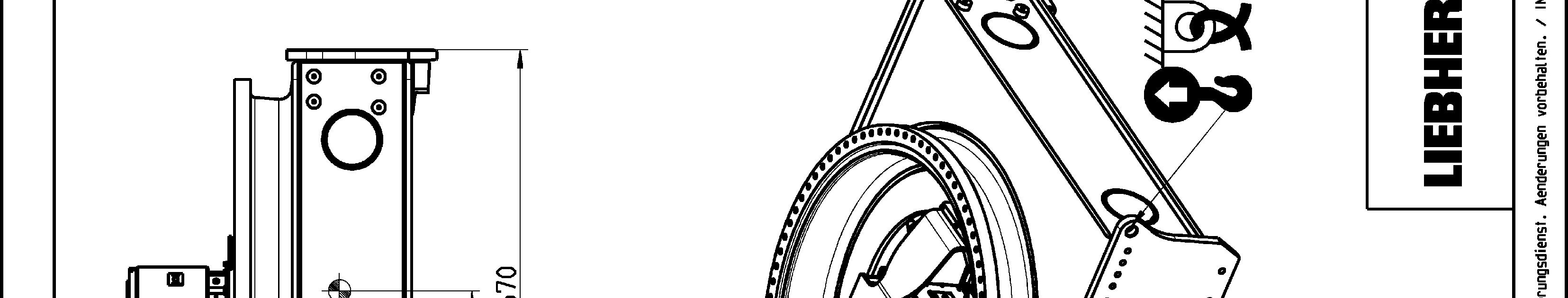
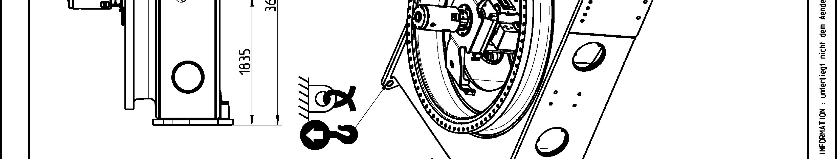
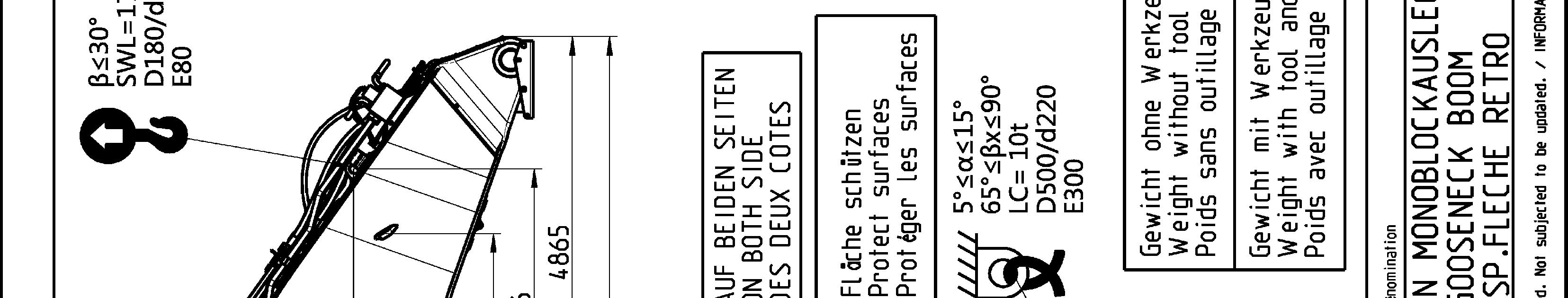
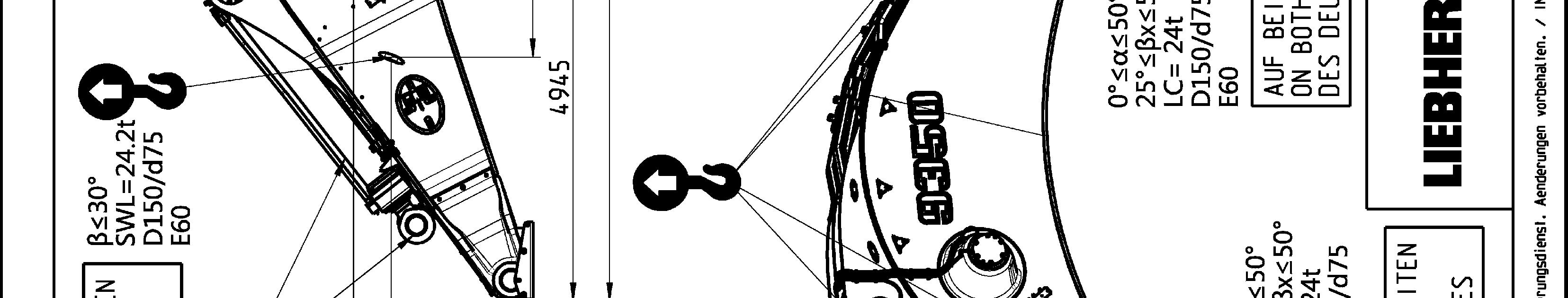
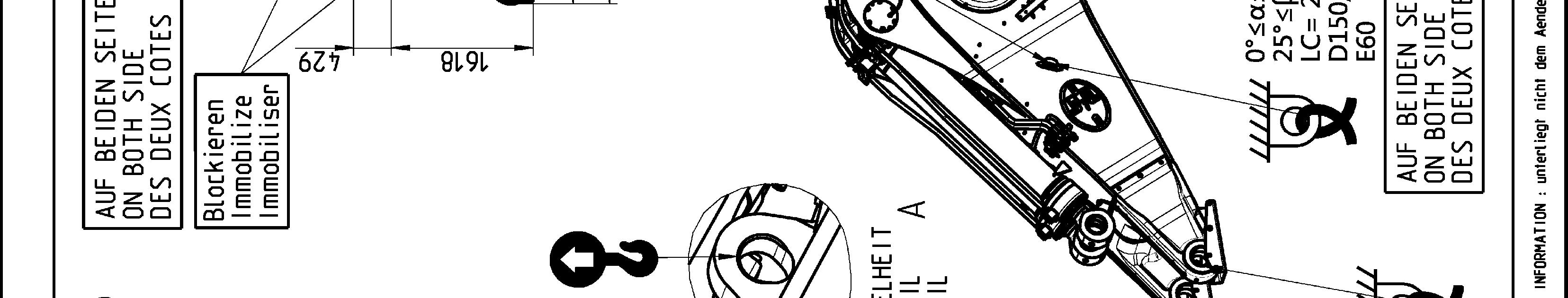
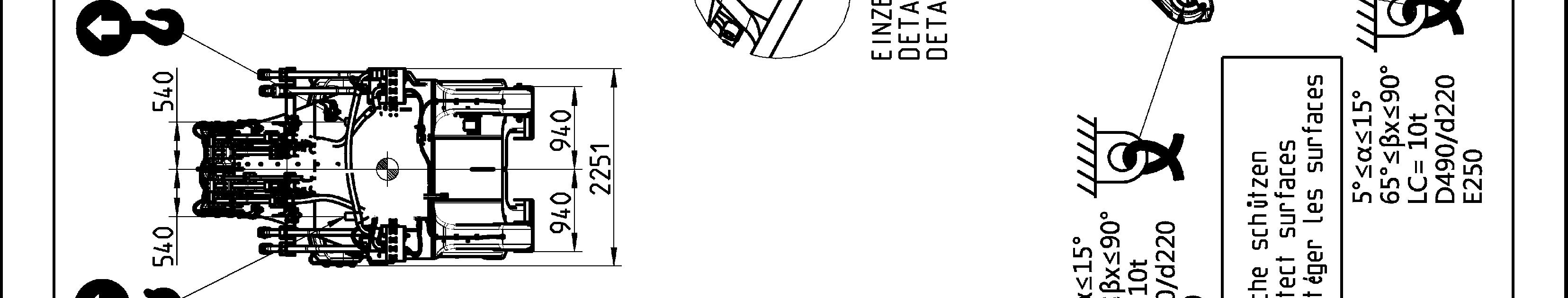
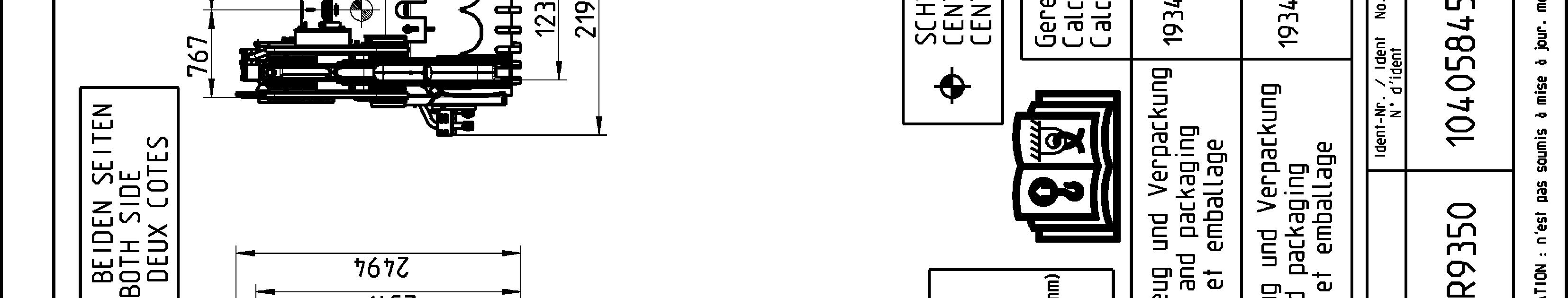
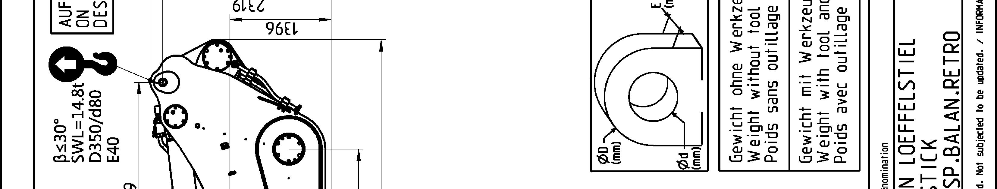
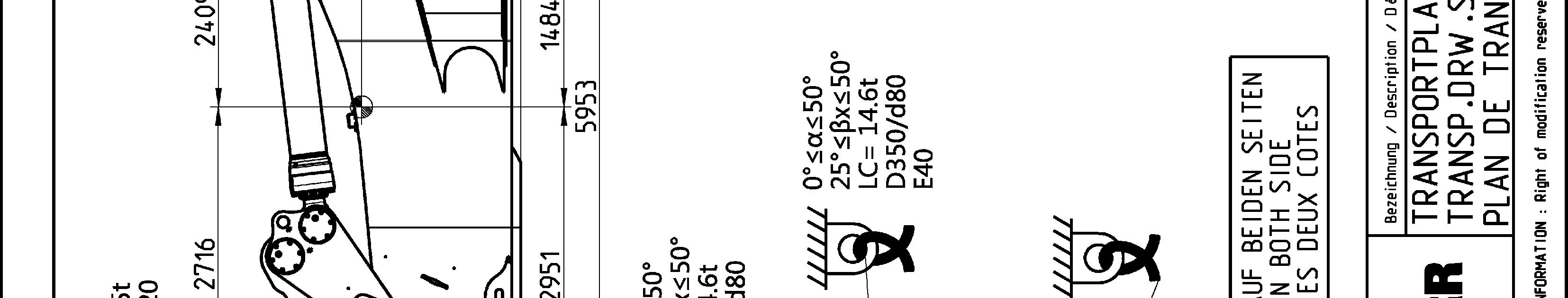
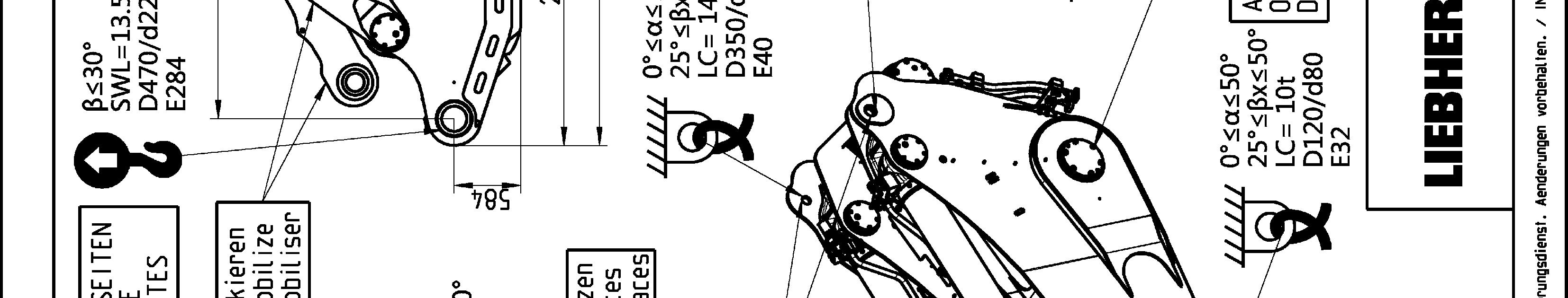
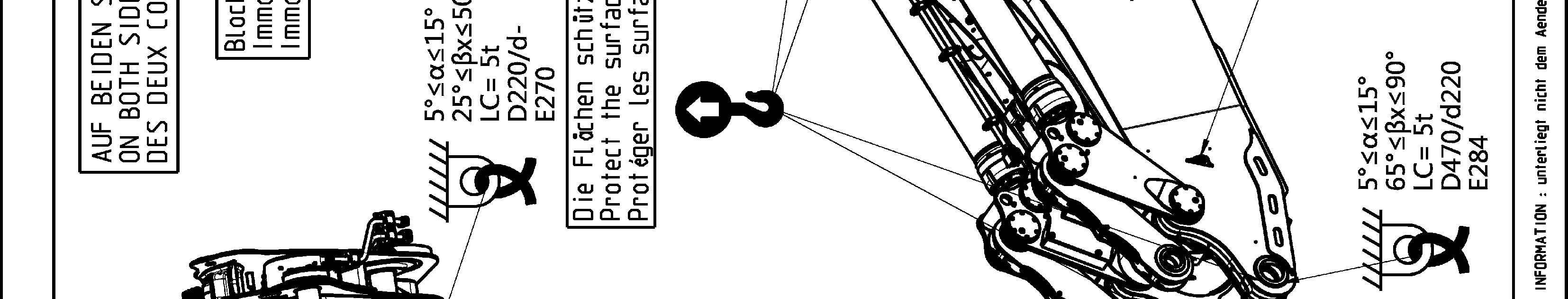
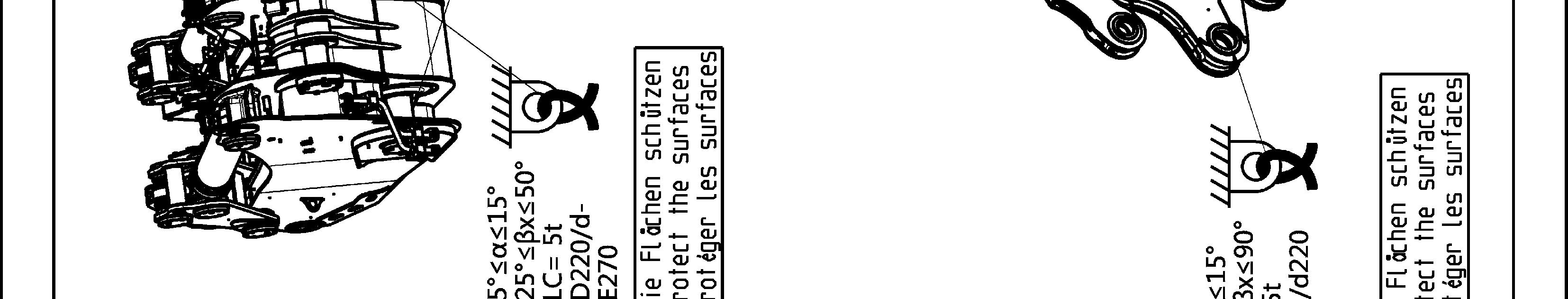
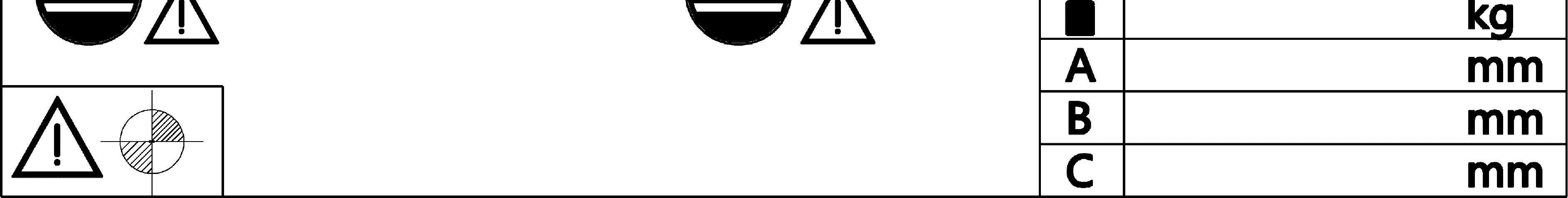
Sticker for lifting and lashing operations
Thefollowingstickerisplacednexttoeachtransportdrawingontherelatedpartand package. It shows rules and precautions which you must obey for transport operations.
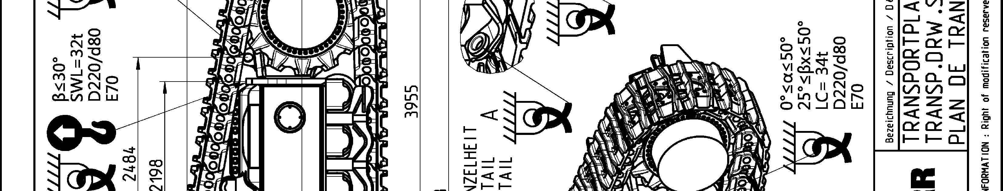
The Lashing Capacity LC is the maximum force that the lashing ring can hold in accordance with the angles given on the transport drawing.
TheSafeWorkingLoadSWL isthemaximumloadthattheliftingringcanholdinaccordance with the angles given on the transport drawing.
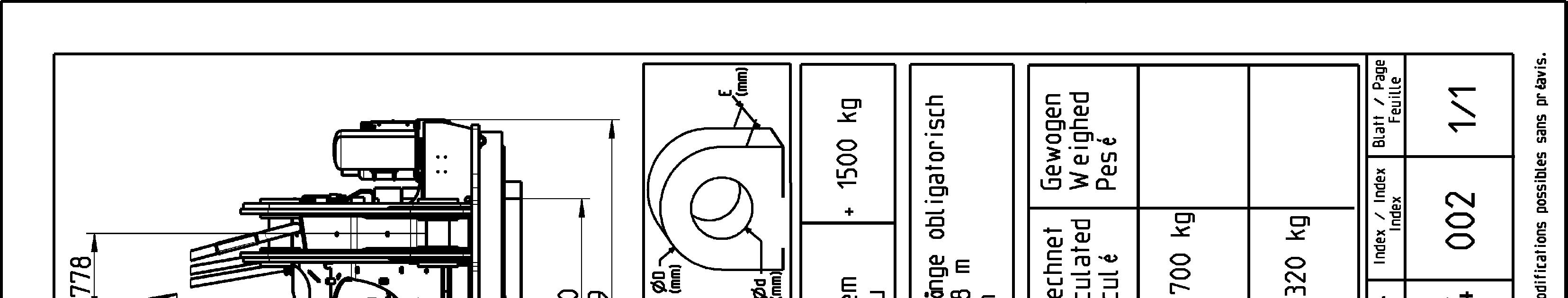
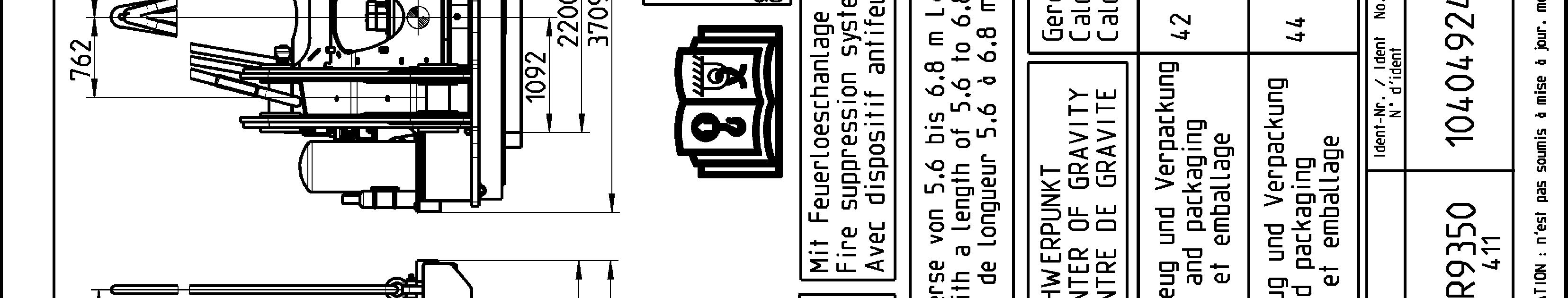
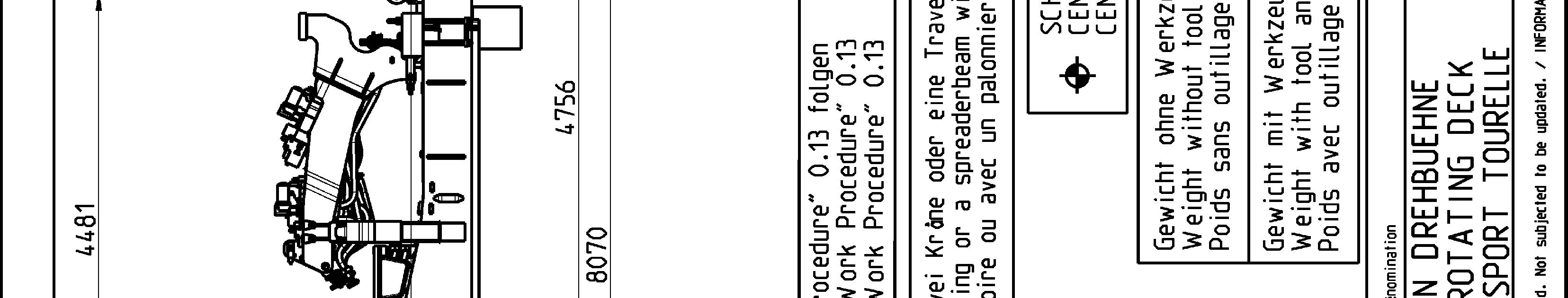
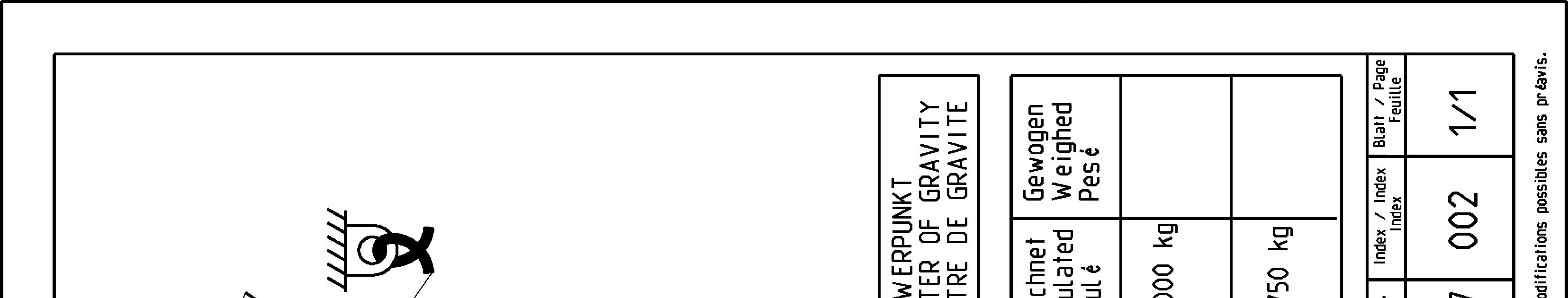
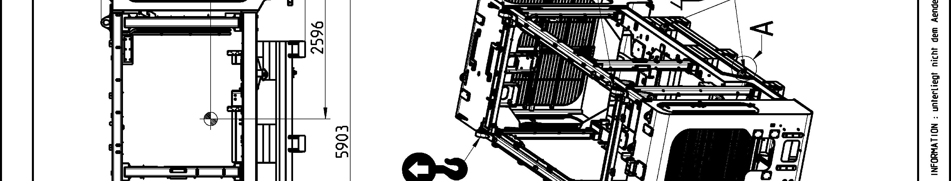
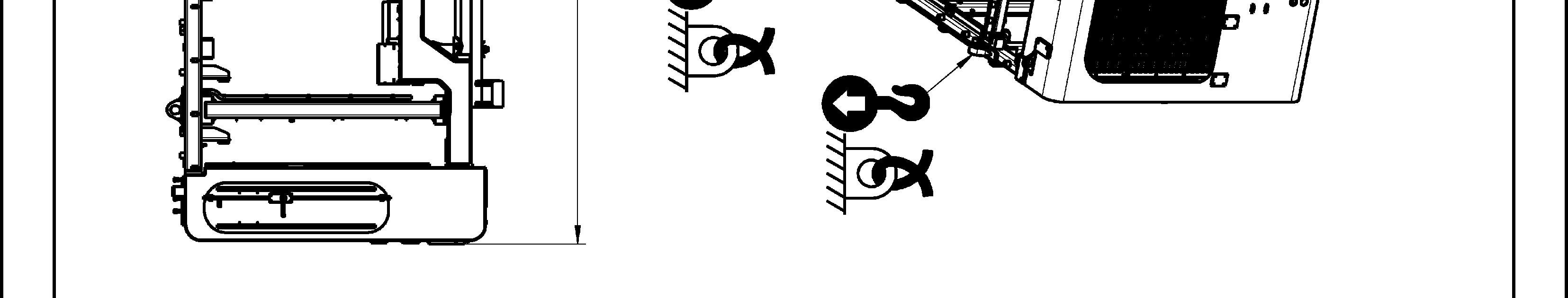
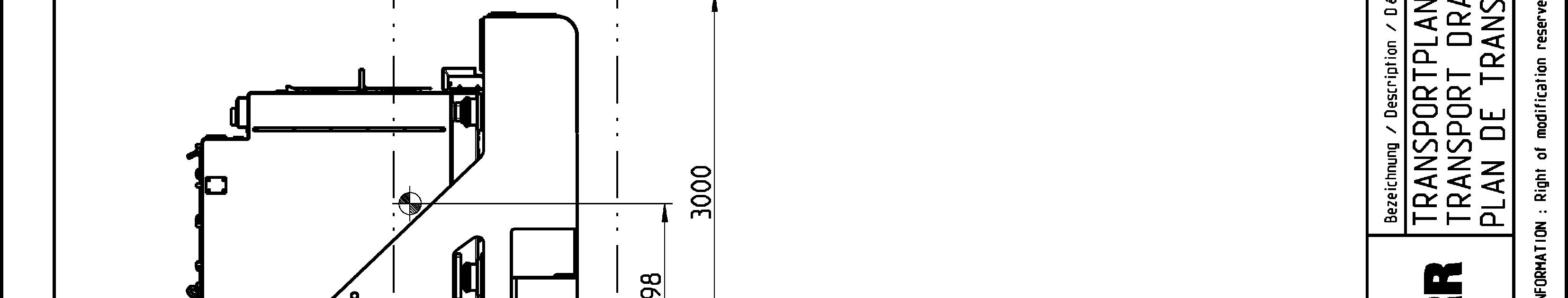
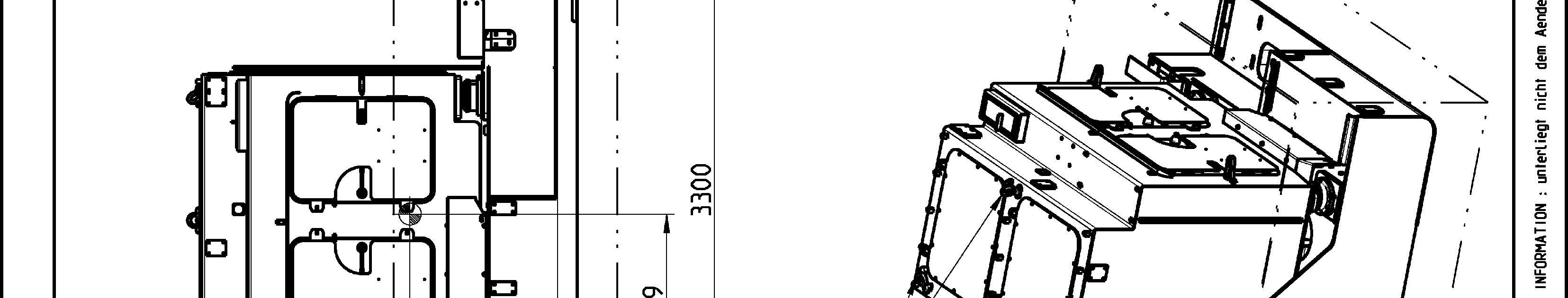
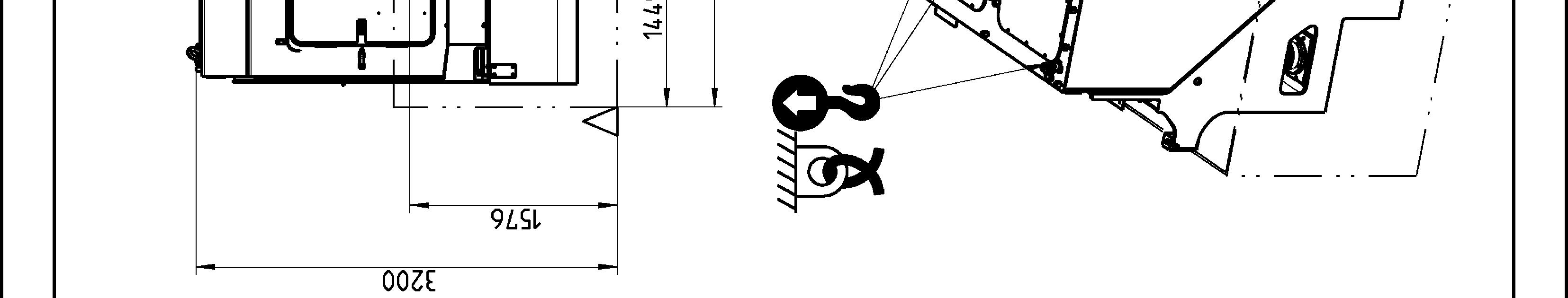
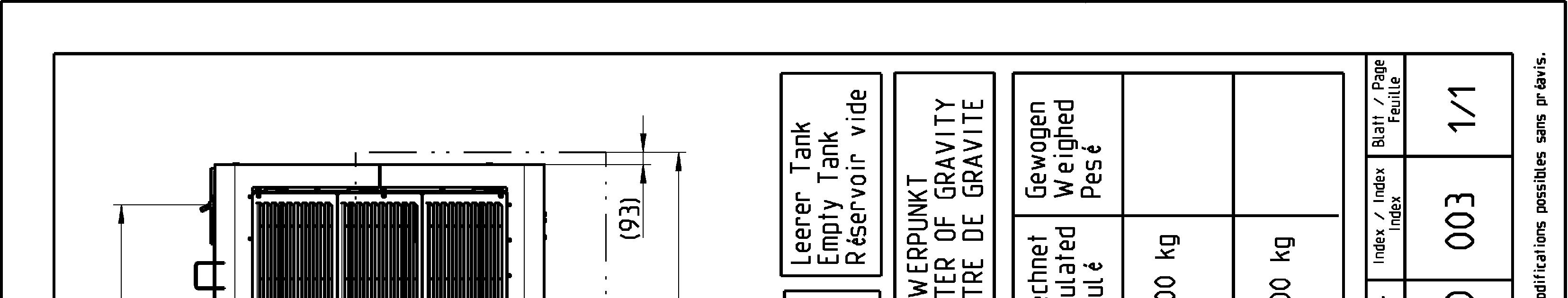
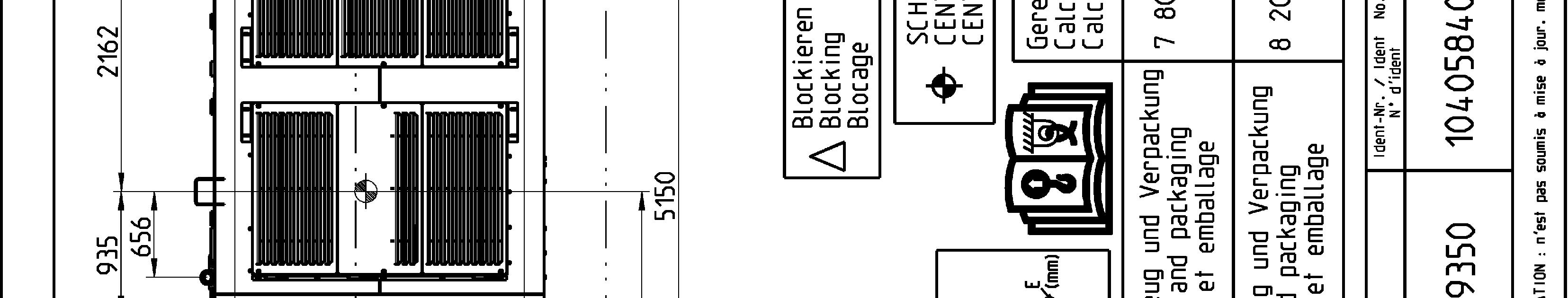
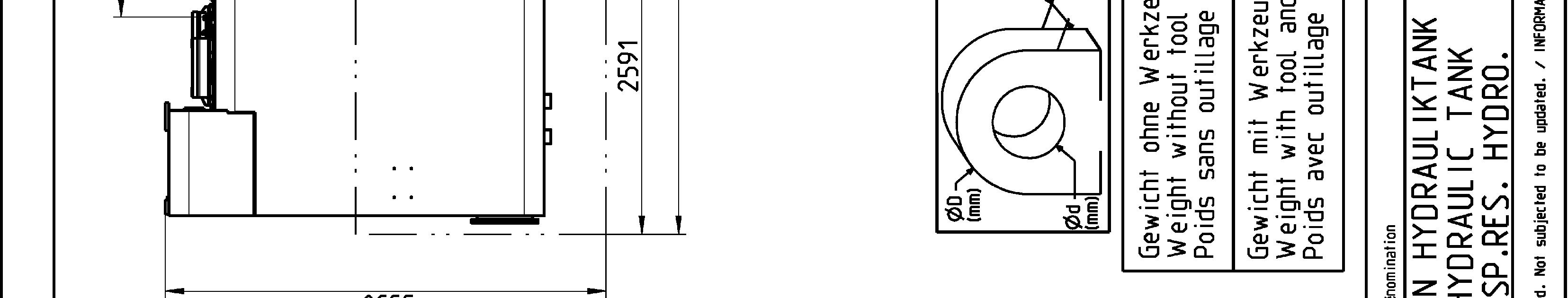
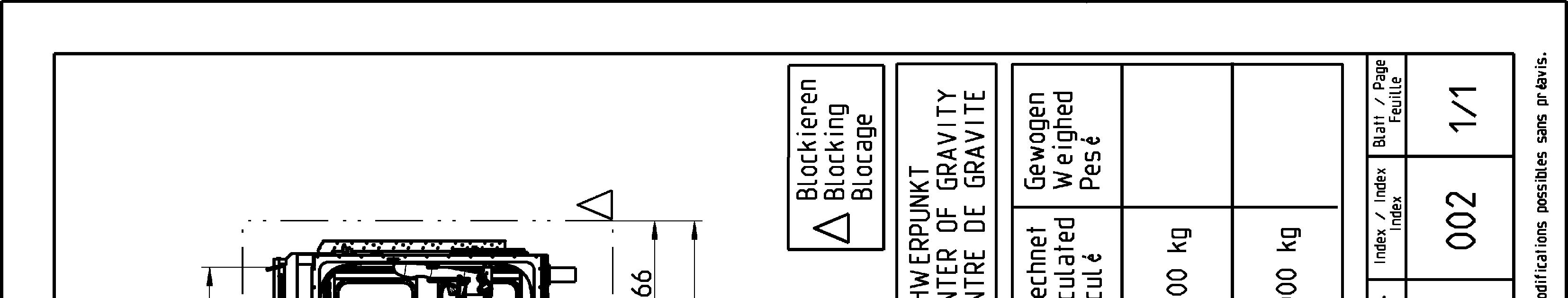
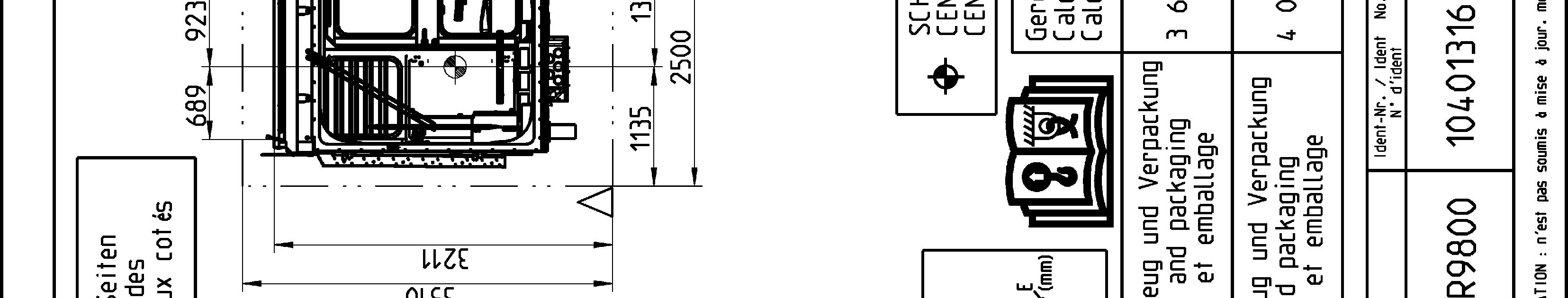
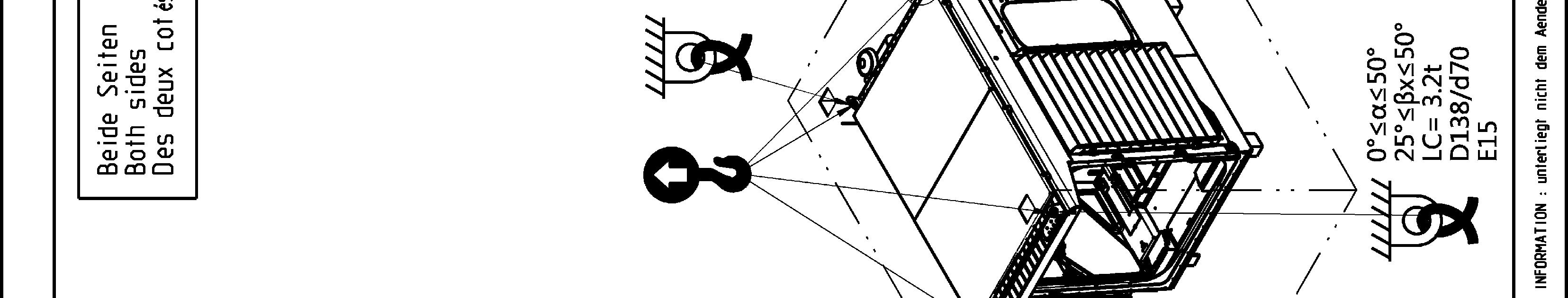
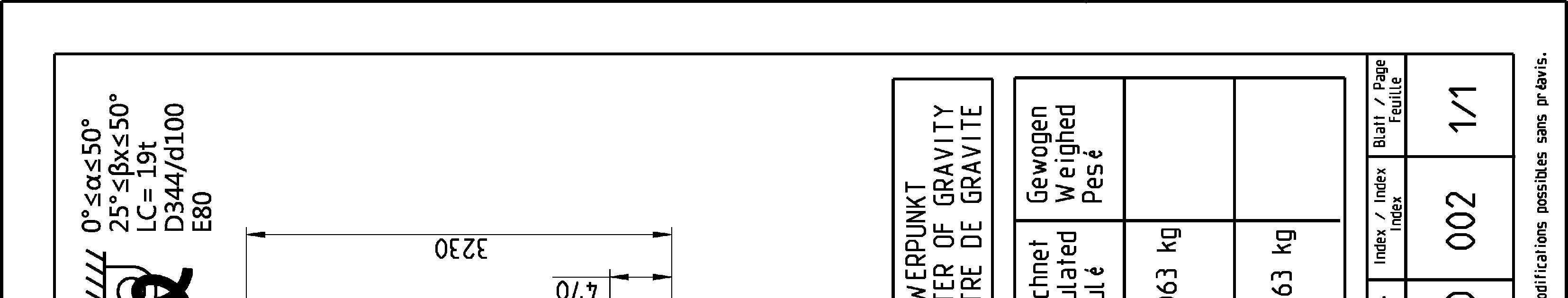
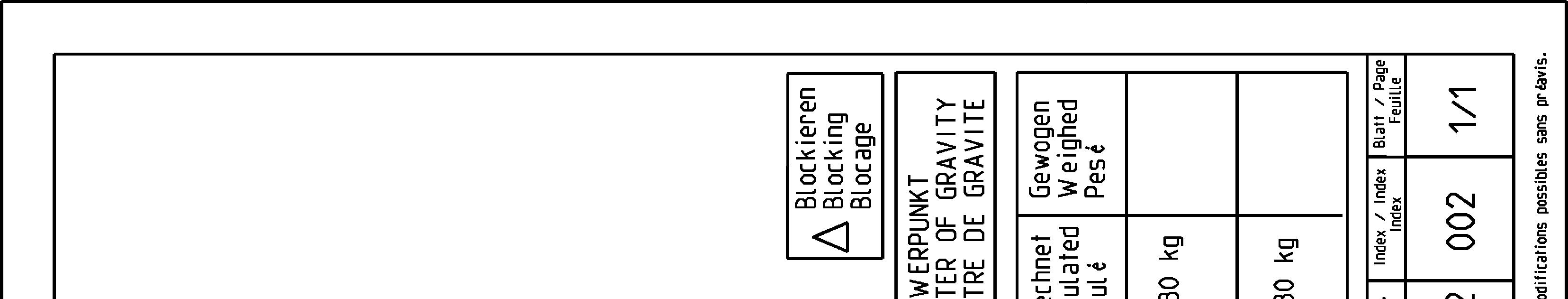
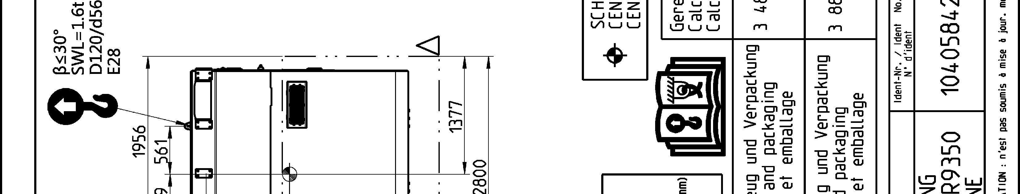
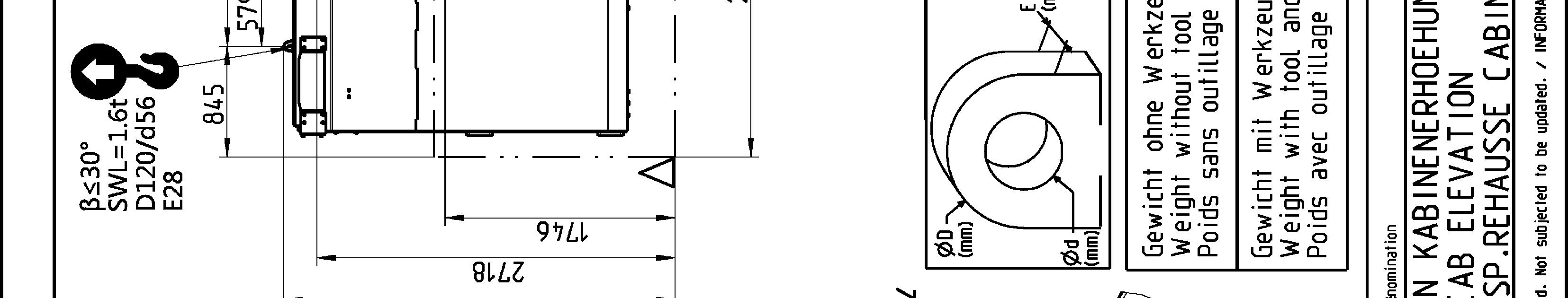
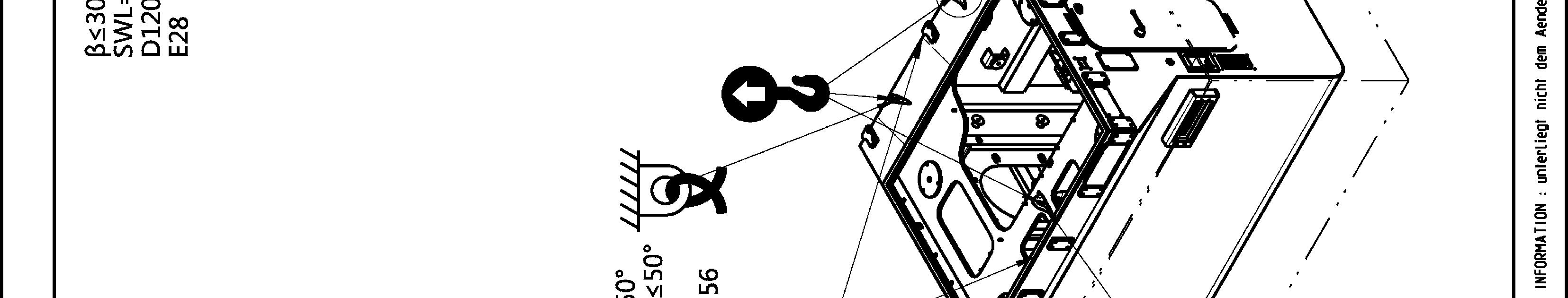
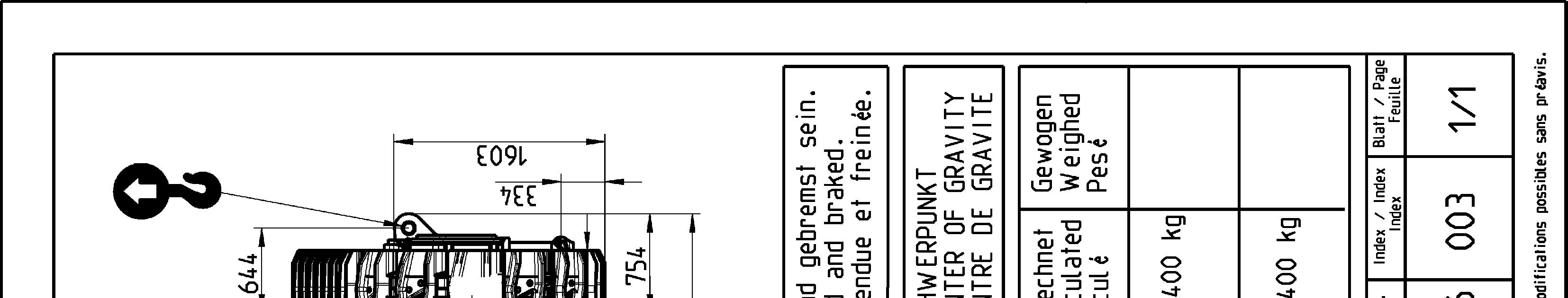
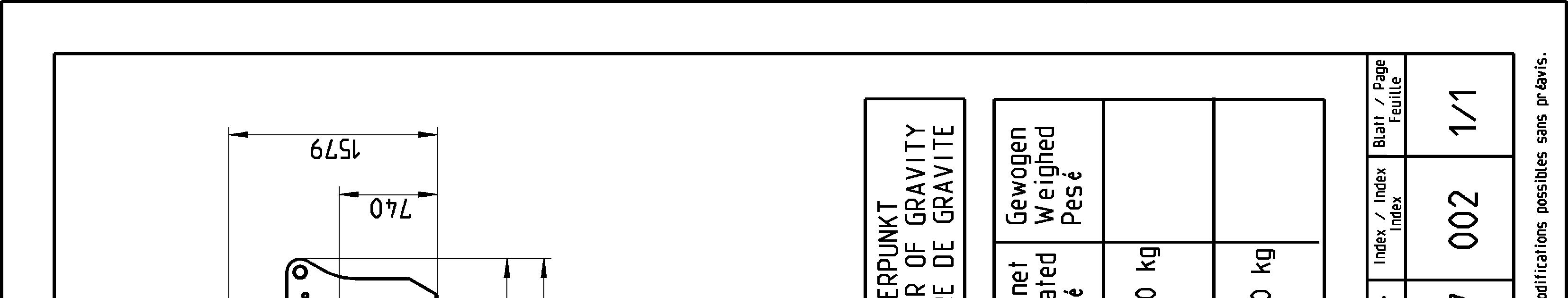
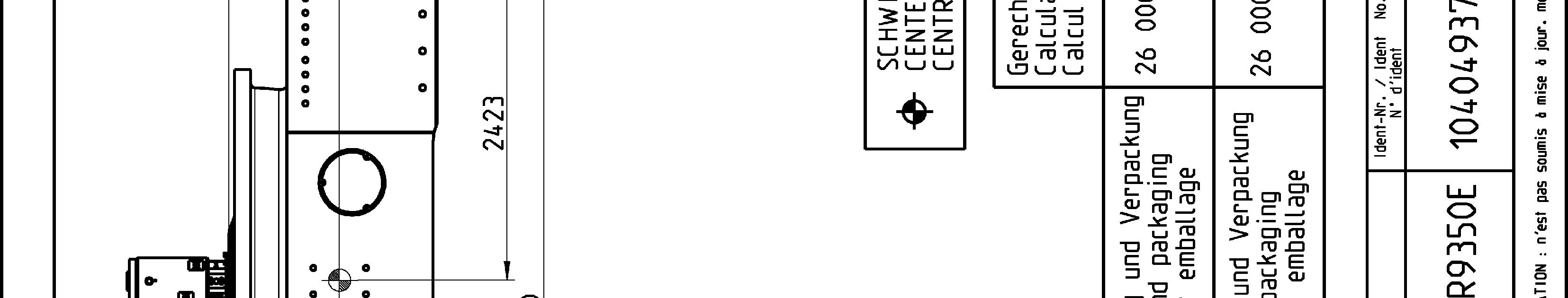
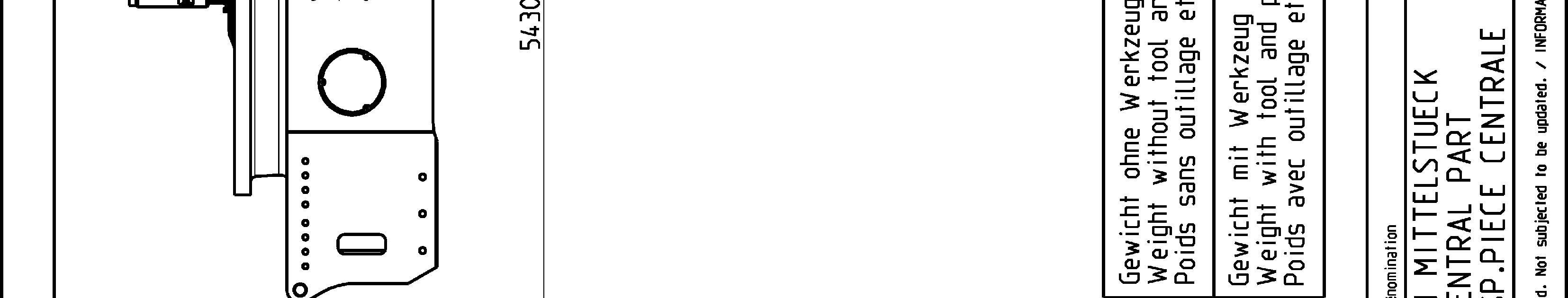
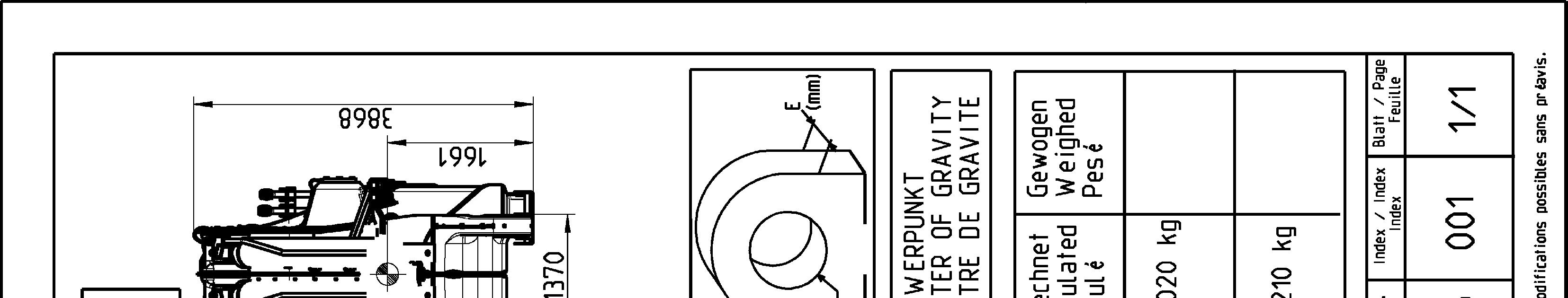
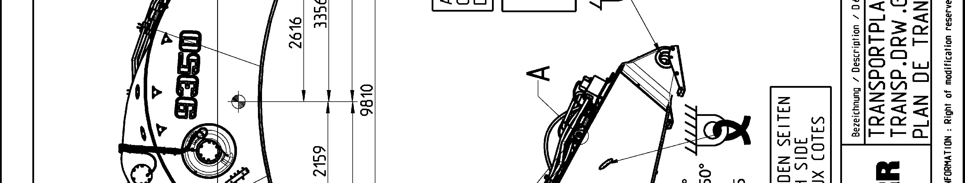
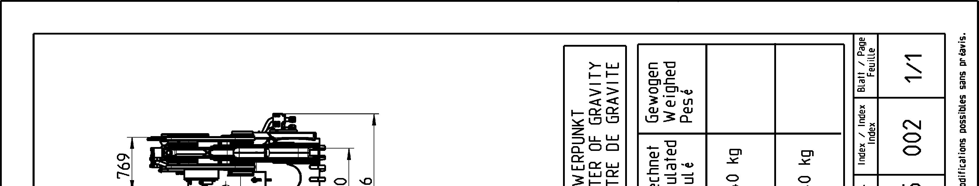
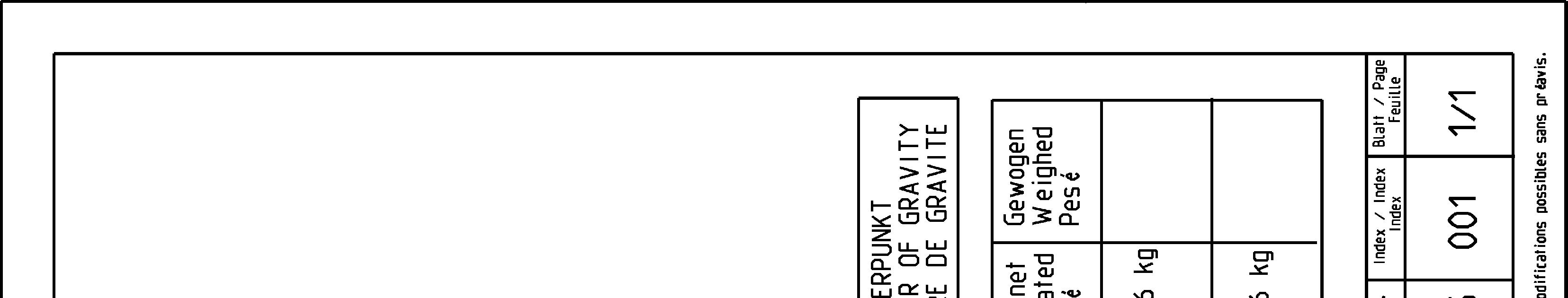
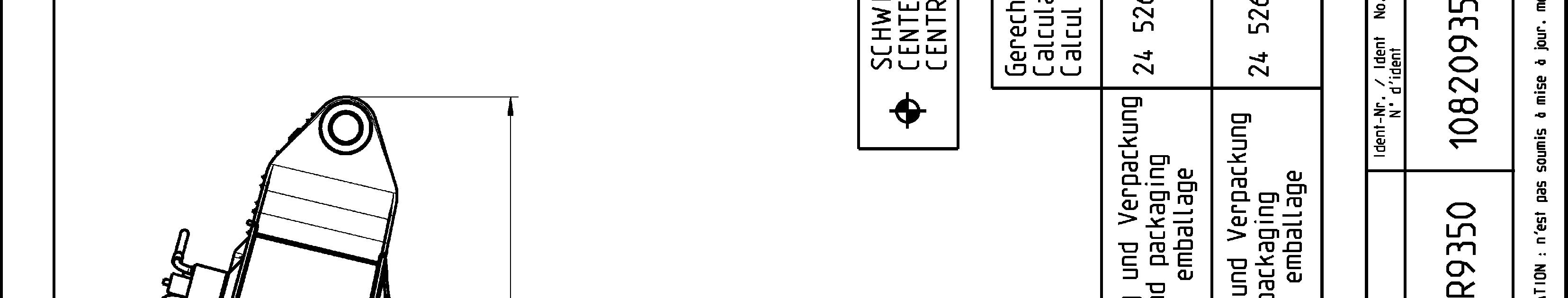
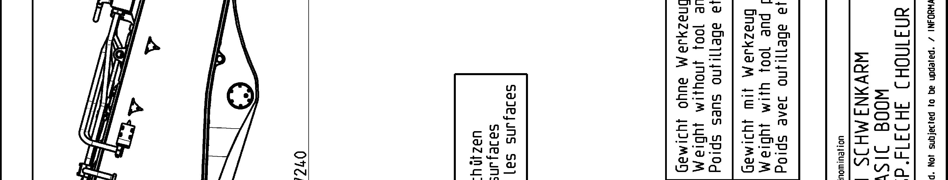
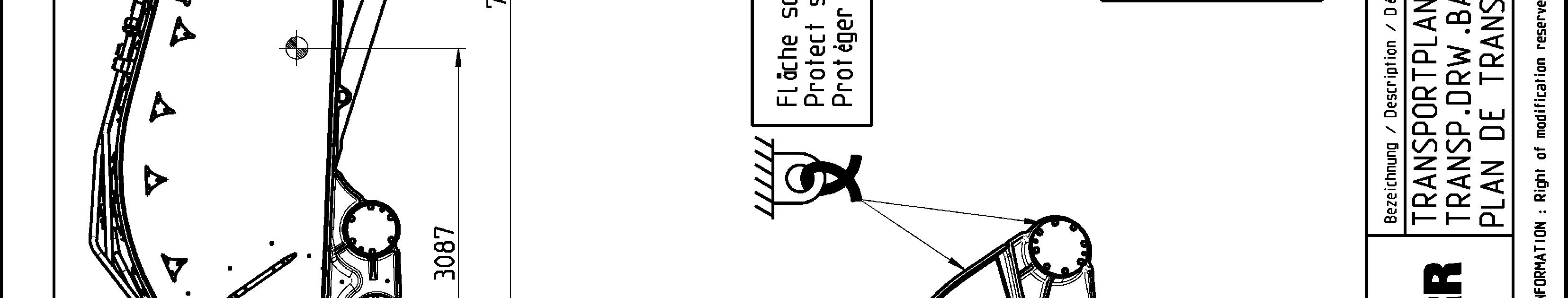
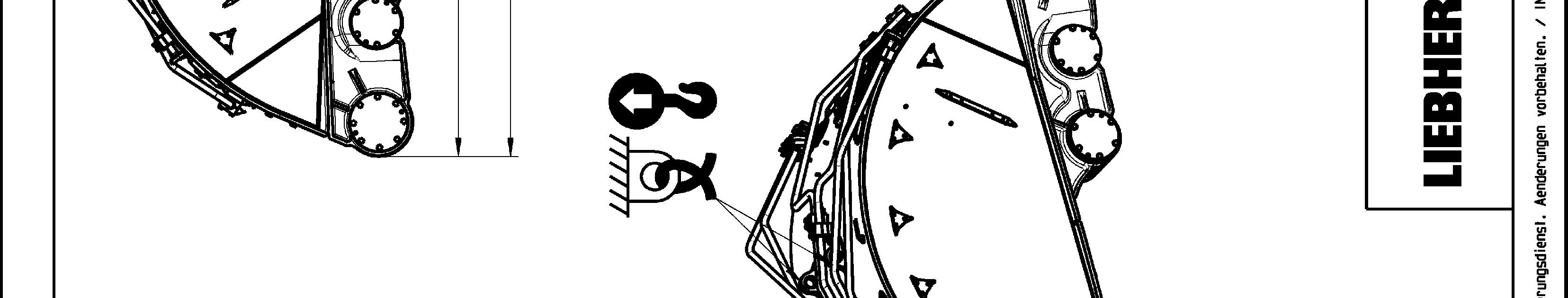
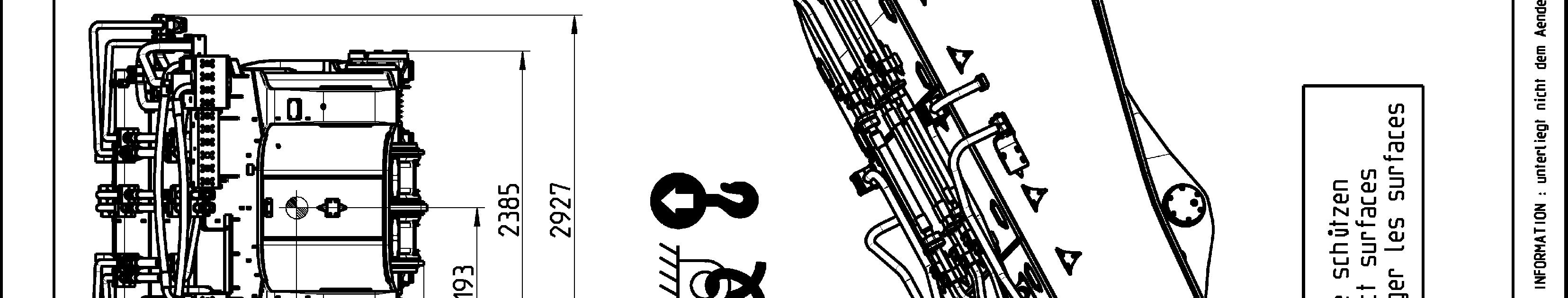
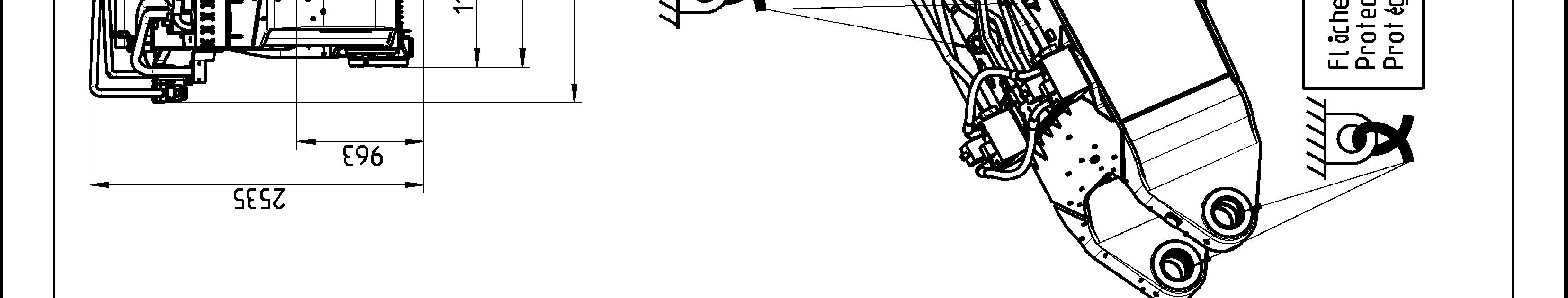
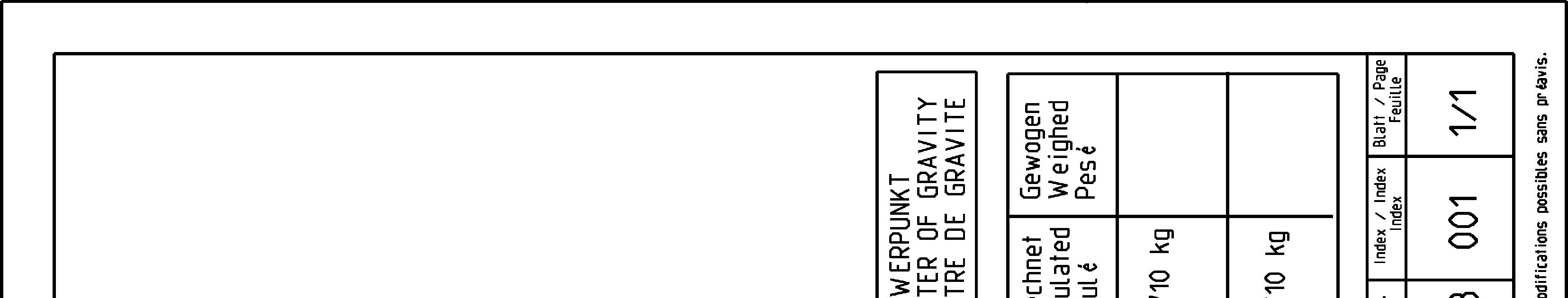
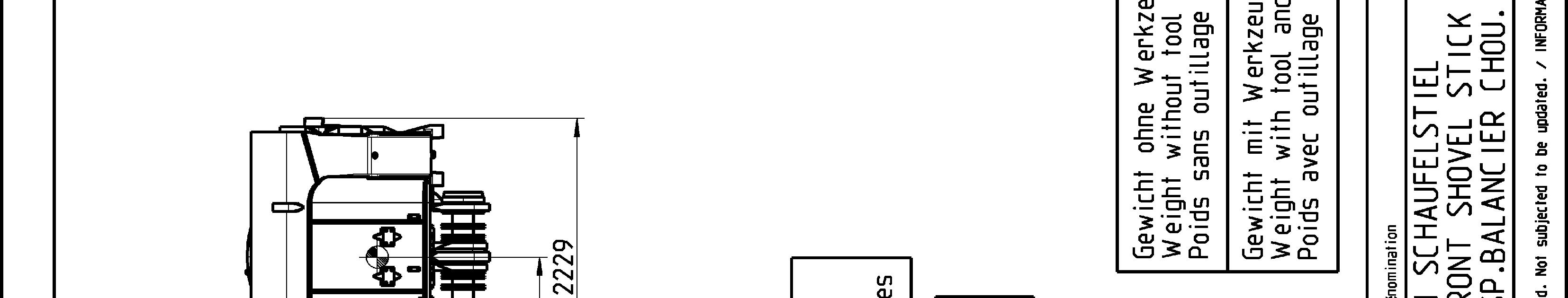
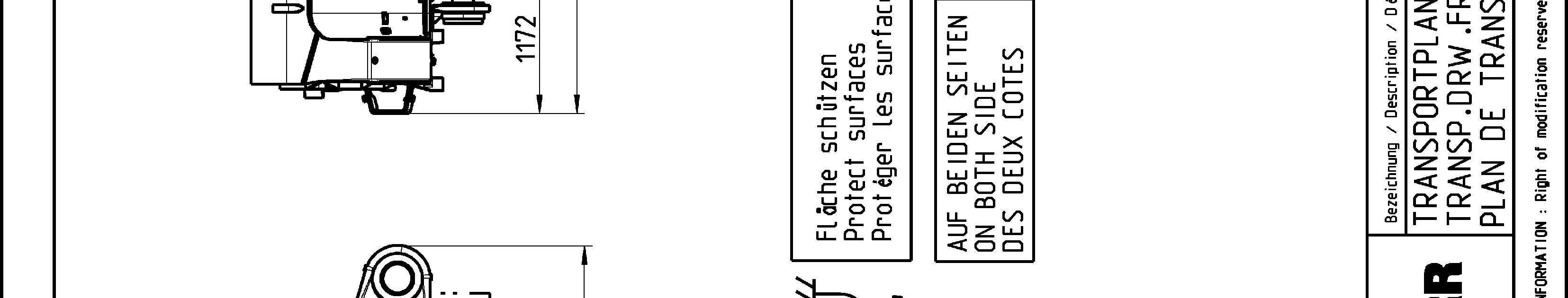
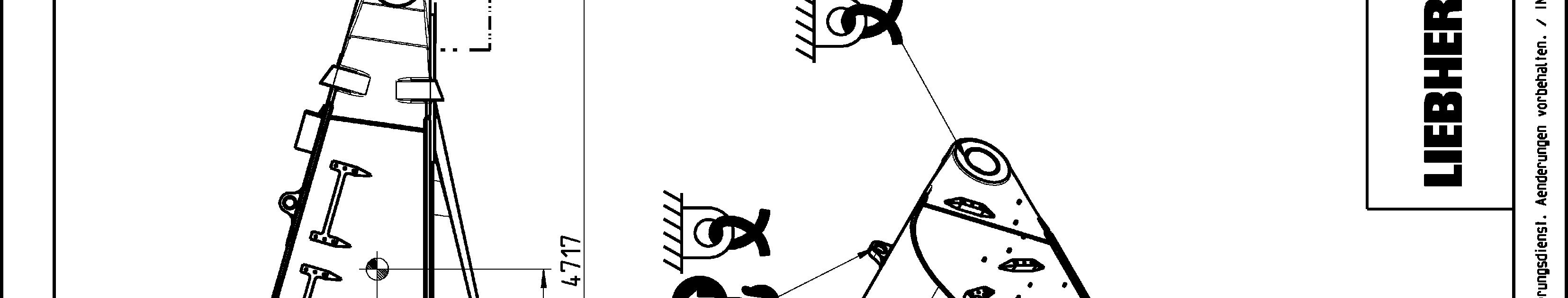
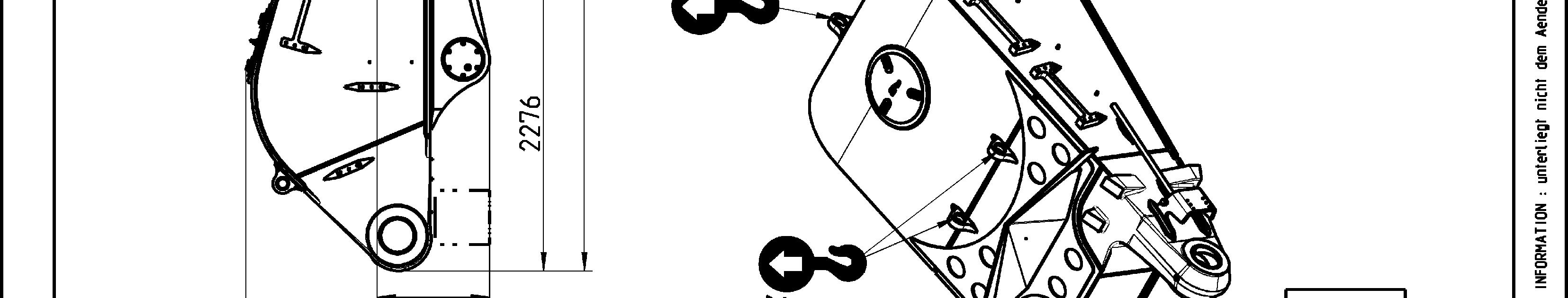
Transport drawings
The following drawings indicate the different lashing and lifting points on the elements of the excavator. Weight (with and without transport tooling and packaging), overall dimensions as well as centerof gravity are also given.
Theaimofthesedrawingsistoensuresafeoperationduringtransport,handlingand storage.
Note!
Thelashingandliftingpointsareindicatedonthe concernedelements oftheexcavator by specific labels (see § "Signs on the machine"). To be easily recognized, lifting points are painted in yellow (in red if excavator is yellow) as well.
Danger!
Theliftingpointsgivenonatransportdrawingforanelementaredesignedtoliftthis element only and nothing else.
Never lift an assembly of several elements by the lifting points of only one of these elements.