8 minute read
Control and operation


Operating and control elements
Disable ladder or trap control lock function
For further information about correct use of this function, refer to § "Access ladder" in section "Entering or leaving the cab" of this manual.
Electric motor and electric systems functions
Forfurtherinformation,refertosection"Settingthemachineintooperation"ofthis manual.
Emergency stop and safetyoperation functions
For further information about correct use of these functions, refer to section "Emergency and safety operations" of this manual.
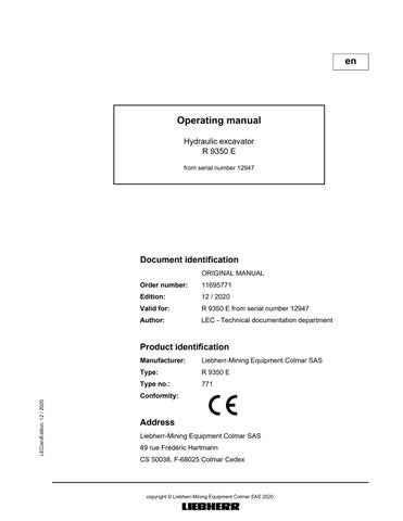
3.1.5Monitoring display
Area A: Diesel engine monitoring
Always off
Area B :Indicator lights

Always off
AreaD: Menu control for screen
The screen can be operated using the following 4 buttons:
S349: Back button
S350: Down button
S351: Up button
S352: Menu* button
* = Change from main to submenus move from page to page.
Area C: Screen
To change the screen contrast:
Press button Menu and arrow button Up (higher contrast) or Down (lower contrast) simultaneously.
The value set will be saved.
To alter the brightness of the main screen:
Press button Back and arrow button Up (brighter) or Down (darker) simultaneously.
The value set will be saved.
Note!
Alightsensorbuiltintothetopleftofthemonitoringscreencontrolstheillumination on the main screen, dependent on the brightness of the environment. Tracking is carriedoutusingthebuttonsandoriginatingfromthebasicsetting.Illuminationwill be automatically reduced in conditions of low environmental brightness.
To change the brightness and the contrast setting to the works setting: Turn off the ignition.
Press and hold the Up and Down buttons simultaneously.
Turn on the ignition again. Release the buttons once the automatic check is completed.
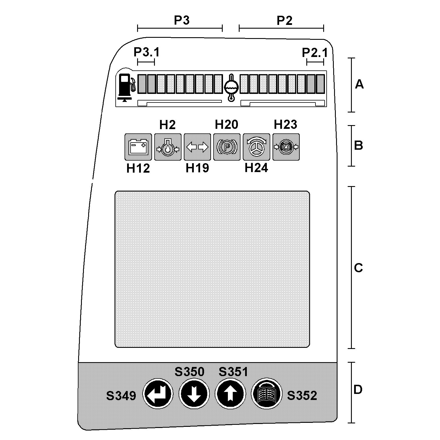
3.1.6Main screen
The main screen appears when the machine has been switched on and remains on displayuntilthescreenischangedovertothemenuselectionscreenusingtheMenu button.
EC
INF Information
Main screen design
SY field
SY Symbols
The upper field of the monitor shows, on the one hand warning and indicator symbols,ontheotherhandaclock,ifnomorethan4warningsymbolsareshown.Should more than two symbols be shown, so the clock is no more displayed and up to four symbols can be displayed simultaneously in the field SY.
Ifmorethan4 symbolsmust bedisplayed, thesymbols willbeshifttotheleft by one symbol every 10 seconds (see section "Warning symbols in the SY field" further in this chapter).
EC field
TheECwindowdisplaystheerrorcodesforelectricalfaultswhichoccur in theexcavator's electronics system (line errors, sensor errors etc.). A maximum of 7error codes are displayed simultaneously. If there are more than these 7 errors present, an arrow which points to where the other error codes are located will be displayed next to the error code window.
Press the Up or Down button. Theerrorcodewindowwillbeshiftedinthedirectionselectedintheerrorcode list.
INF field
The INF field displays information temporarily, in both text and graphic form. If more than 3symbols are to be displayed, the symbols will shift one symbol to the copyright © Liebherr-Mining Equipment Colmar SAS 2020 left approx. every 10seconds.
The information is displayed in graphic or text form and indicates specific operating states on the machine. (see section "Information symbols in the INF field" further in this chapter).
TI field
The machine operating hours and the daily operating hours counter are displayed bottom right in this field.
The® symbol indicates that aquantitylimitationisactiveforthepumps (seesection "Status of hydraulic pumps and electrical inputs and outputs menu" further in this chapter).
Menu navigation in the event of an error display
SY field, the user is returned to the main screen. The relevant error display is activated.
Dependingon theerror(level ofurgency),thebuzzerwillsoundeithercontinuously or in short consecutive bursts. This symbol will be displayed in the INF field.
Danger!
Iftheerrordisplayedisnotrectifiedimmediately,thiscouldleadtopersonssustaining injury or the machine being damaged.
Rectify / have the error rectified immediately.
To switch off the buzzer, press the Back button. The error will be acknowledged and stored.
Warning symbols in the SY field
Each of the symbols which follow will be as Each error which occurs will be stored via the relevant error code.
E548 -E549 – Overheating winding
Thissymbolappearsifthereisaphasefailureofthedirectionofrotation(thewinding number appears in the top corner of the symbol).
E550 - E551 Overheating bearing
This symbol appears when the bearing is overheating (the bearing number appears in the top corner of the symbol).
E506 Oil in splitterbox is overheating
This symbol appears if the oil temperature in the splitterbox exceeds 85°C (185°F). Stop the motor.
Find and correct the problem (splitterbox cooler dirty, ...).
E562 Low oil level in splitterbox
This symbol appears if the oil level drops below the minimum level. Stop the motor.
Find and repair a possible leak. Add oil until the level is correct.
E564 High oil level in splitterbox
This symbol appears if the oil level in the splitterbox is above the maximum level.

Stop the motor.
Find and repair the problem.
It is possiblethat toomuch oilhas been added,ortheoil levelmight have increased due to hydraulic oil entering via a defective pump shaft seal.
E591 Splitterbox oil pressure low
This symbol appears if the splitterbox oil pressure drops below 0.2 bar.
Stop operation and stop the motor.
Find and correct the problem.
Servo pressure low
This symbol appears if the servo pressure drops below 20 bar.
Stop operation and stop the motor.
Find and correct the problem.
E504 Low hydraulic oil level
This symbol appears if the oil level in the hydraulic tank drops below the minimum level. At the same time, the pump are automatically returned to minimum flow.
Stop the motor.
Find and repair the cause of the oil loss.
Add hydraulic oil via the service flap or via one of the return filters.
Hydraulic oil warm-up procedure on
This symbolappears as long asthewarm-upprocedureis on,i.e.as long as thehydraulic oil temperature is below a preset value.
During the warm-up procedure, the main pumps displacement is limited to 50% in order to prevent damage to components.
E505 Hydraulic oil overheat
Thissymbolappearsifthehydraulicoiltemperatureinthetankexceedsapresetvalue.
Stop operation.
Continue to let the motor run and wait until the symbol disappears. If necessary.
Stop the electric motor.
Find and correct the problem (oil cooler dirty, blower or thermostat defective, ...).
E541 – High oil level in travel gear
This symbol appears if the oil level in the travel gear is above the maximum level.
Stop the electric motor.
Find and correct the problem.
Main pumps power reduction on
Thissymbolappearsaslongasthehydraulicoiltemperatureisinapresethightemperature range.
Main pumps power is reduced progressively as long as the hydraulic oil temperature is in this range.
Main pumps output is set to zero if thehydraulic oil reaches the overheating temperature.
Allow the hydraulic oil to cool down to be able to operate the excavator then correctly.
E590 Low hydraulic tank pressure
This symbol appears if the hydraulic tank pressurization drops below 0,15 bar.
Stop operation and stop the motor.
Find and correct the problem (check the air pressure system).
E566 - E567 - E568 - E569 Main pumps are contaminated
This symbol appears if metallic particles have been deposited on the contamination switchof one of the main pumps (the pump number appears in the top corner of the symbol).
Stop operation and stop the motor.
Notify the maintenance personnel.
E572 - E573 Swing pumps are contaminated
This symbol appears if metallic particles have been deposited on the contamination switchofoneoftheswingpumps(thepumpnumberappearsinthetopcornerofthe symbol).
Stop operation and stop the motor.
Notify the maintenance personnel.
E578 - E579 - E580 - E581 Main pumps overheat
This symbol appears if the temperatureononeof the mainpumps exceeds a preset value (the pump number appears in the top corner of the symbol).
Stop the motor.
Find and correct the problem.
E584 - E585 Swing pumps overheat
Thissymbolappearsifthetemperatureononeoftheswingpumpsexceedsapreset value (the pump number appears in the top corner of the symbol).
Stop the motor.
Find and correct the problem.
E 588 - Servo pressure high
This symbol appears if the servo pressure exceeds a preset value. Pumps are automatically set to minimal flow. Stop operation and stop the electric motor.
Find and correct the problem.
E 589 - Servo pressure low
This symbol appears if the servo pressure drops below a preset value. Pumps are automatically set to minimal flow. Stop operation and stop the electric motor.
Find and correct the problem.
E544 External swing teeth greasing
This symbol appears if the swing teeth greasing system is defect.
Find and correct the problem. See also Lincoln servicing manual.
E545 Grease level low
This symbol appears if the grease level drops below minimum level. The bucket will be blocked.
Stop operation and stop the motor. Find and correct the problem. Add grease until correct level is reached. See also Lincoln servicing manual.
Information symbols in the INF field
Service due
This symbol appears if a service interval is due. Switch on the ignition. Theserviceintervaltobecarriedoutwillbedisplayedfor approx.10seconds in place of the overall operating hours.
Acknowledge error
Thissymbolappearsifamachineerror(E5xx)hasoccurredandthebuzzer sounds simultaneously.
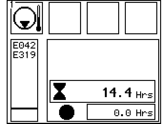
Getting information from the operator’s menu on the main screen
Main screen menu selection
Press the Menu button on the main screen. The list of accessible menus is displayed.
To select the operator’s menu:
Press arrow key Down or Up menu will be displayed on screen with a black background.
The selected menu is displayed with a black background, the Reset daily operating hours menu is used here as an example.
Press the Menu button again. The submenu for the function selected is displayed. Press the Back button again. The submenu will be aborted.
SymbolDescription
Reset daily operating hours counter
Confirm service interval
Selectquantitylimitationrelatingtoattachments(eg.hammer)
Operating hours and device data
Status of hydraulic pumps and electrical inputs and outputs
Recorded and stored errors
Immobilizer (must be activated by LIEBHERR customer service using a service connector)
Reset daily operating hours counter menu
The daily operating hours counter can be reset to 0 using this menu.
Resetting the daily operating hours counter
To set the daily operating hours counter to 0: Press the Up arrow key. The OK which is not crossed out will be displayed with a black background. Press the Menu* button. The operating hours will be reset to 0. ThearrowkeysymbolsUpandDownandtheMenusymbolwillnolongerbe displayed.
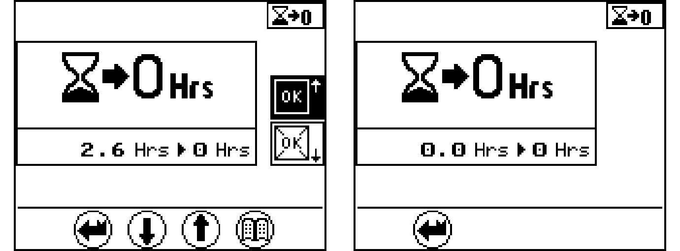
To exit the menu: Press the Back button. The submenu will be aborted.
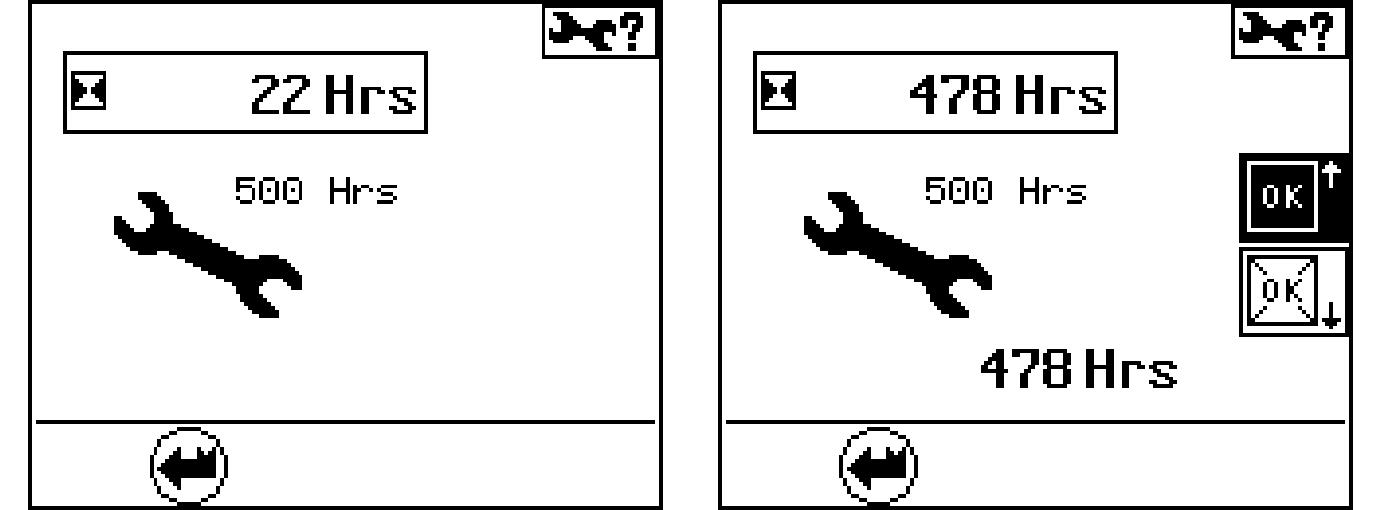
Confirm service interval menu
This menu is used for information on service intervals and to confirm service work which has been carried out.
Apendingserviceintervalcanbeconfirmedamaximumof50operatinghoursbefore the service interval is due.
Whenthistime periodhas beenreached aquery will appear to ask whetherthe service work has been carried out.
Service work carried out. Press the Up arrow key.
The OK which is not crossed out will be displayed with a black background. Press the Menu button. Thecurrentoperatinghourwillbeconfirmedasthelastserviceintervalcarried out.
Service work not carried out.
Press the Back button. The submenu will be aborted.
Allocation of quantity limitation options to external input I1 menu
(Kit input; for example, activation of the hammer pedal)
Predefined quantity limitations have been assigned in this menu. The arrow opposite the symbol represents the current selection. In theexample(seeFig. 3-14),quantity 2 is activeif thespecified attachment is serviced.
Fig. 3-14 Work equipment quantity limitation menu
Press the Up or Down arrow key. A different, predefinedquantity(1-4) canbeassigned (e g.when work equipment is changed). Press the Menu button. The selection is confirmed. The arrow displays the current selection.
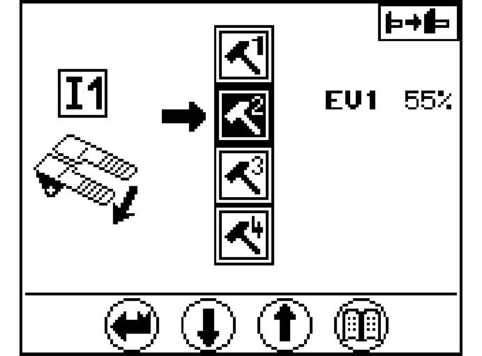
To exit the menu: Press the Back button. The submenu will be aborted.
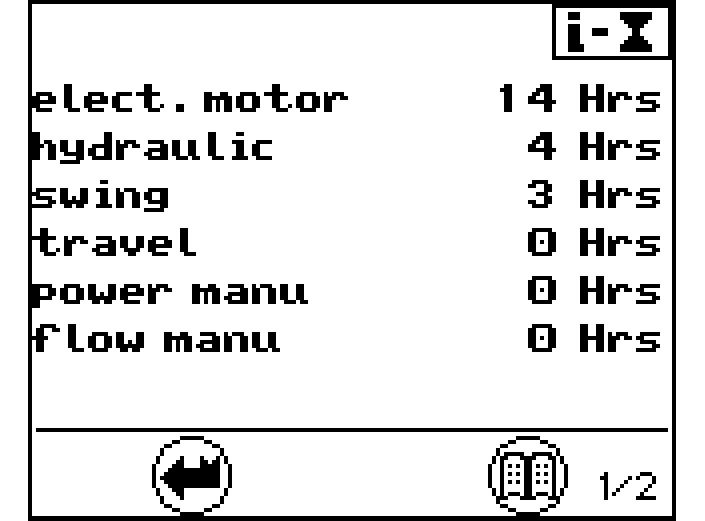
Operating hours menu
Pages1 to2 provideanoverview of theoperatinghours ofindividual units,processes and operating types.
Page 1 provides the service life in hours for:
Press the Menu button. Page 2 is displayed.
The technical data menu, page 2, provides information on :

Press the Menu button again. Page 1 is displayed.
To exit the menu: Press the Back button. The submenu will be aborted.
Status ofhydraulic pumps and electrical inputs and outputs menu
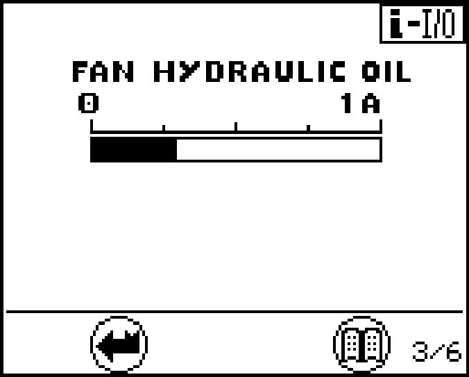
Fig. 3-17 Quantity limitation menu
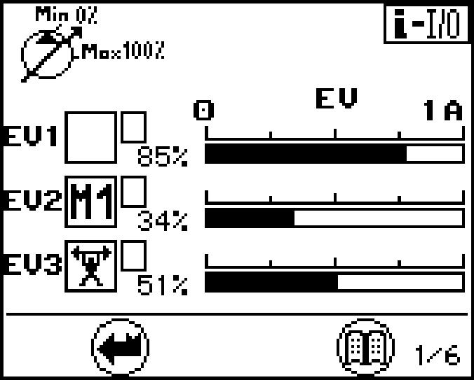
Page1givesinformationabouttheoperatingpositionofthehydraulicpumps.Itgives the following indications for each working pumps :
If the flow limitation is activated for the pump. If it occurs, the symbol "R" is displayed in the field TI, see main screen. The screen 1/6 shows an example with theflowlimitationM1activated,whichlimitsthepumpP2to34%ofthemaximum flow.Shouldseveralflowlimitationsbeactuatedatthesametime,sotheonewith the smallest flow value has priority.
The graphic bar with electric current value indicates for the pump the amount of the momentary flow control signal.
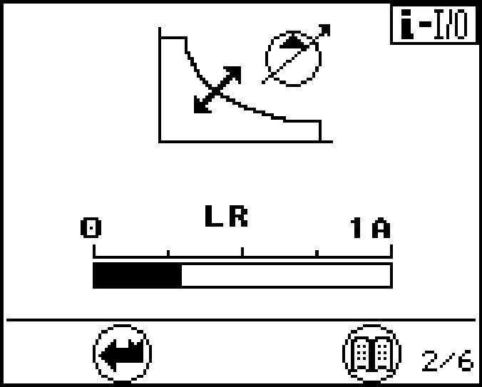
Press the Menu button again. Page 2 is displayed.
The present LR solenoid current (current value for power control) is showed on screen 2.
Fan speed current values menu
Press the Menu button again.