12 minute read
Control and operation


Press the Menu button again.
The second page of the submenu appears.
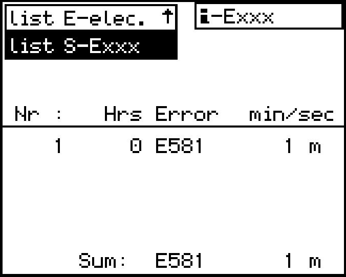
Operatinghoursandthedurationofthefirstandlasttenoccurrencesoftheerrorselected will be listed on the second page.
Press the Back button.
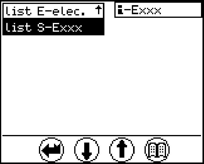
The first page of the submenu appears.
PresstheBackbuttonagaintoselectanothererrortypeorpresstheDownorUp arrow key to select a new error code.
s*: Error was indicated by a buzzer and was acknowledged using the Back button. The duration is given in seconds.
m*: Error was indicated by a buzzer and was acknowledged using the Back button. The duration is given in minutes.
Note!
Only operating errors with an error code E 5xx will be displayed in the list Exxx menu.
Cable error list E-elec.:
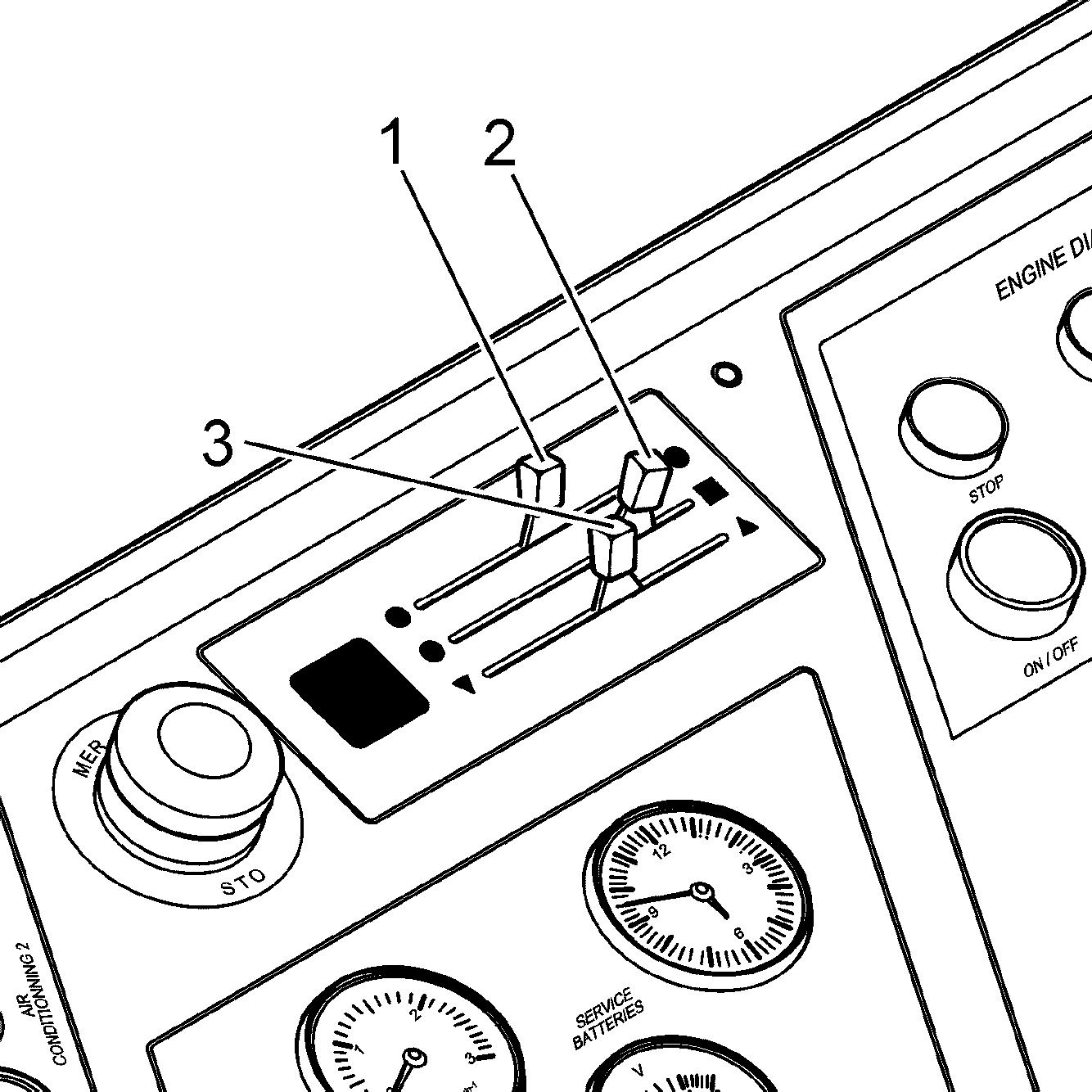
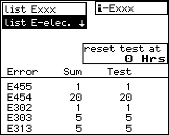
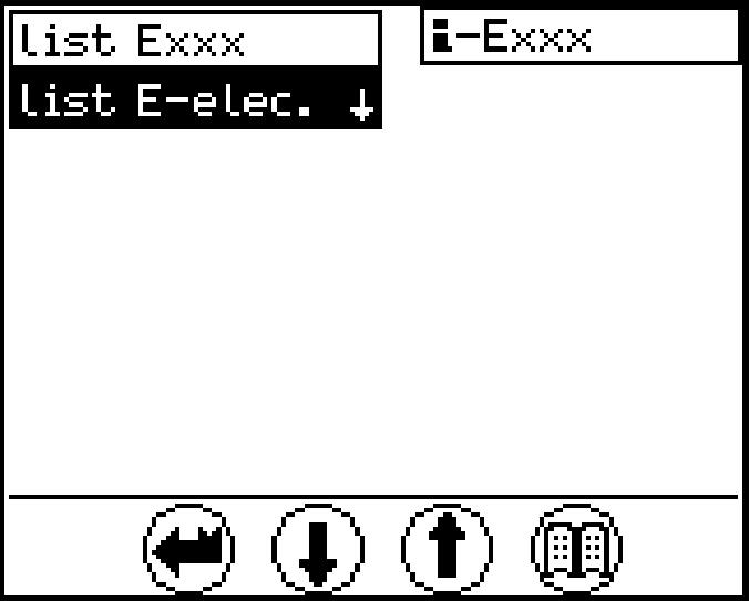
Fig. 3-23 Occurrence of electrical error (Fig. left) and Error statistics (Fig. right)
Select Cable error list E-elec.:
Press the Menu button. The submenu appears.
The column "Sum" shows the number of all errors that were ever noted.
Thecolumn"Test"showsthenumberoferrorsoccurredsincethelastdeletionofthis test error memory listing.
The operating hours above the test column show the operating hour when the last test memory was deleted (reset).
Press the Back button. A different error type may be selected.
Other errors list S-Exxx:
Selecting "list S-Exxx" also shows the errors according to the list in pages (see section "Warning symbols in the SY field" previously in this chapter), but this time only the errors that occurred during "service operation".
For each error, an overview can be shown and paged in just like for the "list-Exxx" selection. The column"Sum" shows the number of all errors that were ever noted.

3.1.7Monitoring cameras
1
System description
Monitoring cameras are installed on the excavator as follows in order to extend the posite side of the cab,
Display
The inputs from the different cameras are transmitted to the display located on the front right of the cab and divided on the screen as described above (see Fig. 3-25).
copyright © Liebherr-Mining Equipment Colmar SAS 2020
Full screen
Fig. 3-26 Full screen display
The input from one camera can be switched to full screen (with the input from the other camera remaining simultaneously displayed with normal size).
To switch acamera to full screen: Press F1.
Camera 1 is switched to full screen while camera 2 remains displayed with normal size.
Press F2. Camera 2 is switched to full screen while camera 1 remains displayed with normal size.
To switch back to standard display: Press F8
Screen turns back to standard display.
Note!
Additionalcamerascanbeinstalledasoptionalfeature.Inthiscase,theadditional inputs will be displayed on the screen on the remaining free fields and full screen display will be possible via corresponding Fx button.
3.2The access and the outfit of the cab
Safely getting up
chine on even, horizontal ground. The upper structure should be positioned with the undercarriage in such a way that the steps and ladders are aligned with each other.
(grips)areingoodcondition.Inparticular, you should ensure that they are free of dirt, oil, ice and snow.
NOTE:Toensurethatthedoorsopenproperlyinallweatherconditions,thedoor seals must be dusted with talc or silicon at least every two months or more often if required. The door hinges and locks should be greased regularly.
two hands and one foot or two feet and one hand must always be in contact with the access system at the same time.
fore you climb any higher. External influences, such as wind, can make it more difficult to open doors. Because of this, always use your hand for control when opening doors. Ensure that the door is latchedopen to prevent it slamming open and shut.
icularly vigilant to realise the climbing and descent from the cab with the best safety conditions, and do or give the instructionstotheexecutionofpriorpreparations tobeaccomplished,asenunciated above, in order to displace yourself safely.
still using the three-point support andsit downinthe and close it immediately using the door handle, before tilting down the safety lever, and start the machine. isnecessarytofastenyoursafetybelt. If unavailable, let it be installed before working with the door open. hethree-point support and closethe door as soon as you enter the cab. esafetybelt(ifavailable)beforetilting down the safety lever, and start the machine.
Safely getting down
install yourself.
sitioned with the undercarriage in such a way that the steps and ladders are aligned with each other.
locking. Take care ofweatherconditions ! Unfasten the safety belt.
the machine when getting out and use three-point support, i.e. two hands and one foot or two feet and one hand must always be in contact with the access system at the same time. Climb down until youcanclosethedoorssafely.Alwaysuseyourhandforcontrolwhenclosingthe doors. Lock the door.
3.2.1Entering or leaving the cab Climbing up Caution!
Entering or leaving the cab incorrectly could lead to injury.
Proceedwiththesameattentiononexitorentryofthecab,aswhileclimbingthe machine.
Ensure that the safety lever is always in its highest position when entering or leaving the cab.
Alwaysusethehandholdsprovidedforthepurposewhenenteringorleavingthe machine.
Facethemachinewhengettinginoroutandalwaysusethree-pointsupport,i.e. twohandsandonefootortwofeetandonehandmustalwaysbeincontactwith the access system at the same time. Never use the control elements as handles. Never jump from the machine.
Getting in climb up on the machine.
Climbinwiththeaccessladdersandwithyourfacetowards theladdersanduse the provided handholds. On the cabin catwalk, open the door. Adjust the seat if necessary.
Getting out
Switch off the machine and pushthe safety lever up.
Control and operation
The accessand theoutfit of the cab
Open the door fully.
Go out of the cabin on the cabin catwalk. Close the door.
Godownwithyourfacetowards theladders,andusetheappropriatehandholds.
Access ladder
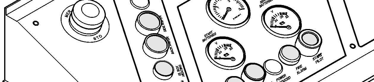
Depending on the machine, there are two types of access ladder control box:
H67 Control light red / ladder not up S155 Push-button / access ladder up H68 Control light red / ladder not locked (only for the rotating access ladder)
S156 Push-button / access ladder locking (only for the rotating access ladder)
S125 Switch / lighting of cab access S157 Push-button / access ladder unlocking (only for the rotating access ladder)
S141 Switch / lighting of main ladder S158 Push-button/accessladderdown
3-29S122 on control board
Theaccessladdercanbebroughteithertolowerpositiontopermitaccesstotheuppercarriage or to upper position during operation. Before operating the machine, the ladder must be fully raised to the uppercarriage and locked in place.
Theladdercanbeextendedandretractedfromtheuppercarriageviathecontrolbox E1022-1,whichisinstalledonthecatwalknexttoupper laddersectionleadingtothe cab.
Danger!
Neveractuatetheladderifyouorathirdpersonareonorinimmediateproximityof the ladder.
To bring the ladder into lower position: For the 45° access ladder
Pushtheswitch S158toswingtheladder until ithas reachedthelowestposition. For the rotating access ladder
Pushtheswitch S157 tounlock theladder (theredindicatorlight H68 willgoon). Pushtheswitch S158 toswingtheladder until ithasreachedthelowestposition (the red indicator H67 is on).
To bring the ladder into upper position (working position): For the 45° access ladder
Push the switch S155 until the ladder has reached its top position. When the top position is reached, the ladder is locked and control light H67 goes out.
Caution!
For safety reason, the excavator can only be operated if the ladder is locked in its top position. Otherwise, the red indicator light goes on. This means that the swing and travel movements remain locked.
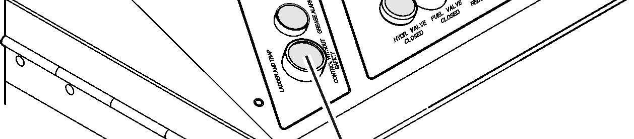
Thissafety measurecan bemomentarilyby-passedby pushing andholdingthebutton S122 on the control board.
Note!
The ladder can only be swung up with the Diesel engine running.
For the rotating access ladder
Push the switch S155 until the ladder has reached its top position. When the top position is reached, the ladder is locked and control light H67 goes out.
Pushthe switch S156 to locktheladder (whenlockedthe red indicator light H68 goes out).
Caution!
For safety reason, the excavator can only be operated if the ladder is locked in its top position. Otherwise, the red indicator light goes on. This means that the swing and travel movements remain locked.
Thissafetymeasurecan be momentarilyby-passedby pushing andholdingthebutton S122 on the control board.
Theladdercanonlybelockedafterithasreacheditsupperstopposition(H67isoff). Theladdercanonlybeswungupordownwhenthelockingdeviceisinunlockedposition (H68 is on).
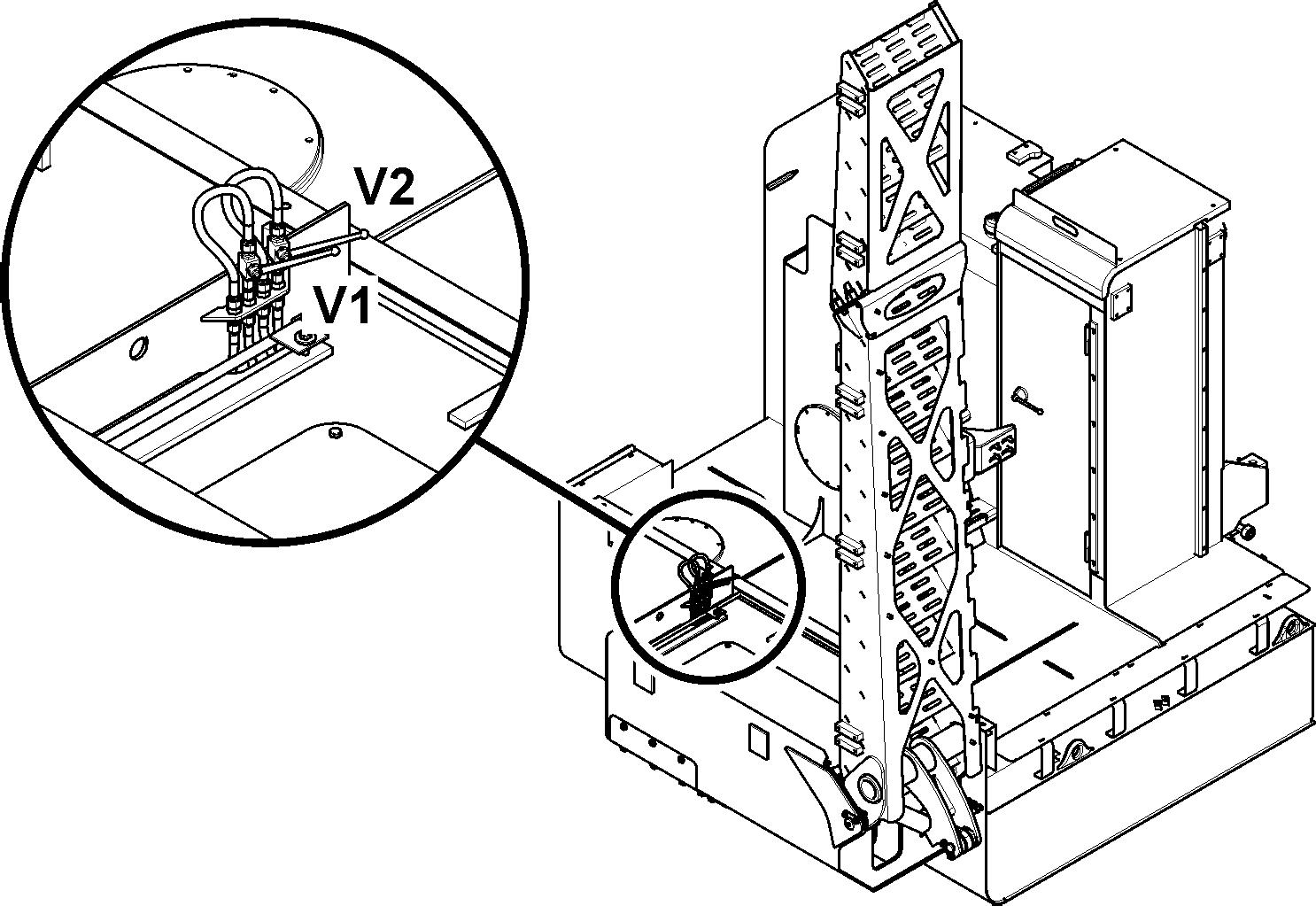
To bring the 45° access ladder into lower position in case of emergency:
In case of defect (servicebatteries outof order, defective solenoid valve or wiring...) avoiding the regular lowering procedure of the ladder, Open valves V1 and V2 to lower the ladder.
If an emergency stop is operated, the ladderis lowered automatically.
3.2.2Safety lever
For safety purposes, the left control panel is provided with a safety lever.
Caution!
The safety lever must always be pushed up into its highest position (see arrow) when entering or exiting the cab.

When the safety lever is pushed up, the pilot control circuit is disconnected. This means that: stick or foot pedals, are operated. locked (LED in switch S17 illuminates). S17
When the safety lever is pushed (push up / push down) to its lowest position, the slewing gear brake and the LED in switch S17 will return to their original states and the pilot control devices will be active.
Before the operator starts working, he must push the safety lever down into its
3.2.3Operator’s seat
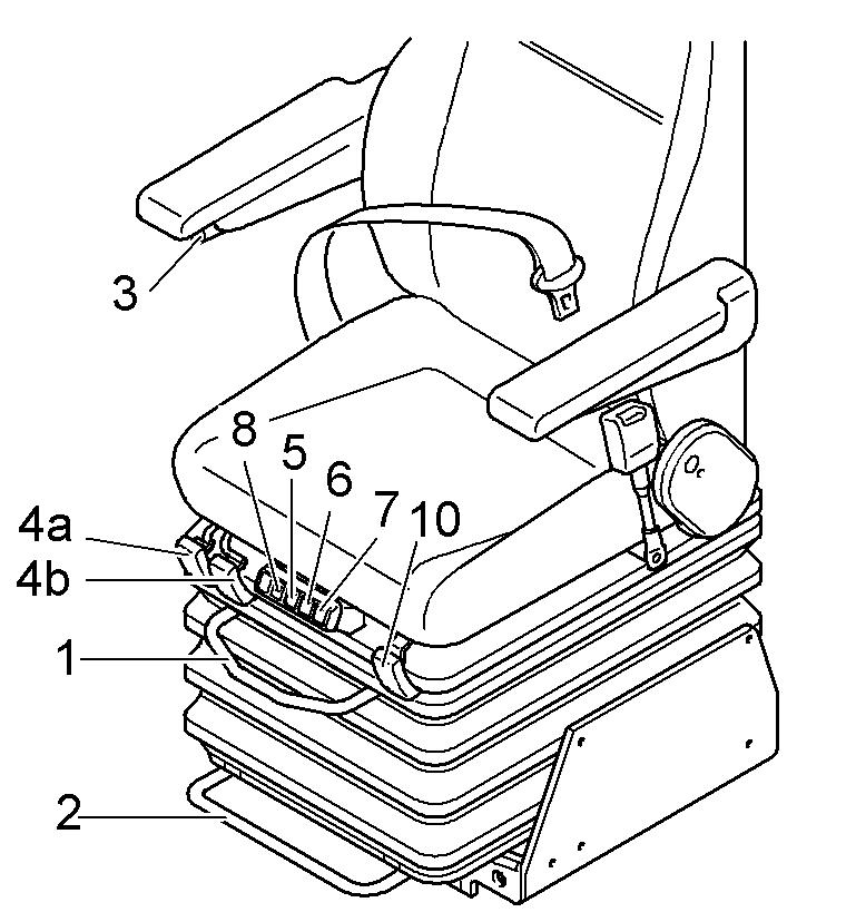
The accessand theoutfit of the cab
1 Set horizontal, upper 4a Set seat inclination, front 7 Set lumbar support
2 Set horizontal, lower 4b Set seat inclination, rear 8 Seat heating
3 Adjust armrests 6 Set lumbar support 10 Set backrest starting the machine; this means that:
This will avoid unexpected movement of the machine.
Setting the armrests
Turn the knurled head screw 3 on the armrest in direction a The armrests incline upwards.
Turn the knurled head screw 3 on the armrest in direction b. The armrests incline downwards.
Setting the seat and backrest
Rear seat inclination: Pull lever 4a up, set the inclination and release the lever.
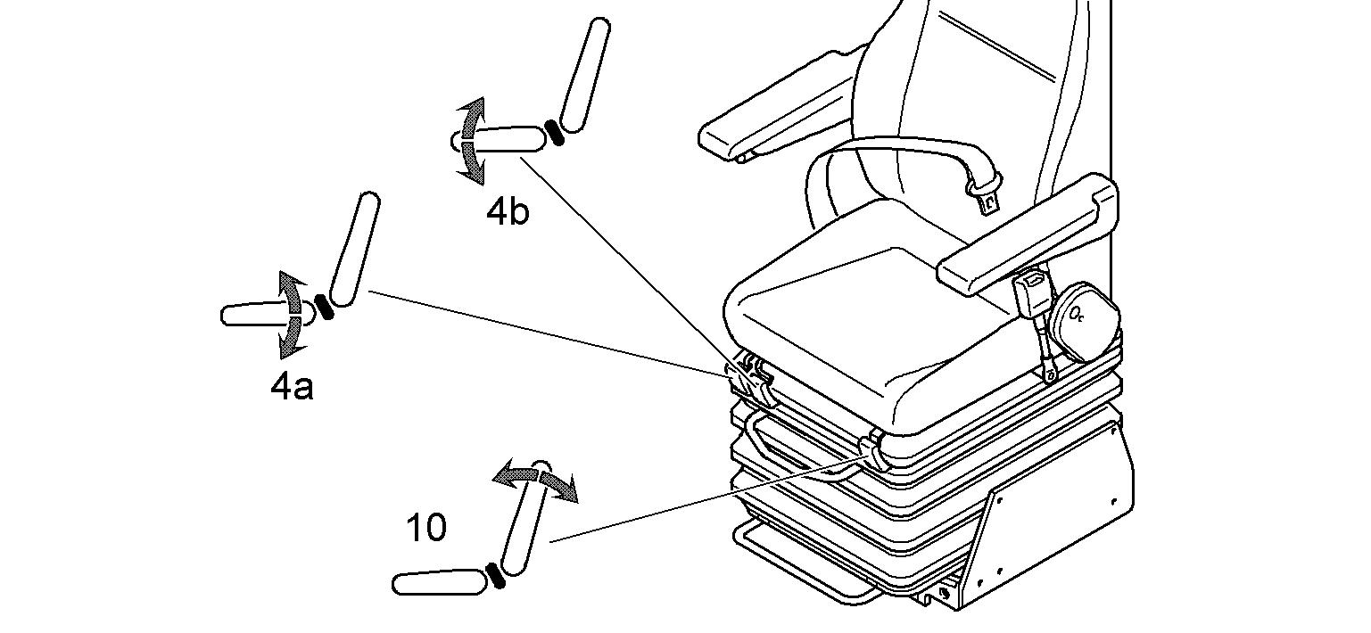
Front seat inclination: Pull lever 4b up, set the inclination and release the lever.
Backrest: Pull lever 10 up, set the inclination and release the lever.
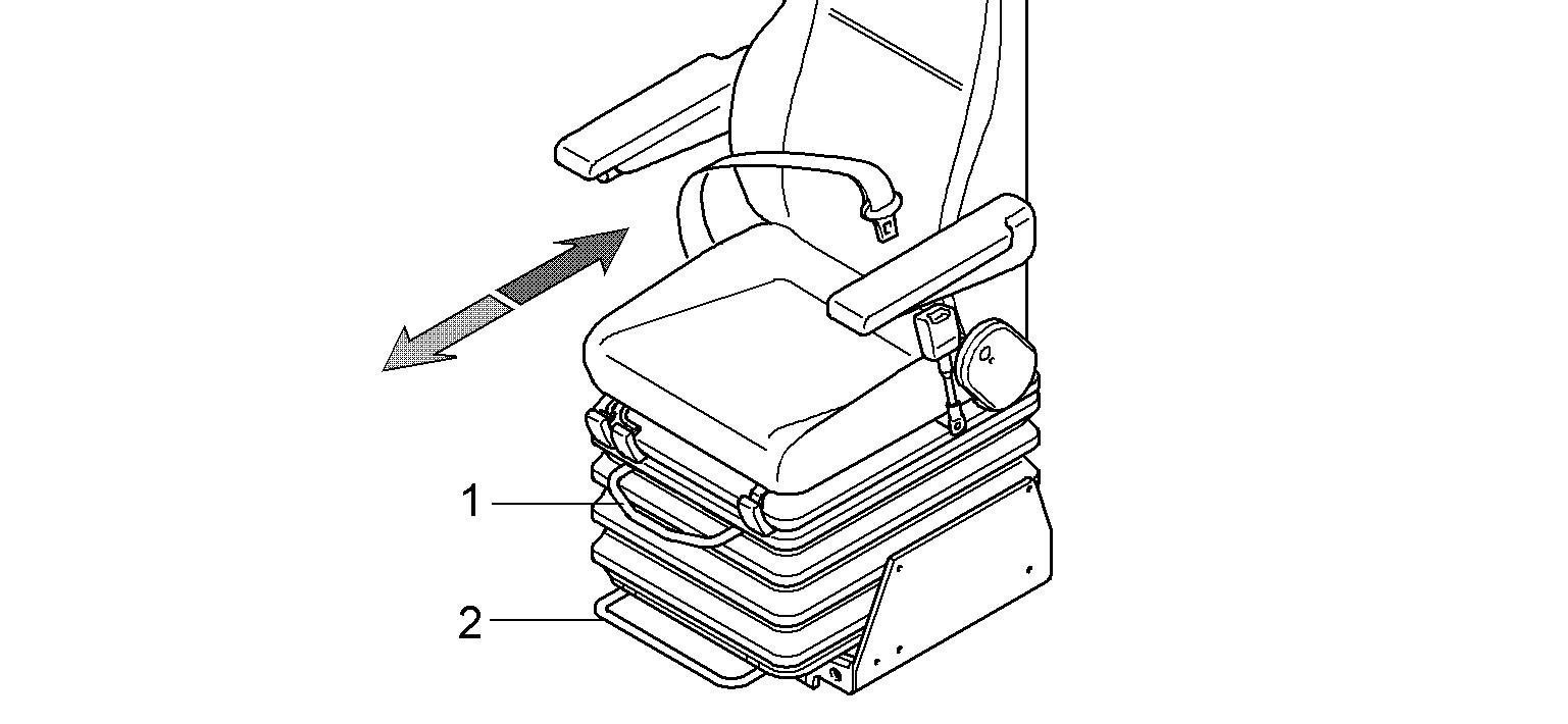
Setting the horizontal seat position
Pull up the lever 1 to push the operator's seat in the horizontal direction. Pullupthelever2topushtheoperator'sseatandcontrolpanelsinthehorizontal direction.
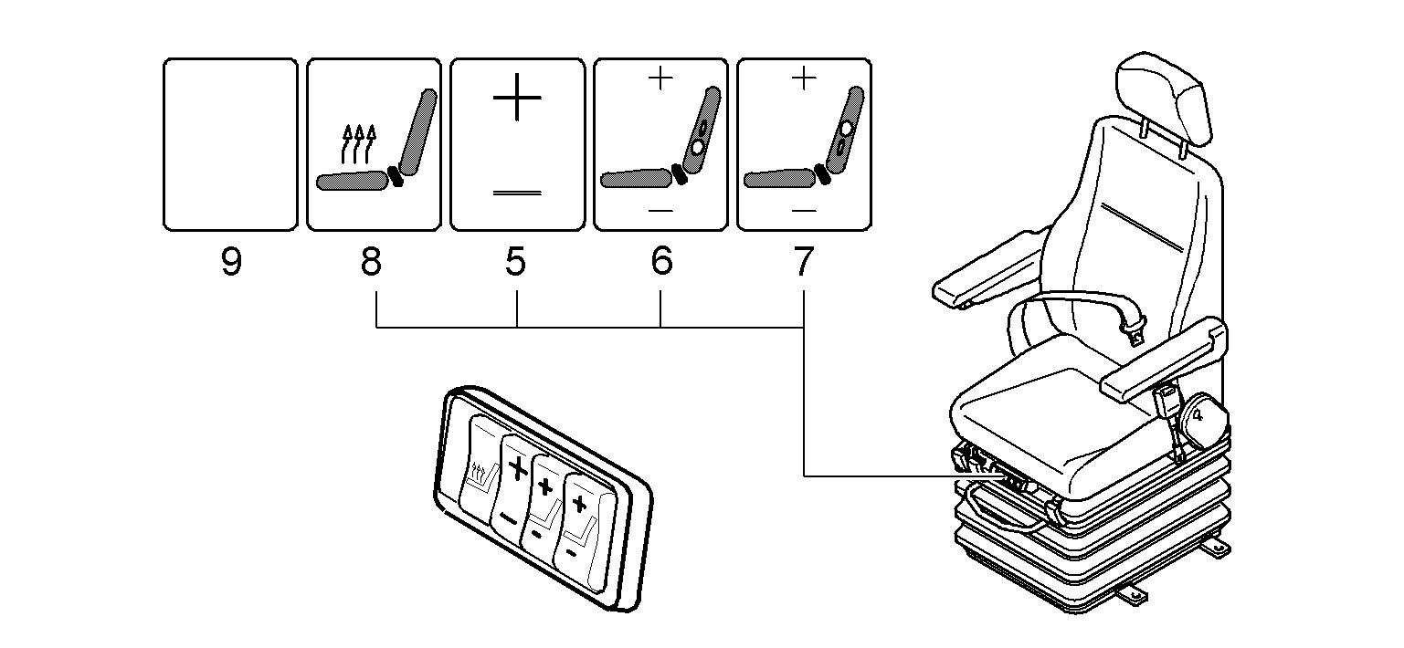
Setting the vibration damping and lumbar support, switching on theseat heating (air-cushioned operator’s seat, optional extras)
To set the vibration damping: Press button 5 (+ or -) and set the vibration system according to body weight.
To set the lumbar support: Press button 6 (+ or -) to inflate or deflate the lower lumbar chamber. Press button 7 (+ or -) to inflate or deflate the upper lumbar chamber.
To set the seat heating: Use switch 8 to switch the seat heating on or off. The seat heating switches off automatically when the temperature set is reached.
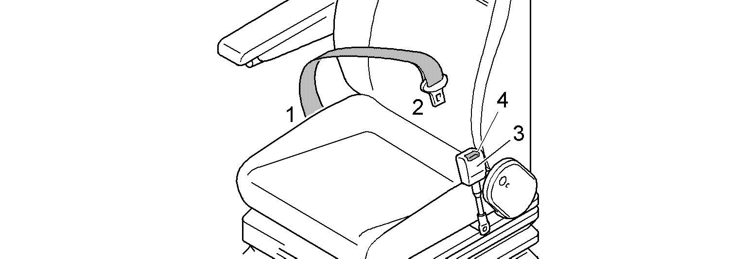
Putting on / releasing the safety belt
The safety belt is automatic. It is not necessary to adjust the length of the belt. Pull the belt and buckle 2 out of the roller mount 1 If pulled out of the roller mount sharply, the belt may lock. Push the buckle into the belt lock 3 until it fastens.
The access and the outfit of the cab
Danger!
The safety belt is designed to protect the operator. Before starting the machine, always fasten the safety belt. Ensure that the safety belt is not twisted when it is fastened. To ensure your safety, check the condition, function and fastening of the belt regularly and replace any damaged parts without delay.
To open lock 4, push down on the belt lock using yourthumbs. The safety belt will slide automatically back into the roller mount 1.
3.2.4Adjusting of the auxiliary seat
Thelever 1servestolocktheauxiliaryseatin
To rotate the seat, Pull the lever 1.
To seat, Pull down the seating.
Note
When there is no oneon this auxiliary seat, the seating must be pulled up andthe
3.2.5Sunshade
Thecabisprovidedwiththreesunshades,locatedonthewindscreenandonthetwo side windows.
Windscreen
Pull the sunshade down using the cross strut on the sunshade 1. The sunshade can be set for individual use.
Pull out on the string 2
The sunshade rolls itself up.
Side windows
Pull the sunshade down using the cross strut on the sunshade 1 The sunshade can be set for individual use.
Pull out on the string 2
The sunshade rolls itself up.
The access and the outfit of the cab
3.2.6Emergency exit
Rear emergency exit (if installed)
Danger!
Incorrect use of the emergency exit! Risk of death.
Youcanusethewindowatthebottomofthecabdoorasanemergencyexitonly if this window has an emergency handle. Ifthewindowatthebottomofthecabdoordoesnothaveanemergencyhandle, use the lateral emergency exit (refer to the description below).
To open the emergency exit: Pulltheemergencyhandle1 ontheinsideofthewindowwhichisinstalledatthe bottom of the cab door.
The window seal breaks into two parts and the window is released. Push the window out.
Lateral emergency exit
You can use the rear left window of the cab as an emergency exit.
To open the emergency exit:
If the rear left window has an emergency handle: Pull the emergency handle on the inside of the window. The window seal breaks into two parts and the window is released. Push the window out.
If the rear left window does not have an emergency handle: Breakthewindowwiththeemergencyhammerwhichisinstalledbetweenthetwo left windows of the cab.
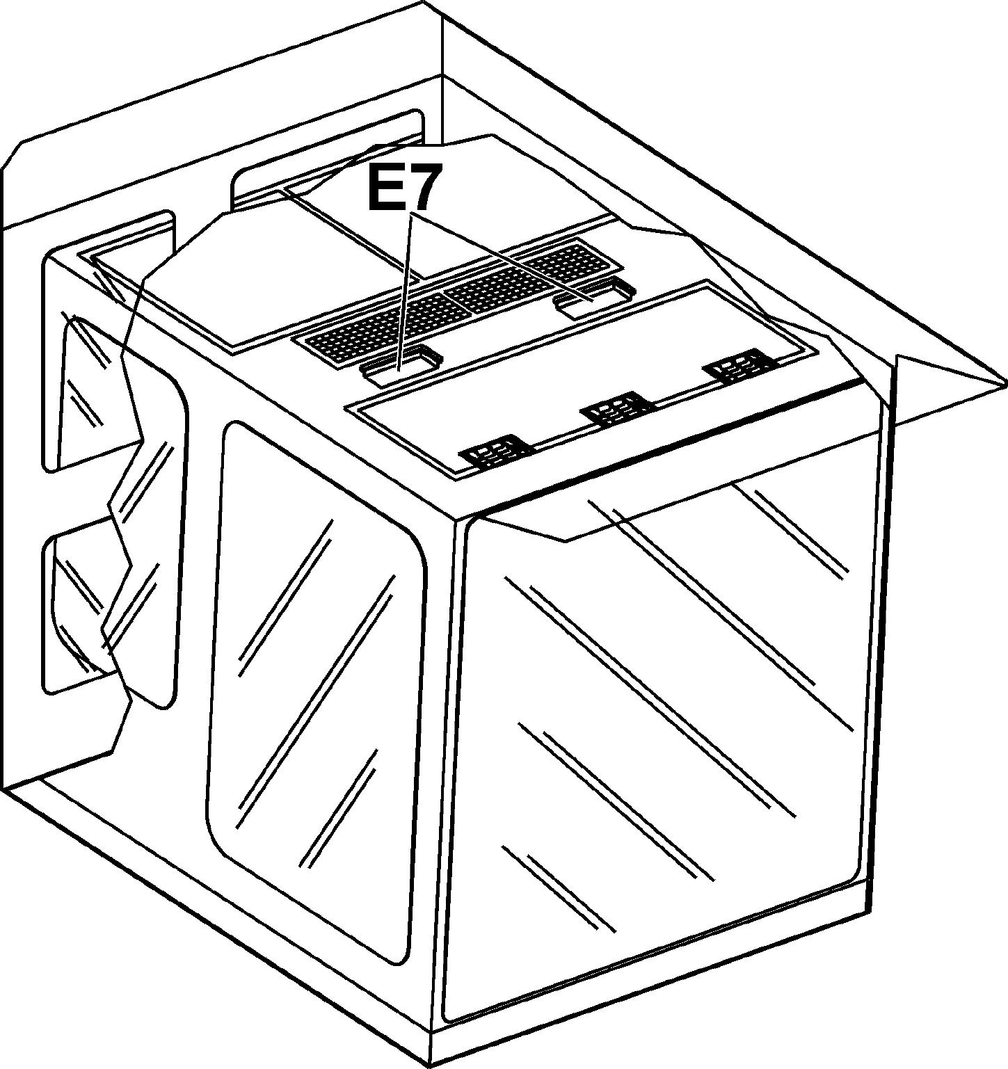
3.2.7Interior lightings
The interior lightings are switched on using the switch S41 on the Keypad. Press the switch S41 The lights E7 areswitched on. Press the switch S41 again. Interior lighting E7 are switched off.
3.2.8Fire extinguisher
Theinterior ofthe cab is fitted with fixing points allowingthemounting of a fireextinguisher. These fixing points are on the right side wall of the cab, on the frame between the two windows.
Note!
It is the responsibility of the owner of the machineto decide if it must befitted with a fire extinguisher or not, considering the operating conditions and the regulations which apply in the country and at the point of use of the machine.
Caution!
If your machine is fitted with a fire extinguisher: Always comply with the operating guide on the body of the extinguisher, Make sure, all the inspections of the fire extinguisher which are prescribed by the regulations applicable to the operating place of the machine are accomplished.
3.2.9Windscreen wiper
Windscreen wiper
When the ignition is switched on, pressing switch S14 will activate the windscreen wiper.
Press switch. Intermittent switching LED I in the switch illuminates. Press switch again. Continuous operation. LED C in the switch illuminates. LED I in the switch goes out. Press switch again. Windscreen wiper isswitched off. LED C in the switch goes out.
Setting the interval time for the intermittent switching
The interval time can be set when the ignition ison by pressing switch S14. Pressthe switch until the windscreen wiper is switched off (LED Iin switchgoes out)
Press and hold switch. LED I in the switch flashes.
Release the switch when the desired interval time has been reached. The interval time can be set to between 2 and 10 seconds.
Windshield washer installation
When theignition is switched on, pressing button S11 will activate the electric windscreen washer installation.
Press and hold button.
Washingwaterwillbesprayedontothewindscreenthroughtheoutletnozzles. The windshield washer runs continuously. Release the button.
Washing water will be stopped. Windshield washer will run continuously for approx. another 3 seconds.
The access and the outfit of the cab
Windscreen washing fluid container
The container for the windscreen washing fluid is located under the cabinin the cab elevation.
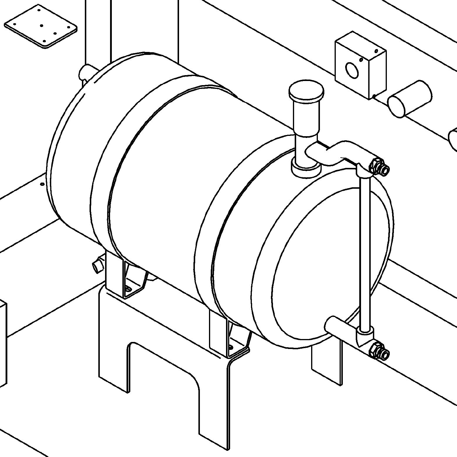
The container can be refilled via the service trap with ordinary windscreen washing fluid.
Volume: see lubricant chart
3.2.10Field
Danger!
Beforeusingtheexcavator,makesurethatthecamerasandtheoutsidemirrorsare correctly adjusted.
Regularly check mirrors and cameras for condition. If necessary: ice to get access to them. Regularly check mirrors and cameras for correct adjustment. For maintenance intervals, refer to the control and maintenance chart. Replace damaged mirrors and cameras immediately.
To cover the correct area: Set the cameras and adjust the outside mirrors so as to be ableto see a person standingoutofthehatchedareadefinedbythefourcheckpointsgivenonthefigure above.
3.2.11Lighting
Regularly check lighting devices for condition. If necessary: ice to get access to them. For maintenance intervals, refer to the control and maintenance chart.
1 Attachment floodlight
2 Attachment floodlight
2_2Attachment floodlight (optional, not represented)
2_3Attachment floodlight (optional, not represented)
6_3
6_4
6_5
Counterweight floodlight (optional, not represented)
Counterweight floodlight (optional, not represented)
Counterweight floodlight (optional, not represented)
The access and the outfit of the cab
3 Top of cabin floodlight
4 Top of cabin floodlight
5 Counterweight floodlight
6 Counterweight floodlight
6_2Counterweight floodlight (optional, not represented)
7 Cab elevation floodlight
7_2Cab elevation floodlight (optional, not represented)
8 Hydraulic tank floodlight
8_2Hydraulic tank floodlight (optional, not represented)
Working light and attachment floodlights
Floodlights 1, 2, 3, 4, 7 and 8 as well as optional floodlights 2_2, 2_3, 7_2 and 8_2 can be activated using button S10 on the control keyboard.
Floodlights 3, 4, 7, 7_2, 8 and 8_2 constitute working light.
Floodlights 1, 2, 2_2 and 2_3 are attachment floodlights.
Press button.
Working light is activated.
LED 1 in the button illuminates.
Press button again.
Working light is deactivated.
LED 1 in the button goes out.
Attachment floodlights are activated. LED 2 in the button illuminates.
Press button again.
Working light and attachment floodlights are switched on. LEDs 1 and 2 in the button illuminate.
Press button again.
Working light and attachment floodlights are switched off. LEDs 1 and 2 in the button go out.
Counterweight floodlights
Floodlights 5 and 6 as wellas optional floodlights 6_2, 6_3, 6_4 and 6_5 can be activated using button S22 on the control keyboard. Press button.
Counterweight floodlights are switched on. LED in button illuminates.
Press button again.
Counterweight floodlights are switched off. LED in the button goes out.
3.2.12Heating/air-conditioning system
A heater and an air conditioner are installed in the cab as standard equipment. The heater is installed on the cab floor. The evaporator for the air conditioning system is integrated in the roof of the cab and the condenser is installed in the air conditioning unit behind the cab.
3-46 Ventilation system
The heater as well as the air conditioner can both be used, at the same time and independently of each other to ventilate the cab.
Ventilation with the heater
Push the lever 1 all the way forward. The water supply is closed.
Push the button S12 to select desired air flow. The fresh air enters into the cab via openings on the steps and via the vents on the left and right front
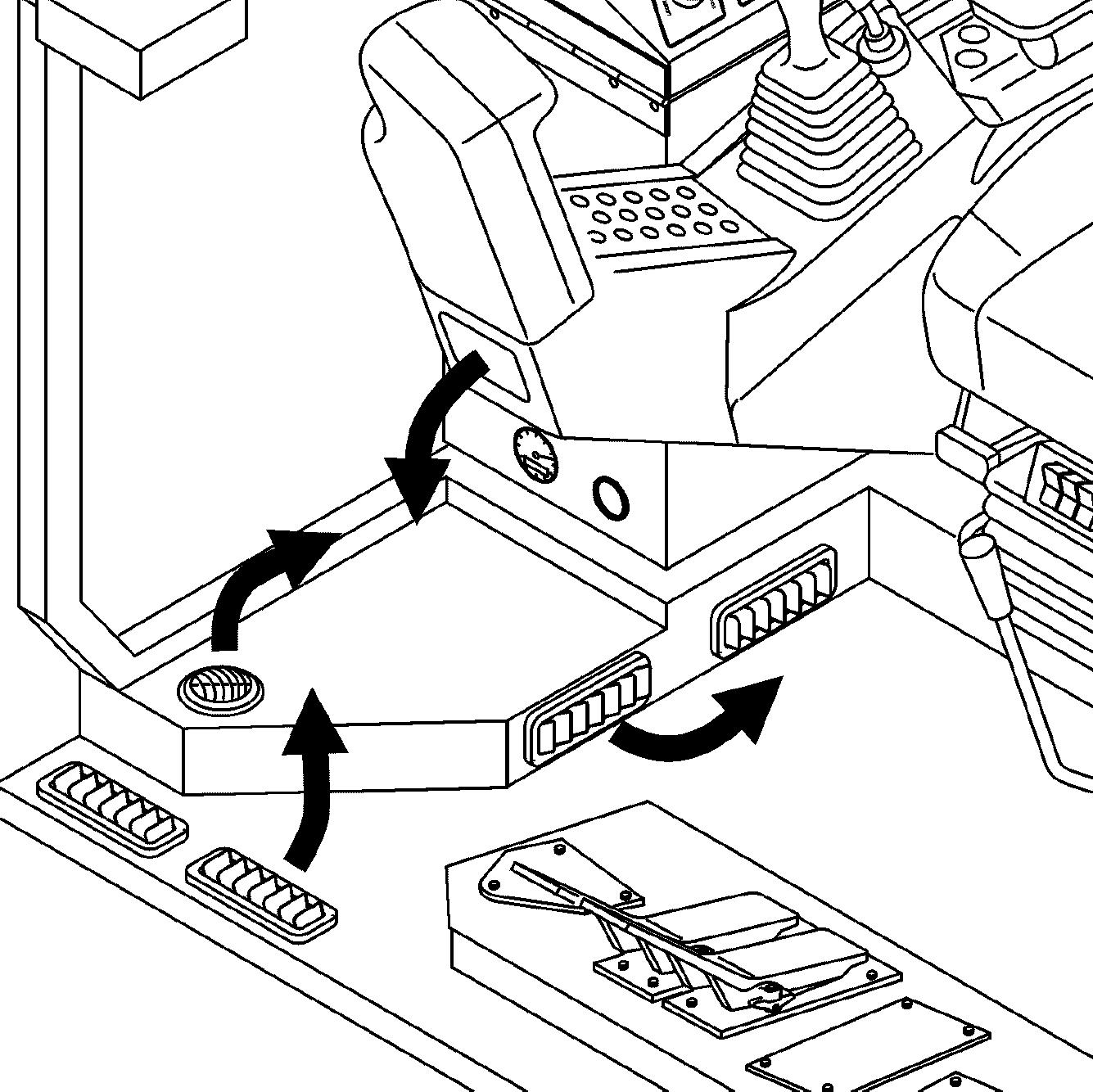
Movethelever2 toregulatetheamountof freshair /recirculatedaircominginto the cab.
If the lever 2 is pushed forward, the fan recirculates the air in the cab.