
HYDRAULIC EXCAVATOR GEN00224-02 PC2000 -11 PC2000 -11E0 SERIAL NUMBERS 30001 and up
Many units are large in size and heavy in weight and may be handled in a dangerous place or posture and many workers may have to work together to sling them with cranes.
FOREWORD
In particular, the above meeting is more important when worker of different languages and customs work together.
The following is a reference supervision system diagram.
Note that this manual does not describe the whole specification of the machine but describes only the basic specification.
Since this machine is large in size, it is divided into some units to meet the transportation conditions and regulations applied to the transportation route when shipped from our factory. This manual describes how to assemble the units into the complete machine in the field. We hope that this machine will display its quality and you will use it safely according to the operation manual.
Work leader Work supervisor Crane director deputyDirectoranddirector Liaison man Operator for assembly Interpreter Mechanics Sharing of work
If you have any question when dividing and transporting the machine by yourself in future, ask one of our distributors.
(Instruction system)
Accordingly, before starting the assembly work, the work supervisor is required to hold a safety meeting to oblige the workers to put on protective gear and appoint a work leader and a crane work signal man and allot roles to all the workers for safe work.
When the work equipment is installed, the engine must be operated. Accordingly, before installing the work equipment, inspect and maintain the machine thoroughly.
CONTENTS A.COATINGTIGHTENINGTOOLSLISTTRANSPORTATIONKITFLOWCHARTASSEMBLYDISPOSALPRECAUTIONSSPECIFICATIONS.............................................................................................................1FORFIELDASSEMBLY.........................................................................2OFREMOVEDPARTS...................................................................................3PROCEDURE,ASSEMBLYEQUIPMENTANDSCHEDULE......................4OFMAINASSEMBLYPROCEDURE........................................................5LAYOUTDIAGRAM....................................................................................................6POSTURES.....................................................................................7OFPARTSSENTINDIVIDUALLY....................16ANDEQUIPMENTTOBEUSEDFORLOCALASSEMBLY....................38TORQUE....................................................................................................40MATERIALSLIST...............45ASSEMBLYOFCHASSIS.... 49 <Assembly of undercarriage> A-1. Assembly of track frame assembly and center frame assembly.... 50 A-2. Installation of idler cushion cylinder piping........................................................... 53 A-3. Installation of travel motor piping.......................................................................... 54 A-4. Installation of travel motor cover............... 55 A-5. Filling swing circle with grease............................................................................. 58 A-6. Assembly of revolving frame assembly and undercarriage........... 59 A-7. Installation of swing machinery (front) assembly (27t) Installation of swing motor (front) assembly (32t)................................................. 61 A-8. Connection of swivel joint piping............... 62 A-9. Connection of swing circle grease piping............................................................. 63 <Assembly of upper structure> A-10. Installation of hydraulic tank assembly....... 64 A-11. Installation of fuel tank assembly.......................................................................... 69 A-12. Connection of fuel tank assembly piping and wiring.................... 70 A-13. Installation of cab base assembly................. 72 A-14. Installation of emergency escape ladder.............................................................. 74 A-15. Installation of left floor assembly.............. 75 A-16. Connection of cab base assembly piping............ 80 A-17. Connection of cab base assembly wiring............................................................. 83 A-18. Connection of left floor assembly heater piping... 90 <Coupling of power module> A-19. Connection of left floor assembly wiring.............. 91 A-20. Installation of tail pipe.............................................................................. 93 A-21. Installation of power module assembly................................................................. 94 A-22. Connection of suction piping 96 A-23. Connection of oil cooler piping and pump drain piping...... 98 A-24. Connection of fan motor drain piping.................................................................... 99 A-25. Installation of suction unit undercover................. 100 A-26. Connection of delivery piping.............. 101 A-27. Connection of pilot piping and fan motor piping 104 A-28. Connection of power module assembly fuel piping ............. 105 A-29. Connection of power module assembly air conditioner piping ............................. 107 A-30. Connection of power module assembly heater piping. 108 A-31. Connection of power module assembly wiring 109 SELECTION OF WIRE ROPES USED FOR ASSEMBLY 47 SELECTION OF NYLON SLINGS USED FOR ASSEMBLY ............................................. 48
<Coupling of operator's cab> A-32. Installation of operator's cab assembly 113 A-33. Installation of rotary lamp (if equipped)................................................................ 117 A-34. Installation of Iridium antenna 119 A-35. Connection of operator's cab assembly wiring 120 A-36. Connection of operator's cab assembly hydraulic piping..................................... 123 A-37. Connection of operator's cab assembly window washer hose 125 A-38. Connection of operator's cab assembly air conditioner piping............................. 126 A-39. Connection of operator's cab assembly heater piping ......................................... 128 A-40. Installation of operator's cab rear floor assembly 129 A-41. Installation of handrail around operator's cab ...................................................... 130 <Coupling of exterior parts, counterweight, etc.> A-42. Installation of track frame ladder 131 A-43. Installation of power module side catwalk assemblies (right and left)................. 132 A-44. Installation of right floor assembly, grease can cover assembly and center floor........................................................ 133 A-45. Installation of fuel tank right catwalk assembly .................................................... 135 A-46. Installation of fuel tank front catwalk assembly 136 A-47. Adjustment of exterior parts clearance................................................................. 137 A-48. Connection of grease reel piping 138 A-49. Installation of access ladder assembly............ 139 A-50. Installation of counterweight assembly ................................................................ 140 A-51. Installation of deformation preventing stoppers for catwalk assemblies (left and right) on the side of power module......................................................... 141 A-52. Installation of handrail on counterweight.............................................................. 142 A-53. Installation of handrail clamps 143 A-54. Connection of fuel cut wire................................................................................... 146 A-55. Connection of drain piping under power module......... 147 A-56. Connection of battery wiring................ 148 <Starting of engine and inspection and servicing procedures> A-57. Setting of hydraulic tank strainer 149 A-58. Starting engine, checking oil and coolant levels, bleeding air from each part, and adjusting track ............................................................................................... 150 A-59. Permanent tightening of swing circle bolt.... 165 A-60. Parts to be touched up after field assembly (chassis side).................................. 166 A-61. Connection of engine heater connection port 167 A-62. Installation of optional harness 170 A-63. Installation of KomVision and rear lamp............................................................... 171 A-64. Connection of emergency stop switch (if equipped) (at the right below power module) 180 A-65. Connection of emergency stop switch (if equipped) (at the left side of ladder) 181 A-66. Installation of engine oil and PTO oil pipings ....................................................... 182 A-67. Installation of coolant piping 183 A-68. Installation of guard bracket (if equipped)............................................................ 184 C.ASSEMBLY OF BACKHOE........................................................................................... 185 <Coupling of boom> C- 1. Installation of boom cylinder................. 186 C- 2. Installation of boom cylinder hoses...................................................................... 188 C- 3. Assembly of boom sub assembly.............. 189 C- 4. Installation of boom assembly.............................................................................. 194 C- 5. Installation of boom cylinder head side................................................................ 196 C- 6. Installation of hoses between boom and chassis ................................................. 198
<Coupling of arm> C- 7. Installation of arm assembly................................................................................. 199 C- 8. Installation of arm cylinder 202 C- 9. Connection of hoses between boom and arm 203 C-10. Connection of auto grease piping......................................................................... 204 C-11. Connection of wiring between boom and chassis 205 <Coupling of bucket> C-12. Installation of bucket assembly ............................................................................ 206 C-13. Installation of bucket link 209 C-14. Bleeding air from cylinders 211 C-15. Parts to be touched up after field assembly (work equipment side)..................... 215 C-16. Bleeding air from auto grease circuit 216 M.INSPECTION AND SERVICING PROCEDURES AFTER ASSEMBLY 219 M-1. Inspection of oil levels and coolant levels and using standard of fuel and lubricant 220 M- 2. Flushing of hydraulic circuit.................................................................................. 222 M- 3. Releasing residual pressure from hydraulic circuit............................................... 231 M-4. Releasing residual pressure from HIC circuit and check of gas pressure in HIC accumulator......................................................................... 232 M- 5. Charging air conditioner with refrigerant 233 M- 6. Installed angles of mirrors 236 M- 7. Installed angles of lights....................................................................................... 239 M-8. Method for starting up KOMTRAX terminal and default setting of KOMTRAX Plus controller...................................................... 242 PC2000-11 Main pump air bleeding check sheet.............................................................. 256 FIELD ASSEMBLY INSPECTION REPORT (BACKHOE) M- 9. Method of camera calibration for KomVision...................................................... 243
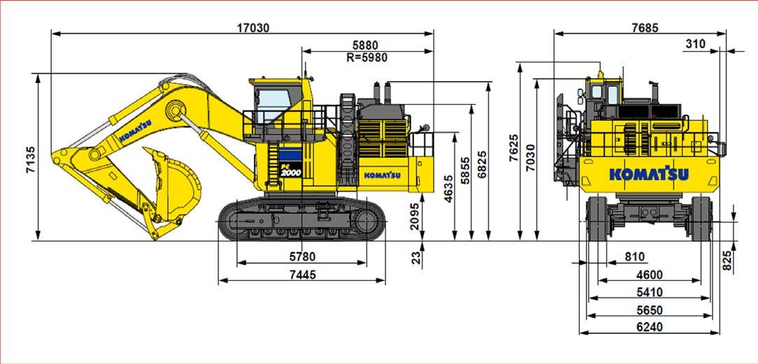
1 SPECIFICATIONS PC2000-11, -11E0 Backhoe Item Unit PC2000-11, -11E0 Operating weight (including 1 operator) kg 201,500 Bucket capacity Backhoe m3 12.0 Name of engine Komatsu SAA12V140E-7 diesel engine Engine horsepower kW{HP}/rpm 794{1,065}/1,800 Min. ground distance 825 Travel speed (Low/High) km/h 2.7 Swing speed rpm 4.8
1.Selection of work place
Is
1)When selecting a work place, consider the following.
Is the work place sufficiently wide for loading and unloading the machine? (See the kit layout drawIsing.)the ground sufficiently hard? (The machine and crane truck must not sink into the ground.) the ground flat? (The ground surface must not be uneven or sloping.) the road to inlet/outlet of the work place sufficient for turning the trailer and crane truck?
Is
3)Avoid working outdoors while strong wind is blowing or it is raining.
1)Are the parking brakes of the trailer and crane truck applied securely and are their wheels locked with chocks during work? Are outriggers, if installed, used securely?
2)Are the temperature and pressure of the engine, hydraulic oil, coolant, etc. lowered sufficiently during 3)Iswork?horn or another signal is made to warn around when the engine is started? In addition, is it checked that work equipment control lever and other control levers are in neutral and the fuel control dial (or fuel control lever) is in the low idle position?
5)Is entry prohibition for outsiders to the work place observed?
1)Aretools.
The work supervisor or the work leader must check the following items constantly and make all the workers observe them.
The work supervisor or the work leader should not do the work while reading this manual but should read and understand this manual thoroughly and then start the work.
5. The work supervisor or the work leader is required to hold a meeting with all the workers at the beginning of every morning and explain the work plan of the day to them and give them instructions to observe the safe work.
2 PRECAUTIONS FOR FIELD ASSEMBLY
all the workers wearing helmets and other protective gear which they are obliged to wear? If special protective gear is necessary, check that it is prepared and can be used without problem.
4. k Check during actual work
2)Are all the slings and tools prepared? Check in advance that they are ready to be used without problem. In particular, check wooden blocks for internal decay and cracking.
2)Take care extremely that dirt or water will not enter the hydraulic circuit while it is assembled.
4)Take measures to protect the machine from sand, dirt and rainwater while the work is stopped.
4)Is the balance of the slung item checked extremely during sling work with the crane?
3.Preparation and check of protective gear, slings and tools
2.How to do work
The work supervisor or the work leader must perform the following checks about protective gear, slings and
In particular, write the "Precautions" for each work process in a sheet to explain or stick that sheet to the work place so that all the workers will observe the precautions.
DISPOSAL OF REMOVED PARTS
The above plugs, jigs, etc. are removed when the machine is assembled and become unnecessary after completion of the machine. Since they are useful when the machine needs to be transported in future, however, we recommend you to keep them as long as possible.
As described in "FOREWORD", when this machine is transported, it is divided into some units such as the body, undercarriage, cab, work equipment, etc. according to the transportation measure, regulations,etc. Accordingly, the hydraulic pipings and hydraulic hoses to connect the units, oil inlets and outlets of the hydraulic devices, and parts which must not be damaged are plugged or covered to prevent oil leakage, entry of dirt and dust, and damage during transportation.
3
In addition, fixing jigs are used to prevent a trouble caused by a fall or a shake during transportation and to facilitate loading, unloading and crane work.
4 ASSEMBLY PROCEDURE, ASSEMBLY EQUIPMENT AND SCHEDULE (Disassembled to 32t)

5 FLOWCHART OF MAIN ASSEMBLY PROCEDURE Work necessary to assembly from 27 ton parts Assembly of undercarriage (Coupling of crawler and center) Coupling of revolving frame Installation of fuel tank Installation of cab base Installation of power module Installation of cab Installation of external covers and steps Installation of InstallationMotoringcounterweightofboomcylinderInstallationofboomInstallationofarmInstallationofbucket Sub-assembly of arm Sub-assembly of boom Sub-assembly of cab base Installation of left floor Installation of (front)machinery Assembly of undercarriage (Coupling of crawler and center)
6 KIT LAYOUT DIAGRAM • The dimensions given below are the minimum dimensions needed. • When selecting a work place, see "Points regarding local assembly". • When installing the revolving frame, place wooden blocks 700 mm high under it. Trailer

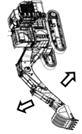
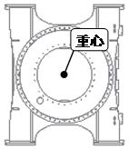
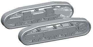
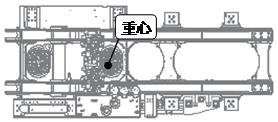
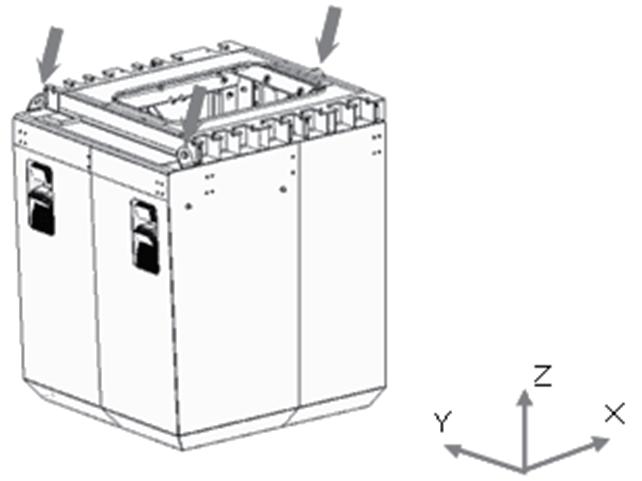
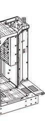
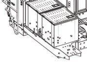
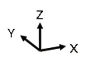
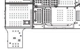
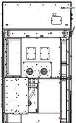
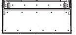
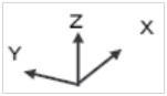
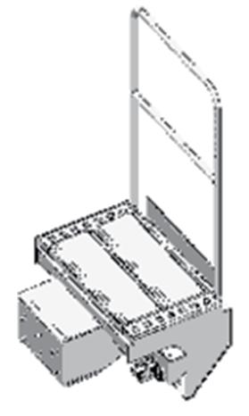
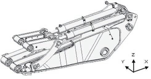
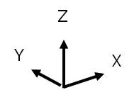
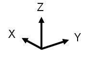
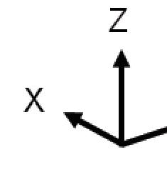
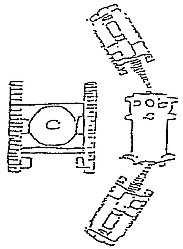
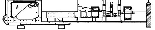
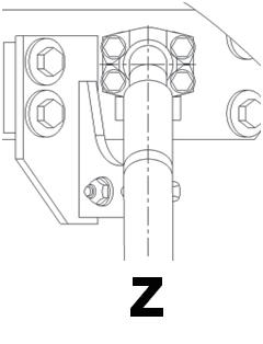
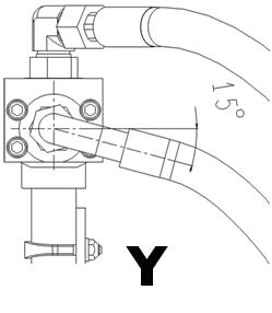
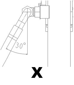
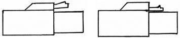
7 TRANSPORTATION POSTURES For transporting of the machine, ask your Komatsu distributor. Each dimension in the following figures is rounded up to the next 5 mm and each weight is rounded up to the next 100 kg. The arrows indicate the hanging points of each assembly. Values in <> of X, Y and Z indicate the packing dimensions. t Transportation posture of each kit (1)Center frame assembly (2)Crawler frame assembly (3)Revolving frame assembly Center of gravity Top view XOverall length (mm)3,815 <3,950> YOverall width (mm)3,190 <3,400> ZOverall height (mm) 2,210 <2,400> WWeight (kg) 18,100 • With swivel and fixing bar • With swing circle and grease piping • With grease bath (Grease is packed separately) • With travel piping tubes • With HIC piping (Accumulator has been pressurized) Undercover[Remarks] is optional. Center of gravity Top view For each XOverallcrawler length (mm)7,435 <7,500> YOverall width (mm)1,720 <1,800> ZOverall height (mm) 1,920 <1,950> WWeight (kg)26,000 • With motor and motor guard Full[Remarks]rollerguard is optional.Center of gravity Top view todisassembledWhen32ton todisassembledWhen27ton XOverall length (mm)7,575 <7,600> YOverall width (mm)3,180 <3,400> ZOverall height (mm)2,9202,640 WWeight (kg)31,50026,500 • With 6 hoses to boom • With 4 oil cooler hoses • With grease tank When disassembled to 27 ton, hydraulic tank assembly and machine (front) assembly are packed separately. (Special sling)


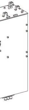
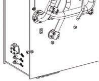
8 (4)Fuel tank assembly (5)Cab base assembly (6)Left floor assembly Center of gravity Top view XOverall length (mm)3,100 <3,350> YOverall width (mm) ,875 <1,150> ZOverall height (mm) 2,070 <2,300> WWeight (kg) 2,140 • With working lamp • With fuel level sensor (without fuel) Top view Center of gravity XOverall length (mm)2,100 <2,300> YOverall width (mm)2,000 <2,300> ZOverall height (mm) 2,700 <3,000> WWeight (kg)2,600 • With head lamp and working lamp • With emergency escape ladder Center of gravity XOverall length (mm)2,510 <3,080> YOverall width (mm)3,280 <4,130> ZOverall height (mm)3,150 <3,230> WWeight (kg) 2,230 • With battery Top view


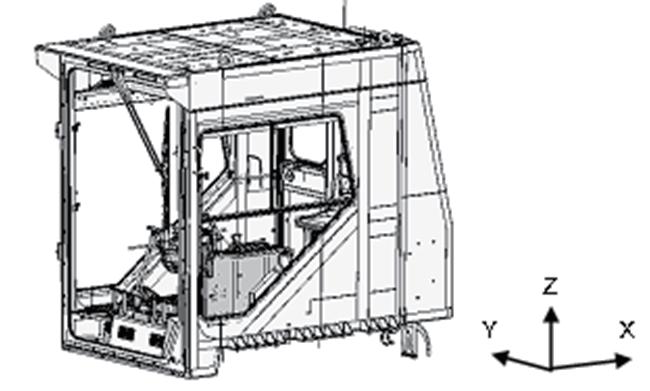
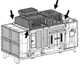
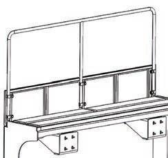
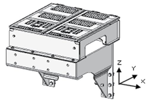
9 (7) Power module assembly (8)Operator's cab assembly (9) Counterweight assembly TopCenterview of gravity XOverall length (mm)5,215 <5,300> YOverall width (mm)2,455 <2,600> ZOverall height (mm)3,320 <3,475> WWeight (kg) 16,800 • With super hood • With handrail on radiator side Top viewCenter of gravity XOverall length (mm)2,855 <3,100> YOverall width (mm)1,880 <2,050> ZOverall height (mm) 2,520 <2,700> WWeight (kg)2,000 • With antenna retracted • With mirrors folded Front[Remarks]guard is optional. Top viewCenter of gravity XOverall length (mm)6,240 <6,300> YOverall width (mm)1,115 <1,250> ZOverall height (mm)1,505 <1,600> WWeight (kg) 24,800 [Parts packed separately] Handrail, bolts


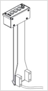
10 (10) Catwalk assembly on power container side (right and left) (11) Grease can cover assembly (12) Switch box assembly Top Centerviewof gravity For each XOverallcatwalk length (mm)2,310 YOverall width (mm) ,545 ZOverall height (mm) Right 2,085, Left 2,410 WWeight (kg) ,330 [Parts packed separately] Stopper, shim, bolts Right Left Top viewCenter of gravity XOverall length (mm)1,030 YOverall width (mm)1,025 ZOverall height (mm) ,995 WWeight (kg) ,260 XOverall length (mm)300 YOverall width (mm)200 ZOverall height (mm)1,000 WWeight (kg) 20


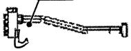
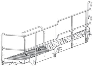
11 (13) Right floor assembly (14) Right catwalk assembly (15) Front catwalk assembly Y Z X Top viewCenter of gravity XOverall length (mm)1,000 YOverall width (mm)1,350 ZOverall height (mm)2,085 WWeight (kg) ,230 Y Z X TopCenterviewof gravity XOverall length (mm)3,560 YOverall width (mm)1,300 ZOverall height (mm)1,865 WWeight (kg) ,390 • With grease reelTop Centerview of gravity XOverall length (mm) ,715 YOverall width (mm) ,810 ZOverall height (mm)1,540 WWeight (kg) , 90


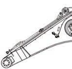
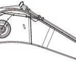
12 (16) Cab rear floor assembly (17) Boom assembly (18) Arm assembly X Z Y Top viewCenter of gravity XOverall length (mm)1,470 YOverall width (mm)1,320 ZOverall height (mm) ,520 WWeight (kg) , 70 X Z Y XOverall length (mm)9,170 <9,200> YOverall width (mm)2,065 <2,100> ZOverall height (mm)3,195 <3,500> WWeight (kg)21,500CenterofgravityLeftsideviewLeftsideviewCenter of gravity XOverall length (mm)5,495 <5,500> YOverall width (mm)1,605 <1,700> ZOverall height (mm) 2,055 <2,100> WWeight (kg) 12,950 • With bucket cylinder


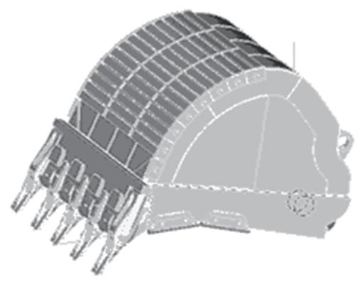
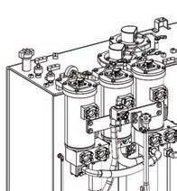
13 (19) Bucket assembly (20) Arm cylinder tube assembly (21) Hydraulic tank assembly Left sideCenterview of gravity XOverall length (mm)3,540 YOverall width (mm)2,790 ZOverall height (mm)2,320 WWeight (kg) 9,700 Specifications of standard bucket for crushedXOverallstones length (mm)1,240 YOverall width (mm) ,320 ZOverall height (mm) ,365 WWeight (kg) , 60 Center of gravity Left side view Top viewCenter of gravity XOverall length (mm)1,860 YOverall width (mm)1,115 ZOverall height (mm)2,085 WWeight (kg) 1,750

14 (22) Swing machinery (front) assembly (23) Cab L.H. catwalk (24) Cab front catwalk TopCenterview of gravity XOverall length (mm) ,775 YOverall width (mm) ,675 ZOverall height (mm)1,335 WWeight (kg) 1,050 TopCenterview of gravity XOverall length (mm)3,660 YOverall width (mm) ,620 ZOverall height (mm)1,355 WWeight (kg) ,260 XOverall length (mm)1,840 YOverall width (mm) ,560 ZOverall height (mm) 11,325 WWeight (kg) ,100 Center of gravity Top view


15 •Method of installing chassis hanging jig
16 LIST OF PARTS SENT INDIVIDUALLY (Assembly of undercarriage) A No. Part No. Part Name Q’ty ProcedureAssemblyNo. Remarks A-1 21T-30-71160 BOLT 76 A-1 A-2 21T-30-71170 WASHER 76 A-1 A-3 208-30-11850 -SG COVER 1 A-1 A-4 208-30-11861 GASKET 1 A-1 A-5 01024-81225 BOLT 3 A-1 A-6 07000-B3025 O-RING 2 A-2 A-7 01010-81660 BOLT 4 A-2 A-8 01643-31645 WASHER 4 A-2 A-9 07000-B3048 O-RING 4 A-3 A-10 11Y-62-11980 O-RING 2 A-3 A-11 21T-30-32173-XC COVER 1 A-4 A-12 21T-30-32183-XC COVER 1 A-4 A-13 01010-82460 BOLT 10 A-4 A-14 17A-54-44130 WASHER 10 A-4 A-15 01010-82460 BOLT 16 A-4 A-16 01643-32460 WASHER 16 A-4 A-17 21T-30-32370 COLLAR 16 A-4 A-18 21T-30-48120-XC COVER 5 A-4 Only Under Cover Specification of Center XCFramePaint Color Black Gray A-19 01024-82465 BOLT 20 A-4 Only Under Cover Specification of Center Frame A-20 21U-46-31270 WASHER 20 A-4 Only Under Cover Specification of Center Frame
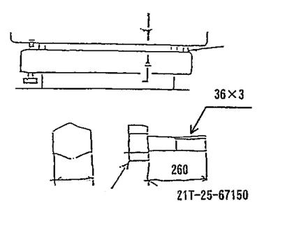
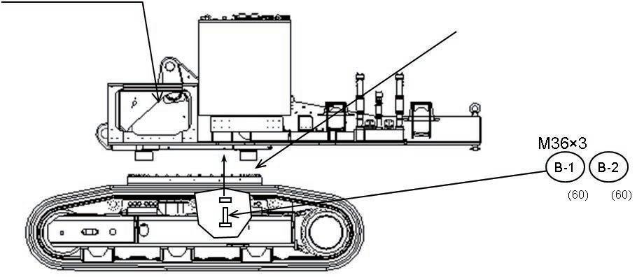
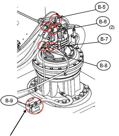
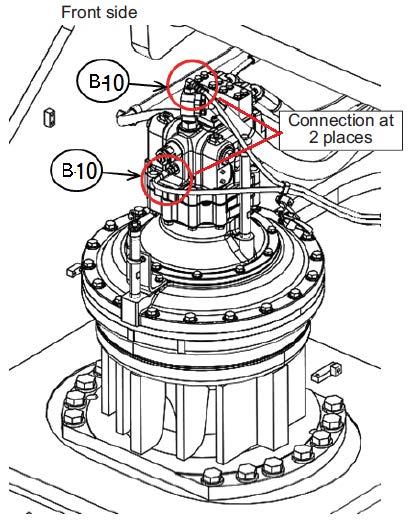
17 LIST OF PARTS SENT INDIVIDUALLY (Coupling of revolving frame) B No. Part No. Part Name Q’ty ProcedureAssemblyNo. Remarks B-1 21T-25-67150 BOLT 60 A-6 B-2 01643-33690 WASHER 60 A-6 B-3 01010-83090 BOLT 14 A-7 B-4 01643-33080 WASHER 14 A-7 B-5 07000-B3038 O-RING 1 A-7 B-6 07000-B3032 O-RING 2 A-7 B-7 02896-61015 O-RING 1 A-7 B-8 02896-61009 O-RING 1 A-7 B-9 01024-81225 BOLT 1 A-7 B-10 02896-61008 O-RING 2 A-7 B-11 11Y-62-11980 O-RING 1 A-8 B-12 07000-B3048 O-RING 4 A-8 B-13 07000-B5230 O-RING 2 A-10 B-14 01011-83010 BOLT 12 A-10 B-15 21T-26-11460 WASHER 12 A-10 B-16 07000-B2060 O-RING 8 A-10 B-17 11Y-62-11980 O-RING 3 A-10 B-18 07000-B3032 O-RING 1 A-10
18 LIST OF PARTS SENT INDIVIDUALLY (Assembly of upper structure) C No. Part No. Part Name Q’ty ProcedureAssemblyNo. Remarks C-1 01011-83010 BOLT 20 A-11 C-2 21T-26-11460 WASHER 20 A-11 C-3 04435-52212 CLIP 1 A-12 C-4 02896-61012 O-RING 1 A-12 C-5 02896-61015 O-RING 2 A-12 C-6 02896-61018 O-RING 2 A-12 C-7 01024-81220 BOLT 1 A-12 C-8 09460-00000 LOCK 1 A-12 C-9 04434-52312 CLIP 1 A-12 C 10 04434-51912 CLIP 2 A-12 C-11 01024-81220 BOLT 3 A-12 C 12 01024-81250 BOLT 1 A-12 C 13 04434-52112 CLIP 1 A-12 C 14 01034-81245 BOLT 10 A 13 C 15 01010-81680 BOLT 10 A-13 C 16 2A5-01-11590 WASHER 10 A-13 C 17 21T-54-31140-XC CLAMP 1 A-13 C 18 21T-54-31150-XC CLAMP 1 A-13 C 19 01034-81245 BOLT 2 A-13 C 20 20Y-06-43230 WORK LAMP A. 2 A-13 C 21 21T-06-32820 WORK LAMP A. 1 A-13 C 22 04434-51012 CLIP 12 A-13 C 23 01024-81220 BOLT 12 A-13 C 24 01011-82035 BOLT 20 A-13 C 25 01011-82045 BOLT 7 A-13 C 26 567-40-41380 WASHER 27 A-13
19 No. Part No. Part Name Q’ty ProcedureAssemblyNo. Remarks C 27 01034-81225 BOLT 8 A-14 C 28 01034-81235 BOLT 2 A-14 C 29 01024-81225 BOLT 8 A-14 C 30 21T-54-37661-XC BRACKET 1 A 14 C 31 21T-54-37621-XC BRACKET 1 A-14 C 32 21T-54-37690-XC LADDER 1 A-14 C 33 21T-54-37681 LADDER 1 A-14 C 34 21T-53-33141-XC HANDRAIL 2 A-14 C 35 21T-54-43370-NK COVER 1 A-15 C 36 01034-81240 BOLT 4 A-15 C 37 21T-53-32820-NK BRACKET 2 A-15 C 38 01034-81240 BOLT 4 A-15 C 39 01010-82075 BOLT 9 A-15 C 40 15R-70-16370 WASHER 9 A-15 C 41 01011-82470 BOLT 1 A-15 C-42 21T-54-43820 WASHER 1 A-15 C 43 01010-82470 BOLT 11 A-15 C 44 21T-54-43810 WASHER 17 A-15 C 45 01010-82480 BOLT 6 A-15 C 46 21T-54-44570 PLATE 1 A-15 C 47 21T-54-44550 SPACER 3 A-15 C 48 21T-54-44560 PLATE 1 A-15 C 49 01010-81655 BOLT 3 A-15 C 50 01643-31645 WASHER 3 A-15 C 51 21T-53-32271-SA SHIM 6 A-15 C 52 21T-53-32350-SA SHIM 10 A-15 C 53 21T-54-41241 SHIM 3 A-15 C 54 21T 54-43570-XC COVER 1 A-15 C 55 01034-81230 BOLT,SEMS 3 A-15 C 56 21T-53-32280-SA PLATE 6 A-15 C 57 02896-61012 O-RING 6 A-16 C 58 02896-61009 O-RING 7 A-16 C 59 02896-61018 O-RING 2 A-16 C 60 02896-61012 O-RING 1 A-16
20 No. Part No. Part Name Q’ty ProcedureAssemblyNo. Remarks C 61 04435-52112 CLIP 2 A-16 C 62 01024-81225 BOLT A-16 C 63 154-979-1480 COLLAR 1 A-16 C 64 01024-81275 BOLT 1 A-16 C 65 01024-81025 BOLT 2 A-16 C 66 01024-81020 BOLT 1 A-17 C 67 04434-52312 CLIP 1 A-17 C 68 01024-81225 BOLT 1 A-17 C 69 04434-52712 CLIP 2 A-17 C 70 01024-81225 BOLT 2 A-17 C 71 20Y-06-43230 WORK LAMP A. 1 A-17 C 72 01024-81285 BOLT 4 A-17 C 73 04434-51012 CLIP 1 A-17 C 74 04434-51412 CLIP 3 A-17 C 75 04434-51712 CLIP 2 A-17 C 76 04434-51912 CLIP 2 A-17 C-77 01024-81225 BOLT 7 A-17 C 78 04434-52312 CLIP 1 A-17 C 79 175-40-22540 SPACER 1 A-17 C 80 01024-81275 BOLT 1 A-17 C 81 07281 00419 CLAMP 2 A-18 C 82 01024-81025 BOLT 1 A-19 C 83 01024-81220 BOLT 1 A-19 C 84 04434-51012 CLIP 1 A-19 C 85 01024-81225 BOLT 12 A-64 C 86 01024-81235 BOLT 4 A-64 C 87 01024-81230 BOLT 8 A-64 C 88 01024-81225 BOLT 2 A-64
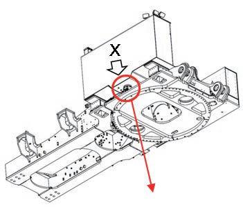
21 No. Part No. Part Name Q’ty ProcedureAssemblyNo. Remarks C 89 04434-51712 CLIP 13 C 90 01024-81225 BOLT 13 C 91 21T-06-44212 HARNESS 1 C 92 21T-06-32980 HARNESS 1 C 93 04434-51412 CLIP 3 C 94 04434-51012 CLIP 3 C 95 01024-81250 BOLT 1 C 96 01024-81230 BOLT 2 C 97 198-911-6170-NK BRACKET 2 C 98 04434-51712 HARNESS 2 C 99 01024-81225 BOLT 2 C 100 04435-51012 CLIP 4 C 101 04434-51412 CLIP 4 C 102 01024-81225 BOLT 4 C 103 205-03-71331 COLLAR 1 C 104 04434-51012 CLIP 1 C 105 04434-51412 CLIP 1 C 106 01024-81270 BOLT 1 C 107 04435-51012 CLIP 3 C 108 04434-51412 CLIP 3 C 109 01024-81225 BOLT 3 C 110 04435-51012 CLIP 13 C 111 04434-51412 CLIP 13 C 112 01024-81225 BOLT 13 C 113 21T-06-41690-NK COVER 2 C 114 21T-06-41671-NK COVER 1 C 115 01024-81225 BOLT 6 C 116 21T-06-33360 BRACKET 1 C 117 01024-81225 BOLT 2 C 118 08193-21012 CLIP 1 C 119 20Y-06-43230 WORK LAMP ASS`Y 2 C 120 04434-51012 CLIP 11 C 121 01024-81225 BOLT 11 C 122 21T-06-41690-NK COVER 2 A-63A-63A-63A-63A-63A-63A-63A-63A-63A-63A-63A-63A-63A-63A-63A-63A-63A-63A-63A-63A-63A-63A-63A-63A-63A-63A-63A-63A-63A-63A-63A-63A-63A-63
22 No. Part No. Part Name Q’ty ProcedureAssemblyNo. Remarks C 123 21T-06-41671-NK COVER 1 C 124 01024-81225 BOLT 6 C 125 21T-06-33360 BRACKET 1 C 126 01024-81225 BOLT 2 C 127 08193-21012 CLIP 1 C 128 20Y-06-43230 WORK LAMP ASS`Y 1 A-63A-63A-63A-63A-63A-63
23 LIST OF PARTS SENT INDIVIDUALLY (Coupling of power module) D No. Part No. Part Name Q’ty ProcedureAssemblyNo. Remarks D-1 21M-01-18130 TAIL PIPE 2 A-20 D-2 01010-D1240 BOLT 12 A-20 D-3 17A-54-42370 WASHER 12 A-20 D-4 6162-14-5640 RAIN CAP 2 A-20 D-5 21T-01-41950-XC COVER 2 A-20 D-6 21T-54-31121-NK PLATE 4 A-21 D-7 21T-54-31130 BOLT 20 A-21 D-8 01643-34212 WASHER 20 A-21 D-9 07000-B2140 O-RING 2 A-22 D-10 07000-B2100 O-RING 1 A-22 D-11 209-62-41341 CLAMP 4 A-22 D-12 20Y-62-51671 CLAMP 2 A-22 D-13 07000-B2060 O-RING 4 A-23 D-14 07279-02011 HOSE 1 A-23 D-15 07000-B3048 O-RING 4 A-23 D-16 07000-B3032 O-RING 1 A-24 D-17 21T-54-34931-NK FRAME 1 A-25 D-18 21T-54-42590-NK COVER 1 A-25 D-19 21T-54-34991-NK COVER 1 A-25 D-20 21T-54-42580-NK COVER 1 A-25 D-21 21T-54-42520-NK COVER 1 A-25 D-22 21T-54-34961-NK COVER 1 A-25 D-23 21T-54-42530-NK COVER 1 A-25 D-24 203-54-62670 COLLAR 2 A-25 D-25 01024-81225 BOLT 2 A-25 D-26 01034-81225 BOLT 26 A-25 D-27 21T-54-34920-NK COVER 1 A-25 D-28 01024-81225 BOLT 2 A-25 D-29 01024-81235 BOLT 3 A-25 D-30 07000-B3048 O-RING 4 A-26 D-31 02896-61012 O-RING 1 A-26
24 No. Part No. Part Name Q’ty ProcedureAssemblyNo. Remarks D-32 07000-B3025 O-RING 2 A-27 D-33 07000-B3032 O-RING 1 A-27 D-34 02896-61018 O-RING 2 A-28 D-35 02896-61015 O-RING 1 A-28 D-36 02896-61015 O-RING 1 A-28 D-37 08038-10035 CAP 4 A-31 D-38 08038-04030 CAP 4 A-31 D-39 08028-55065 WIRE 2 A-31 D-40 01024-81020 BOLT 2 A-31 D-41 01024-81020 BOLT 4 A-31
25 LIST OF PARTS SENT INDIVIDUALLY (operator's cab) E E No. Part No. Part Name Q’ty ProcedureAssemblyNo. Remarks E-1 21T-54-34151-XC COVER 1 A-32 E-2 01034-81225 BOLT 6 A-32 E-3 21T-54-37980 BRACKET 6 A-32 E-4 21T-54-36680 PLATE 9 A-32 E-5 21T-54-36690 PLATE 12 A-32 E-6 01024-81030 BOLT 12 A-32 E-7 21T-54-37990 CUSHION 6 A-32 E-8 21T-54-35312 -NK BRACKET 8 A-32 E-9 8230-46-1130 BOLT 16 A-32 E-10 01643-32060 WASHER 16 A-32 E-11 21T-54-36661 PLATE 16 A-32 E-12 21T-54-36671 PLATE 8 A-32 E-13 21T-54-35321 CUSHION 8 A-32 E-14 21T-54-35732 PIN 4 A-32 E-15 04020-00514 COTTER PIN 8 A-32 E-16 01050-52040 BOLT 4 A-32 E-17 01643-32060 WASHER 4 A-32 E-18 8295-06-1480 LAMP 1 A-33 E-19 21T-06-17430-XC BRACKET 1 A-33 E-20 01024-81225 BOLT 2 A-33 E-21 8295-06-1480 LAMP 1 A-33 E-22 21T-06-33610-XC PLATE 1 A-33 E-23 21T-06 17430-XC BRACKET 1 A-33 E-24 01024-81225 BOLT 2 A-33 E-25 04434-51012 CLIP 1 A-33 E-26 01024-81220 BOLT 1 A-33 E-27 01024-81020 BOLT 1 A-35 E-28 207-62-62770-NK BRACKET 1 A-35 E-29 01024-81225 BOLT 2 A-35 E-30 04434-53212 CLIP 1 A-35 E-31 01024-81225 BOLT 2 A-35
26 No. Part No. Part Name Q’ty ProcedureAssemblyNo. Remarks E-32 04434-51712 CLIP 2 A-35 E-33 01024-81225 BOLT 1 A-35 E-34 04434-53212 CLIP 1 A-35 E-35 08034-20519 BAND 2 A-35 E-37 02896-61012 O-RING 10 A-36 E-38 02896-61009 O-RING 2 A-36 E-39 21T-979-4421 SEAL 4 A-38 E-40 21N-979-8160 OIL COMPRESSOR 1 A-29, A-38 E-41 21N-62-52670-NK BRACKET 1 A 38 E-42 01024-81225 BOLT 4 A-38 E-43 04434-51612 CLIP 1 A-38 E-44 04434-51412 CLIP 1 A-38 E-45 21T-979-4620-XC BRACKET 1 A-38 E-46 01024-81230 BOLT 2 A-38 E-47 22U-03-31760 CLIP 1 A-38 E-48 04434-52212 CLIP 1 A-38 E-49 07281-00259 CLAMP 4 A-39 E-50 01024-81225 BOLT 14 A-40 E-51 21T-54-41761-XC HANDRAIL 1 A-41 E-52 01024-81240 BOLT,SEMS 12 A-41 E-53 198-54-79161-XC BRACKET 1 A-41 E-54 01034-81225 BOLT 4 A-41 E-55 20Y 979-3310 DRUM 10 M 5
27 LIST OF PARTS SENT INDIVIDUALLY (Coupling of counterweight etc) F No. Part No. Part Name Q’ty ProcedureAssemblyNo. Remarks F-1 21T-30-32231 XC BRACKET 2 A-42 F-2 21T-30-32241-XC LADDER 2 A-42 F-3 01010-82460 BOLT 8 A-42 F-4 01010-82450 BOLT 8 A-42 F-5 01643-32460 WASHER 16 A-42 F-6 01010-81240 BOLT 16 A-43 F-7 21T-53-32290-SA SHIM 12 A-43 F-8 01010-82080 BOLT 12 A-44 F-9 01010-82060 BOLT 8 A-44 F 10 01643-32060 WASHER 20 A-44 F-11 21T-53-31550-NK PLATE 1 A-44 F 12 21T-54-31560-NK PLATE 1 A-44 F 13 21T-54-33331-NK STEP 1 A-44 F 14 01034-81250 BOLT 4 A-44 F 15 21T-54-33731-NK COVER 1 A-44 F 16 21T-54-33781-NK COVER 1 A-44 F 17 21T-54-33791-NK COVER 1 A-44 F 18 21T-53-31590-NK COVER 1 A-44 F 19 01034-81230 BOLT 16 A-44 F 20 01034-81285 BOLT 4 A-44 F 21 01034-81240 BOLT 16 A-45 F 22 01034-81250 BOLT 6 A-46 F 23 21T-54-41620-XC STEP 1 A-49 F 24 01034-81230 BOLT 4 A-49 F 25 01034-81230 BOLT 6 A-49
28 No. Part No. Part Name Q’ty ProcedureAssemblyNo. Remarks F 27 21T-46-34120 BOLT 12 A-50 4 of 12 bolts are used for installation of transportation jig. F 28 209-46-11210 WASHER 12 A-50 4 of 12 bolts are used for installation of transportation jig. F 29 21T-46-34141-NK COVER 2 A-50 F 30 21T-46-34131-NK 2 A-50 F 31 01024-81225 BOLT 12 A 50 F 32 21T-53-33640-NK BRACKET 2 A-51 F 33 21T-53-33650-NK SHIM 4 A-51 F 34 01024-81255 BOLT 4 A-51 F 35 21T-54-42570-XC HANDRAIL 1 A-52 F 36 21T-54-42560-XC HANDRAIL 1 A-52 F 37 01034-81250 BOLT 16 A-52 F 38 21T-54-32911-XC CLAMP 10 A-53 F 39 21T-54-32921-XC CLAMP 10 A-53 F 40 01010-81250 BOLT 20 A-53 F 41 175-54-34170 WASHER 20 A-53 F 42 21T-54-31140-XC CLAMP 1 A-53 F 43 21T-54-31150-XC CLAMP 1 A-53 F 44 01034-81245 BOLT 2 A-53 F 45 21T-54-37220 CHAIN 1 A-54 F 46 04530-10815 BOLT 1 A-54 F 47 21T-04-32180 WIRE ROPE 1 A-54 F 48 07281-00419 CLAMP 2 A-55 F 49 07281-00259 CLAMP 1 A-55 COVER
29 No. Part No. Part Name Q’ty ProcedureAssemblyNo. Remarks F 50 01024-81230 BOLT,SEMS 4 A-61 F 51 01024-81016 BOLT,SEMS 2 A-61 F 52 04434-51012 CLIP 1 A-61 F 53 04434-51912 CLIP 1 A-61 F 54 01024-81230 BOLT,SEMS 1 A-61 F 55 04434-51012 CLIP 1 A-61 F 56 04434-51912 CLIP 1 A-61 F 57 195-33-11220 SPACER 1 A-61 F 58 01024-81230 BOLT,SEMS 1 A-61 F 59 21T-06-31570-NK BRACKET 1 A-61 F 60 01024-81230 BOLT,SEMS 4 A-61 F 61 04434-53412 CLIP 2 A-61 F 62 01024-81245 BOLT,SEMS 1 A-61 F 63 04434-51912 CLIP 1 A-61 F 64 01024-81230 BOLT,SEMS 1 A-61 F 65 02896-61012 O-RING 1 A-61 F 66 07281-00419 CLAMP 2 A-61 F-67 01024-81250 BOLT,SEMS 1 A-62 F 68 04434-51712 CLIP 1 A-62 F 69 195-33-11220 SPACER 1 A-62 F 70 01024-81220 BOLT 2 A-64 F 71 04434-51012 CLIP 2 A-64 F 72 21T-06-31141 ROPE(RED) 1 A-64 F 73 21T-06-31170 SHACKLE 1 A-64 F 74 21T-06-41130 ROPE(RED) 1 A-65 F 75 21T-06-31170 SHACKLE 1 A-65 F 76 281-01 13180 CLIP 3 A-66 F 77 01024-81225 BOLT 3 A-66 F 78 07281-00419 CLAMP 1 A-66 F 79 07281-00259 CLAMP 1 A-66
30 No. Part No. Part Name Q’ty ProcedureAssemblyNo. Remarks F 80 07281-00419 CLAMP 1 A-68 F 81 21T-46-31161-NK BRACKET 1 A-69 F 82 01010-82050 BOLT 4 A-69 F 83 01643-32060 WASHER 4 A-69
31 LIST OF PARTS SENT INDIVIDUALLY (Coupling of boom) H No. Part No. Part Name Q’ty ProcedureAssemblyNo. Remarks H-1 707-01-X5760 XC CYLINDER(L.H)BOOM 1 C-1 H-2 707-01-X5770-XC CYLINDER(R.H)BOOM 1 C-1 H-3 21T-70-31421 SHIM 2 C-1 H-4 21T-70 31470 SHIM 8 C-1 H-5 21T-70-31690 SHIM 8 C-1 H-6 07000-15180 O-RING 4 C-1 H-7 07000-B2060 O-RING 4 C-2 H-8 07000-B3048 O-RING 4 C-2 H-9 21T-64-41860 HOSE 2 C-2 H-10 21T-64-41850 HOSE 2 C-2 H-11 21T-64 39140-NK TUBE 1 C-3 H-12 21T-64-39150-NK TUBE 1 C-3 H-13 21T-64-39160-NK TUBE 1 C-3 H-14 07000 B3048 O-RING 2 C-3 H-15 07000-B2060 O-RING 7 C-3 H-16 01643-31845 WAHSER 12 C-3 H-17 01010-81865 BOLT 12 C-3 H-19 707-01-X5780-NK ARM CYLINDER(L.H) 1 C-3 H-20 707-01-X5790-NK ARM CYLINDER(R.H) 1 C-3 H-21 07000-12140 O-RING 4 C-3 H-22 21T-70-31441-SA SHIM 4 C-3 H-23 07084-02022 HOSE 2 C-3 H-24 07085-01418 HOSE 1 C-3 H-25 07085-01420 HOSE 1 C-3 H-26 07000-B2060 O-RING 4 C-3 H-27 07000-B3048 O-RING 4 C-3 H-28 07371-51470 FLANGE 4 C-3 H-29 07371-52080 FLANGE 4 C-3 H-30 01643-31445 WASHER 8 C-3
32 No. Part No. Part Name Q’ty ProcedureAssemblyNo. Remarks H-31 01643-31845 WASHER 8 C-3 H-32 01010-81455 BOLT 8 C-3 H-33 01010 81865 BOLT 8 C-3 H-34 20Y-06-43230 WORK LAMP A. 4 C-3 H-35 20Y-06-21551 BRACKET 4 C-3 H-36 01643-31445 WASHER 4 C-3 H-37 01010-81430 BOLT 4 C-3 H-38 01024-81225 BOLT 4 C-3 H-39 209-72-11311 SEAL 4 C-3 H-40 21T-70-31290 SEAL 2 C-3 H-41 08193-21012 CLIP 4 C-3 H-42 21T-70-31490 SHIM 16 C-4 H-43 21T-70-31480 SHIM 8 C-4 H-44 07000-B3048 O-RING 4 C-2 H-45 07371-51470 FLANGE 8 C-2 H-46 01010-81455 BOLT 16 C-2 H-47 01643-31445 WASHER 16 C-2 H-48 21T-64-32980 ADAPTER 4 C-2 H-49 21T-64-32990 BOLT 16 C-2 H-50 07000-15180 O-RING 4 C-5
33 LIST OF PARTS SENT INDIVIDUALLY (Coupling of arm) I No. Part No. Part Name Q’ty ProcedureAssemblyNo. Remarks I-1 07000-B2060 O-RING 6 C-6 I-2 21T-70-31290 SEAL 2 C-7 I-3 21N-70-12160 SEAL 4 C-7 I-4 209-72-11261 SEAL 4 C-7 I-5 21T-70-31391 SHIM 2 C-7 I-6 21T-70-31780 SHIM 1 C-7 I-7 21T-70-31810 SHIM 1 C-7 I-8 21T-70-31820 SHIM 1 C-7 I-9 07000-15260 O-RING 2 C-7 I-10 21T-70-32181-SA SHIM 4 C-8 I-11 07000-12140 O-RING 4 C-8 I-12 07371-51470 FLANGE 4 C-9 I-13 07371-52080 FLANGE 4 C-9 I-14 07084-41427 HOSE 2 C-9 I-15 21T-64-41870 HOSE 2 C-9 I-16 07000-B3048 O-RING 4 C-9 I-17 07000-B2060 O-RING 4 C-9 -18 01643-31445 WASHER 8 C-9 I-19 01643-31845 WASHER 8 C-9 I-20 01010-81455 BOLT 8 C-9 I-21 01010-81865 BOLT 8 C-9 I-22 21T-68-31830-NK TUBE 1 C-10 I-23 203-973-5660-NK CLAMP 3 C-10 I-24 203-973-5720-NK SEAT 3 C-10 I-25 21T-04-31620-NK PLATE 3 C-10 I-26 01024 81055 BOLT 6 C-10 I-27 21T-70-32330-NK BRACKET 1 C-10 I-28 01024-81225 BOLT 2 C-10 I-29 07631-20409 HOSE 1 C-10
34 No. Part No. Part Name Q’ty ProcedureAssemblyNo. Remarks I-30 04434-51712 CLIP 2 C-11 I-31 01024-81220 BOLT 2 C-11
35 LIST OF PARTS SENT INDIVIDUALLY (Coupling of Bucket) J No. Part No. Part Name Q’ty ProcedureAssemblyNo. Remarks J-1 209-72-11261 SEAL 4 C-12 J-2 209-70-71370 O-RING 4 C-12 J-3 205-09-61240 BOLT 4 C-12 J-4 01640-20610 WASHER 8 C-12 J-5 01596-00606 NUT 4 C-12 J-6 8247-62-1810 SWIVEL 2 C-12 J-7 07000-12011 O-RING 2 C-12 J-8 21T-70-34333-NK COVER 2 C-12 J-9 07000-15195 O-RING 2 C-12 J-10 01010-83695 BOLT 12 C-12 J-11 01643-33690 WASHER 12 C-12 J-12 21T-70-33171 PIN 2 C-12 J-13 21T-70-34341-NK COVER 2 C-12 J-14 07000-15175 O-RING 2 C-12 J-15 01010-83685 BOLT 12 C-12 J-16 01643-33690 WASHER 12 C-12 J-18 21T-70-33250-NK PIN 2 C-13 J-19 21T-72-73170-NK STOPPER 2 C-13 J-20 01010-81645 BOLT 6 C-13 J-21 01643-31645 WASHER 6 C-13 J-22 21N-72-11230 SHIM 2 C-13
36 LIST OF PARTS SENT INDIVIDUALLY (Bleeding air from cylinder and hydraulic circuit) K No. Part No. Part Name Q’ty ProcedureAssemblyNo. Remarks K-1 21N-60-51220 COVER 3 M-2 K-2 569-33-72140 JOINT 3 M-2 K-3 566-32-11620 CAP 3 M-2 K-4 566-32-11430 BLEEDER 3 M-2 K-5 07000-B5180 O-RING 3 M-2 K-6 07002-61223 O-RING 3 M-2 K-7 07069-34057 SPRING 3 M 2 K-8 22U-60-21380 PLATE 3 M-2 K-9 209-60-77551 ELEMENT 3 M-2 K-11 21T-60-41410 ELEMENT 3 M-2 K-12 20Y-60-31140 STRAINER 3 M-2 K-13 - COVER A. 3 M-2 K-15 21M-60-51250 SUPPORT 1 M-6 K-16 21T-53-31791-XC BRACKET 1 M-6 K-17 21T-53-33860-XC BRACKET 1 M-6 K-18 21T-53-31841-XC BRACKET 1 M-6 K-19 21T-53-31850-XC BRACKET 1 M-6 K-20 07283-53444 SEAT 10 M-6 K-21 07283-33450 CLIP 10 M-6 K-22 01597 01009 NUT 24 M-6 K-23 01643-31032 WASHER 24 M-6 K-24 07283-33442 CLIP 2 M-6 K-25 20Y-54-61630-XC CLAMP 1 M-6 K-26 01252-71025 BOLT 2 M-6 K-27 01010-81640 BOLT 2 M-6 K-28 21T-72-12620 WASHER 1 M-6 K-29 01643-31645 WASHER 1 M-6 K-30 23S-54-36270 MIRROR 1 M-6 K-31 56B-54-17313 MIRROR A. 1 M-6 Parts already installed to machine Parts already installed to machine Parts already installed to machine K-14 01024-81235 BOLT 3 M-2 Parts already installed to machine
37 No. Part No. Part Name Q’ty ProcedureAssemblyNo. Remarks K-32 23S-54-36270 MIRROR 2 M-6 K-33 21T-54-34690-XC SUPPORT 1 M-6 K-34 21T-54-79620-XC CLAMP 2 M-6 K-35 01252-71025 BOLT 4 M-6 K-36 21T-54-34850-XC PLATE 1 M-6 K-37 21T-54-34680-XC PLATE 1 M-6 K-38 07283-32236 CLIP 4 M-6 K-39 01643-31032 WASHER 8 M-6 K-40 01597-01009 NUT 8 M-6 K-41 2A5-54-13421 MIRROR 1 M-6 K-42 2A5-54-16550-XC SPRING PIN 1 M-6 K-43 20Y-54-61630-XC CLAMP 1 M-6 K-44 01252-A1030 BOLT 2 M-6 K-45 21T-06-32810 WORK LAMP ASS`Y 1 M-7 K-46 22B-06-11690 3 M-7WORK LAMP ASS`Y
38 TOOLS AND EQUIPMENT TO BE USED FOR LOCAL ASSEMBLY No. Part name Specification Q'ty Remarks Equipment 1Engine air compressor0.7 MPa, 15 m3/min 1With 200 V, 100 V generator 2Crane truck 70 ton / 45 ton 2 / 1 3Grease pump Pneumatic 1For greasing work equipment 4Mobile elevating work platform10 m 12 workers 5Lift work stand 10 step, 3,000 mm 1 Substituted by mobile elevating work platform 6 Stepladder 5 step, 1,500 mm 2 7 3 step, 900 mm 2 8Hydraulic wrench 750 kgm 1Track frame, power container 9Hydraulic pump For hydraulic wrench, 200 V 1Track frame, power container Tool Air impact wrench Tightening capacity (Nm) Note 1)Q'ty Socket installed dimension (mm) Note 2) 10 Up to 196 Nm {Up to 20 kgm} 1 12.7 mm 11 Up to 588 Nm {Up to 60 kgm} 1 19.0 mm 12 Up to 981 Nm {Up to 100 kgm}1 25.4 mm 13 Up to 2,940 Nm {Up to 300 kgm}1 38.1 mm or spline type Note 3)14 Up to 6,374 Nm {Up to 650 kgm}1 Torque wrench Tightening capacity (Nm) Note 1)Q'ty Socket installed dimension (mm) Note 2) 15 58.6 Nm {6 kgm} 1 12.7 mm 16 137 Nm {14 kgm} 1 12.7 mm 17 206 Nm {21 kgm} 1 19.0 mm 18 412 Nm {42 kgm} 1 19.0 mm Socket for air impact wrench, socket for torque wrench Width across flats dimensionsQ'ty Socket installed dimension (mm) Note 2) 19 17, 19, 22 1 each 12.7 mm 24, 27, 30 1 each 19.0 mm 32, 36 1 each 25.4 mm 41, 46, 50, 55, 65, 70 1 each 38.1 mm 20 Extension For impact wrench, 300 mm long2 21 For impact wrench, 200 mm long1 22Impact wrench air hoseInside ø 12, Inside ø 19 50 m each 23Air coupler For hoses of size 4, 6 2 sets 2416 time wrench 450 kgm 1 Unnecessary, if hydraulic wrench is available 25 Spanner Width across flats: 30 mm 2 26 Width across flats: 32 mm 2 27 Width across flats: 36 mm 2 28 Width across flats: 41 mm 2 29Standard tool set Sockets, spanners, ring wrenches 2 sets each 30Large hammer (Plastic)10 P 1 31Bar 1 m 2 32 Hydraulic jack 50 ton 2 For receiving center frame to install track frame 33 20 ton 1 For tightening track frame clamping bolt 34Oil receiving pan Large and small 2 each For connecting travel piping and work equipment piping 35Drum can oil filler 1 36Wooden block 300 × 400 8 For supporting revolving frame and center frame46for fuel tank 65 for counterweight 70 for track frame a Match socket installed dimension to impact wrench.
39 Note 1)Prepare an impact wrench on the basis of the tightening capacity. Note 2)The socket installed dimensions are shown for reference. Match the wrench to the socket prepared separately. Note 3)Hydraulic wrench No. 8 in the previous page may be used for bolts of M27 mm or larger. In this case, splined sockets must be prepared (1 piece each of sizes 41, 46, 50, 55, 65, and 70 in width across flats). Tool 37 Tap M10 × P1.5 1 38 M12 × P1.75 1 39 M14 × P2 1 40 M16 × P2 1 41 M20 × P2.5 1 42 M24 × P3 1 43 M27 × P3 1 44 M30 × P3 1 45 M33 × P3 1 46 M36 × P3 1 47 M39 × P3 1 48 M42 × P3 1 49 M45 × P3 1 50 Wire rope sling ø 10 × 3,000 mm 4Catwalk 51 ø 20 × 5,000 mm 4Boom, arm and bucket 52 ø 30 × 6,000 mm 4 Center frame and power container 53 ø 40 × 5,000 mm 4 Counterweight, revolving frame and track frame 54Chain For 15 ton 2Track frame 55 Shackle 5.4 ton 4 Center frame, boom, arm and power container 56 10 ton 4 Track frame and revolving frame 57 20 ton 2Counterweight 58 2 ton 4Fuel tank 59 0.9 ton 4Cabin 60 SB10 2Travel piping cover 61 Synthetic fiber sling 50 mm wide × 3,000 mm 2Boom cylinder 62 25 mm wide × 3,000 mm 2Handrail 63 Lever block 1.5 ton 3Left floor assembly 64 3.0 ton 2 65 6 ton 2 66 Eyebolt M20 × 2.5 2 67 M16 × 2 4 68 M12 × 1.75 4 69 M30 × 3 2 70Pin Pin, ø 50 × 700 mm 2Track frame greaseoil,Fuel, sub-materialsand 71Cleaning liquid Brake cleaner spray can 10 72Hydraulic oil EO10 2400 L 73Diesel fuel 2000 L 74Grease G2-LI (20 L can) 5In grease bath 75 Repair paint Natural yellow spray can 10 76 Black gray spray can 10 77LG-6 TB1215 1 Connecting faces of revolving frame and swing circle 78Air conditioner refrigerantHFC134a (R134a) 2000 g Prepare it only in EU district (EU specification) 79Cloth 1 bundle 20 kgFor cleaning No. Part name Specification Q'ty Remarks 80 Sheet Part PartPartNo.No.No. 562-98-3A120 Sheet , Grid Front 121 For KomVision camera calibration562-98-3A130 Sheet , Grid Side 562-98-3A140 Sheet , Grid Rear Handle Part No. 21T-98-11130 1 For track frame81
40 TIGHTENING TORQUE 1.Tightening torque for bolts Tightening torque for bolts is indicated in the text as shown below. Tighten each bolt to the specified Iftorque.tightening torque for a bolt is not specified in the text, tighten it according to Table 1. 1.TheRemarksthread diameter is the nominal diameter. For example, 16 mm is expressed as M16 and 20 mm is expressed as M20. The pitch in Table 1 is the distance that the bolt advances every turn in the axial direction (Unit: mm). 2. The bolt length is dimension (c) in Fig. 1. 3.The applicable socket size is expressed as 24 mm, 30 mm, etc. Since 24 mm, 30 mm, etc. correspond to dimension (b) in Fig. 1, an applicable socket can be selected from Table 1, too. 4.Tightening torque is expressed as QQQ www or QQQ ± RR. If the target tightening torque is set, expression of QQQ ± RR is applied. Part No. of bolt TTTTT TTTTT Part No. of washer EEEEE EEEEE Bolt specification Thread diameter × Bolt length Tool (Socket) Applicable socket size Tightening torque Nm {QQQ kgm} a: Bolt thread diameter (Nominal diameter) b: Width across flats of bolt head c: Bolt length d: Threaded part of bolt Fig. 1 Thread size (Diameter, pitch, length)
41 a For symbols “a” and “b” in the table, see Fig. 1. Table 1 Tightening torque for bolts not specified in text Unit: Nm {kgm} Nominal size of thread × pitch a (mm) Width across flats (= Socket size) b (mm) Tightening torque Unit : Nm 8.8 – 14.7 {0.9 – 1.5}{1.2}126 × 1 14.7 – 34 {1.5 – 3.5}{2.5}25 34 – 74 {3.5 – 7.5}{5.5}54 54 – 123 {5.5 – 12.5}{9}89 84 – 196 {8.5 – 20}{14}137 147 – 309 {15 – 31.5}{23.5}230 201 – 427 {20.5 – 43.5}{32}315 319 – 608 {32.5 – 62}{47}460 471 – 829 {48 – 84.5}{66.5}650 588 – 1030 {60 – 105}{82.5}810 883 – 1470 {90 – 150}{120}1180 1130 – 1910 {115 – 195}{155}1520 1470 – 2450 {150 – 250}{200}1960 1860 – 3040 {190 – 310}{250}2450 2260 – 3630 {230 – 370}{300}2940 8 × 1.25 10 × 1.5 12 × 1.75 14 × 2 16 × 2 18 × 2.5 20 × 2.5 22 × 2.5 24 × 3 27 × 3 30 × 3 33 × 3 36 × 3 39 × 3 605550464136323027242219171310 Unit : {kgm}
42 2.Tightening torque for pipe threads Proper tightening torque for pipe threads depends on combination of the materials of the male screw and female screw. In this manual, however, select tightening torque from Table 2 and Table 3 on the basis of the material of the male screw. If tightening torque is specified specially in explanation, however, apply that tightening torque. 2.1 If the male screw is made of mild steel or cast iron, apply Table 2. Table 2 Unit: Nm {kgm} 2.2 If the male screw is made of refined steel (heat-treated hard steel), apply Table 3. Table 3 Unit: Nm {kgm} Material of female thread Nominal size SteelCast ironLight alloy 1/8 3.9 6.9 {0.4 0.7} 2.9 5.9 {0.3 0.6} 2.0 3.9 {0.2 0.4} 1/4 5.9 11.8 {0.6 1.2} 4.9 9.8 {0.5 1.0} 3.9 7.8 {0.4 0.8} 3/8 16.7 26.5 {1.7 2.7} 13.7 21.6 {1.4 2.2} 9.8 16.7 {1.0 1.7} 1/2 32.3 52.9 {3.3 5.4} 26.5 43.1 {2.7 4.4} 19.6 32.3 {2.0 3.3} 3/4 51.0 85.3 {5.2 8.7} 42.1 70.6 {4.3 7.2} 31.4 52.9 {3.2 5.4} 1 86.2 173.5 {8.8 17.7} 72.5 146.0 {7.4 14.9} 54.9 111.7 {5.6 11.4} Material of female thread Nominal size Steel Cast ironLight alloy 1/8 16.7 29.4 {1.7 3.0} 9.8 19.6 {1.0 2.0} 6.9 14.7 {0.7 1.5} 1/4 19.6 44.1 {2.0 4.5} 16.7 37.2 {1.7 3.8} 12.7 28.4 {1.3 2.9} 3/8 44.1 93.1 {4.5 9.5} 37.2 77.4 {3.8 7.9} 27.4 58.8 {2.8 6.0} 1/2 98.0 188.2 {10.0 19.2} 83.3 157.8 {8.5 16.1} 60.8 115.6 {6.2 11.8} 3/4 170.5 316.5 {17.4 32.3} 141.1 247.0 {14.4 25.2} 105.8 186.2 {10.8 19.0} 1 367.5 612.5 {37.5 62.5} 309.7 514.5 {31.6 52.5} 235.2 392.0 {24.0 40.0} (in)(in)
43 3.Tightening torque for hydraulic hose connecting nut For the connecting nuts installed to the hydraulic hose adapters in relatively low pressure systems, apply tightening torque in Table 4.1 and 4.2. Table 4.1 Hydraulic hose of face seal type Unit: Nm {kgm} Table 4.2 Hydraulic hose of taper seal type Unit: Nm {kgm} Note: When connecting hose, take care not to twist them. Outside diameter of(mm)hose Width across flats (mm) Tightening torque (Nm {kgm}) Range Target Approx. 6 19 34 54 {3.5 5.5} 44 {4.5} Approx. 10 22 54 93 {5.5 9.5} 74 {7.5} Approx. 13 27 84 132 {8.5 13.5} 103 {10.5} Approx. 16 32 128 186 {13.0 19.0} 157 {16.0} Approx. 20 36 177 245 {18.0 25.0} 216 {22.0} Outside diameter of(mm)hose Width across flats (mm) Tightening torque (Nm {kgm}) Range Target Approx. 6 19 34 - 63 {3.5 6.5} 44 {4.5} Approx. 10 24 59 - 98 {6.0 10.0} 78 {8.0} Approx. 13 27 84 - 132 {8.5 13.5} 103 {10.5} Approx. 16 32 128 - 186 {13.0 19.0} 157 {16.0} Approx. 20 36 177 - 245 {18.0 25.0} 216 {22.0} Type that uses O-ring at this positionTypethat does not use O-ring at this position
44 4.Proper socket sizes for bolts of M39 and larger (Reference) For the proper sizes of sockets or spanners (= width across flats) for tightening hexagon bolts of M39 and larger, see Table 5. Table 5 Unit: mm Thread diameterProper sizes of sockets or spanners M42 65 M45 70 M48 75 M52 80 M56 85 M60 90 M64 95
45 COATING MATERIALS LIST a The coating materials such as adhesives, gasket sealants, and greases used for disassembly and assembly are listed below. a For coating materials not listed below, use the equivalent of products shown in this list. CategoryKomatsu codePart No.Q'tyContainerMain features and applications Adhesive LT-1A790-129-9030150 gTube •Used to prevent rubber gaskets, rubber cushions, and cock plugs from coming out. LT-1B790-129-9050 20 g (2 pcs.) Polyethylenecontainer •Used for plastic (except polyethylene, polypropylene, tetrafluoroethylene and vinyl chloride), rubber, metal, and non-metal parts which require immediate and strong adhesion. LT-209940-0003050 g Polyethylenecontainer •Features: Resistance to heat and •Usedchemicalstofix and seal bolts and plugs. LT-3 (Set790-129-9060ofadhesiveandhardener) Hardener:Adhesive:1kg500g Can •Used to stick metal, glass, and plastics. LT-4790-129-9040250 g Polyethylenecontainer •Used to seal plugs. MHHoltz705 790-126-912075 gTube •Heat-resistant seal used to repair engines Threebond1735 790-129-914050 g Polyethylenecontainer •Quick-setting adhesive •Setting time: Within 5 sec. to 3 min. •Used mainly to stick metals, rubbers, plastics, and woods. Aron-alpha201 790-129-91302 g Polyethylenecontainer •Quick-setting adhesive •Quick-setting type (max. strength is obtained after 30 minutes) •Used mainly to stick rubbers, plastics, and metals. 648-50Loctite 79A-129-911050 cc Polyethylenecontainer •Features: Resistance to heat and •Usedchemicalsforfitted portions used at high temperatures. sealantGasket LG-1790-129-9010200 gTube •Used to stick or seal gaskets and packings of power train case, etc. LG-5790-129-90801 kg Polyethylenecontainer •Used to seal various threaded portions, pipe joints, and flanges. •Used to seal tapered plugs, elbows, and nipples of hydraulic piping. LG-6790-129-9020200 gTube •Features: Silicon-based heat and cold-resistant sealant •Used to sea flange surfaces and threaded portions. •Used to seal oil pan, final drive case, etc. LG-7790-129-90701 kgTube •Features: Silicon-based quick-setting •Usedsealanttoseal flywheel housing, intake manifold, oil pan, thermostat housing, etc. Three1211bond 790-129-9090100 gTube •Gasket sealant used to repair engine Three1207Bbond 419-15-18131100 gTube •Features: Silicon-based, heat and cold-resistant, •Usedimpact-resistantvibration-resistant,sealanttosealtransfercase,etc. Molybdenumdisulfidelubricant LM-G09940-0005160 gCan •Used to lubricate sliding portions (to prevent squeaking). LM-P09940-00040200 gTube •Used to prevent scuffing and seizure of press-fitted portions, shrink-fitted portions, and threaded portions. •Used to lubricate linkages, bearings, etc.
46 CategoryKomatsu codePart No.Q'tyContainerMain applications, features Grease G2-LI SYGA-160CNLISYG2-160LISYG2-400LI-ASYG2-350LISYG2-400LI VariousVarious •General purpose type G2-CA SYGA-160CNCASYG2-160CASYG2-400CA-ASYG2-350CASYG2-400CA VariousVarious •Used for bearings used at normal temperature under light load in contact with water or steam. LM-GlubricantdisulfideMolybdenum(G2-M) SYGA-16CNMSYG2-400M-ASYG2-400M 400 g × 10 400 g × 20 16 kg Bellows-typecontainerCan •Used for parts under heavy load. Hyper *:ForG0-TGreaseWhiteG2-T(*)colddistrict SYG0-400T-ASYG2-16CNTSYG2-400T-A (*) SYG0-16CNT (*) Bellows-typecontainerCan •Seizure resistance and heat resistance higher than molybdenum di•Notsulfideconspicuous on machine since color is white. Biogrease G2-B, G2-BT (*) *:For use at loadandtemperaturehighunderhigh SYGA-16CNBTSYG0-400BTSYGA-16CNBSYG2-400B(*)(*) Bellows-typecontainerCan •Since this grease is decomposed by natural bacteria in short period, it has less effects on microorganisms, animals, and plants. Primer 580PAINTSUNSTARPRIMERSUPER 417-926-3910 20 ml containerGlass glasscabforAdhesive •Used as primer for cab side (Using limit: 4 months after date of manufacture) 580GLASSSUNSTARPRIMERSUPER 20 ml containerGlass •Used as primer for glass side (Using limit: 4 months after date of manufacture) 435-95PAINTSUNSTARPRIMER 22M-54-2723020 ml containerGlass •Used as primer for painted surface on cab side (Using limit: 4 months after date of manufacture) 435-41GLASSSUNSTARPRIMER 22M-54-27240150 mlCan •Used as primer for black ceramic-coated surface on glass side and for hard polycarbonate-coated surface (Using limit: 4 months after date of manufacture) GP-402SASHSUNSTARPRIMER 22M-54-2725020 ml containerGlass •Used as primer for sash (Using(Almite)limit: 4 months after date of manufacture) Adhesive SUPERSEALPENGUINESUNSTAR580"S" or "W" 417-926-3910320 ml Polyethylenecontainer •"S" is used for high-temperature season (April - October) and "W" for low-temperature season (November - April) as adhesive for glass. (Using limit: 4 months after date of manufacture) Sika SikaflexJapan,256HV 20Y-54-39850310 ml Polyethylenecontainer •Used as adhesive for glass. (Using limit: 6 months after date of manufacture) SUPERPENGUINESUNSTAR560 22M-54-27210320 ml container)(SpecialEcocart •Used as adhesive for glass. (Using limit: 6 months after date of manufacture) Caulkingmaterial SEALPENGUINESUNSTARNo.2505 417-926-3920320 ml Polyethylenecontainer •Used to seal joints of glass (Usingparts. limit: 4 months after date of manufacture) SEALANTSILICONESEKISUI 20Y-54-55130333 ml Polyethylenecontainer •Used to seal front window. (Using limit: 6 months after date of manufacture) GE TOSSEALSILICONESTOSHIBA381 22M-54-27220333 mlCartridge •Used to seal joint of glasses. Translucent white seal. (Using limit: 12 months after date of manufacture) 400 g 16 16400kggkg
47 ASSEMBLYFORUSEDPESROWIREOFSELECTION table.followingthetoaccordingassemblyforusedbetoropeswireSelect slings.ropetype24×6ofloadsUsing1Table2,Annex {tf}kNUnit: ropeswireofNumber1pc.2pcs. angleSling 0°= Z <90°90° Z 120° lineverticaltoAngle 0°= Z <45°45° Z 60° coefficientMode M 4111. ropewireofClassification 24G24G24G24A24A24AOuterdiameterof2(ropewire) d (mm) 8 9 10 11.2 (12) 12.5 14 16 18 20 22.4 (24) 25 28 30 31.5 33.5 35.5 37.5 40 42.5 {0.49}4.8Max. {0.63}6.1Max. {0.77}7.6Max. {0.97}9.5Max. {1.1}10Max. {1.2}11Max. {1.5}14Max. {1.9}19Max. {2.5}24Max. {3.1}30Max. {3.9}38Max. {4.4}43Max. {4.8}47Max. {6.1}59Max. {7.0}68Max. {7.7}75Max. {8.7}85Max. {9.8}96Max. {10.9}107Max. {12.4}122Max. {14.0}137Max. {0.53}5.2Max. {0.67}6.6Max. {0.83}8.2Max. {1.0}10Max. {1.2}11Max. {1.3}12Max. {1.6}16Max. {2.1}21Max. {2.7}26Max. {3.3}32Max. {4.2}41Max. {5.2}51Max. {6.5}64Max. {7.5}73Max. {8.3}81Max. {9.4}92Max. {10.5}103Max. {11.7}115Max. {13.4}131Max. {15.1}148Max. {0.68}6.7Max. {0.88}8.5Max. {1.0}10Max. {1.3}13Max. {1.5}14Max. {1.6}15Max. {2.1}19Max. {2.6}26Max. {3.5}33Max. {4.3}42Max. {5.4}53Max. {6.1}60Max. {6.7}65Max. {8.5}82Max. {9.8}95Max. {10.7}105Max. {12.1}119Max. {13.7}134Max. {15.2}149Max. {17.3}170Max. {19.6}191Max. {0.74}7.2Max. {0.93}9.2Max. {1.1}11Max. {1.4}14Max. {1.6}15Max. {1.8}16Max. {2.2}22Max. {2.9}29Max. {3.7}36Max. {4.6}44Max. {5.8}57Max. — {7.2}71Max. {9.1}89Max. {10.5}102Max. {11.6}113Max. {13.1}128Max. {14.7}144Max. {16.3}161Max. {18.7}183Max. {21.1}207Max. {0.49}4.8Max. {0.63}6.1Max. {0.77}7.6Max. {0.97}9.5Max. {1.1}10Max. {1.2}11Max. {1.5}14Max. {1.9}19Max. {2.5}24Max. {3.1}30Max. {3.9}38Max. {4.4}43Max. {4.8}47Max. {6.1}59Max. {7.0}68Max. {7.7}75Max. {8.7}85Max. {9.8}96Max. {10.9}107Max. {12.4}122Max. {14.0}137Max. {0.53}5.2Max. {0.67}6.6Max. {0.83}8.2Max. {1.1}10Max. {1.2}11Max. {1.3}12Max. {1.6}16Max. {2.1}21Max. {2.7}26Max. {3.3}32Max. {4.2}41Max. {5.2}51Max. {6.5}64Max. {7.5}73Max. {8.3}81Max. {9.4}92Max. {10.5}103Max. {11.7}115Max. {13.4}131Max. {15.1}148Max.18 8817-1991B
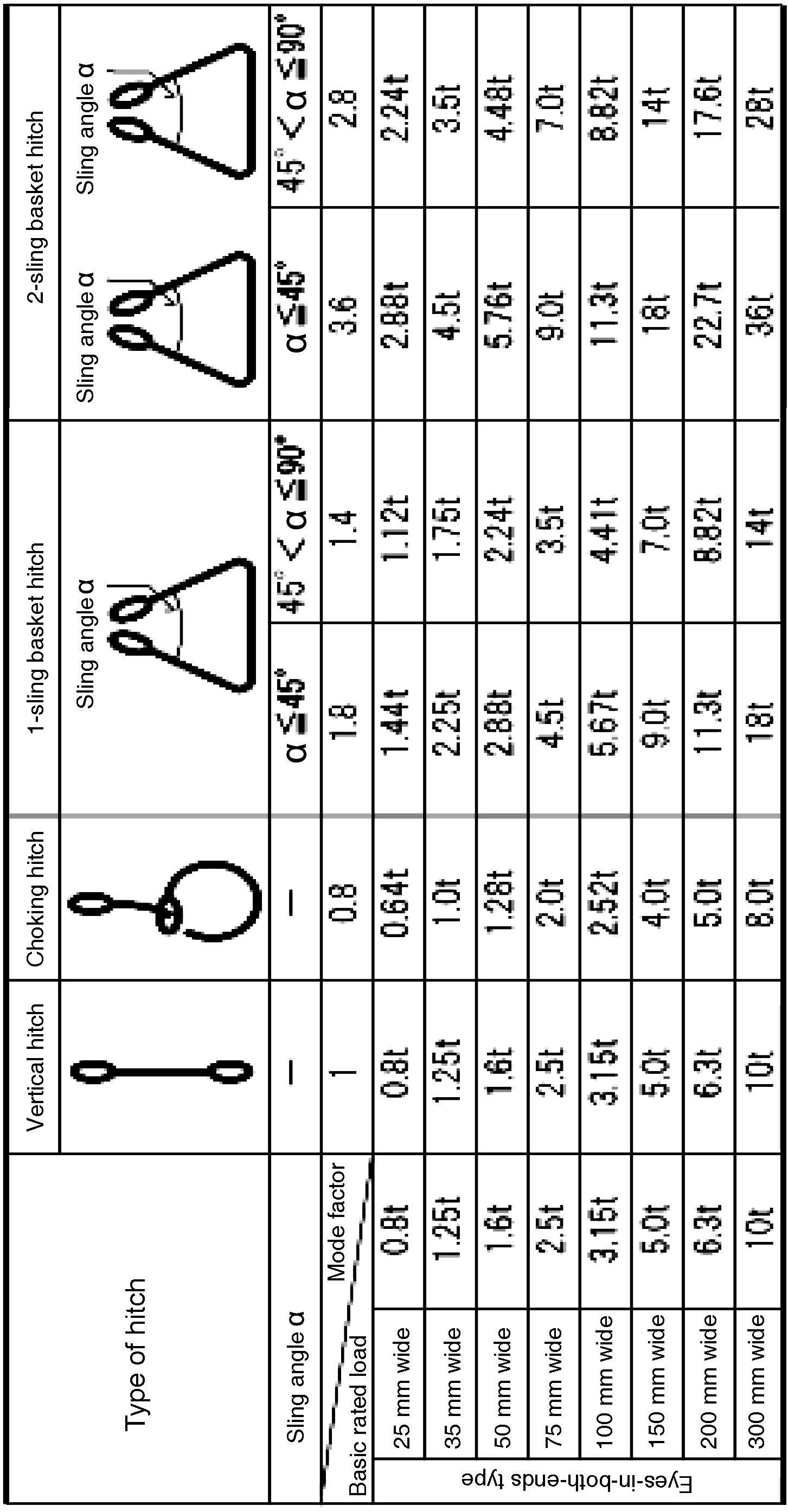
ASSEMBLYFORUSEDSLINGSNYLONOFSELECTION tablefollowingthetoaccordingassemblyforusedwiresSelect t type)(WW-1DtableloadRated 48
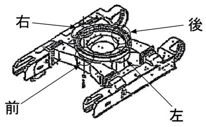
49 A.ASSEMBLY OF CHASSIS 1.InRemarksthe "drawings" in this manual, parts and places are indicated by 1, 2, 3 ---, but indicated by (1), (2), (3) --- in the tables and texts. 2.InExample:some places of this manual, the words of front, rear, right hand and left hand of machine are used. Those words indicate the directions seen from the operator's seat with the sprocket at the rear as shown below, unless otherwise specified. (6)Washer(5)Bolt(4)Bolt(3)Washer(2)Collar(1)Plate Front Left hand Right hand Operator's seatRear SprocketRear Front Left handRight hand Operator’s seat Sprocket
50 Assembly procedure Assembly of track frame assembly and center frame assembly (1/3)A-1 Precautions Tools required Equipment required a When slinging the center frame, take care not to crush the grease piping of the circuit with wires. • Check the coupling bolts and retap them. • Put on safety glasses, and clean the threaded holes by blowing air into them. • Finger-tighten the coupling bolts until they are seated. Name Q’ty Name Q’ty Power wrench (21T-98-11120)(×16) 1Hydraulic jack 50t 2 Socket 38 × 70 mm (21T-98-11190) 1Truck crane 70 t 2 (21T-98-11130)Handle 1Center frame stand 2 Socket 70 mm 1 Tap (M45 × 3) 1PreventOthers seizure Retap all coupling bolt holes to M45 x P3, and be sure to finger-tighten the coupling bolts until they are seated. Width across flats 4413 – 4903 Nm (450 – 500 kgm) Tightening torque Center frame assembly Track frame assembly (left) Track frame assembly (right) Apply wooden blocks etc. to parts which wire ropes will touch. No.Part No.Parts A-501024-81225Bolt3A-4208-30-11861Gasket1A-3208-30-11850-SGCover1A-221T-30-71170Washer76A-121T-30-71160Bolt76nameQ'ty Air impact wrench 1


Left RightCenter frame assembly Rear view Use only stands before coupling. After coupling with left track frame, left stand is not necessary any more. above figure)
Assembly procedure Assembly of track frame assembly and center frame assembly (2/3)A-1
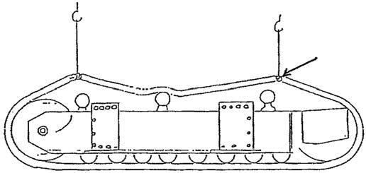
Method of slinging track frame If 2 cranes are used, holes can be aligned easily.
ø50 × 700 mm (Hard steel) 2Crane 70t 2 Wire ø40 × 5 (Generalpurpose)m 2 Others
[Before
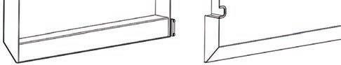
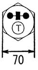
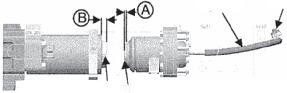
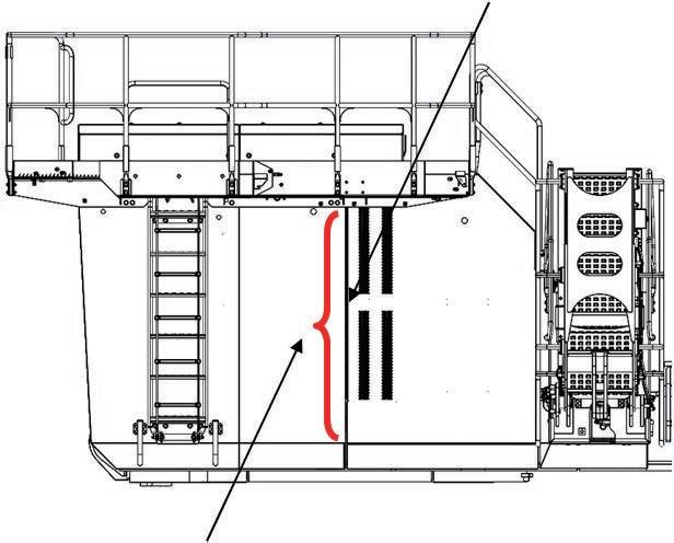
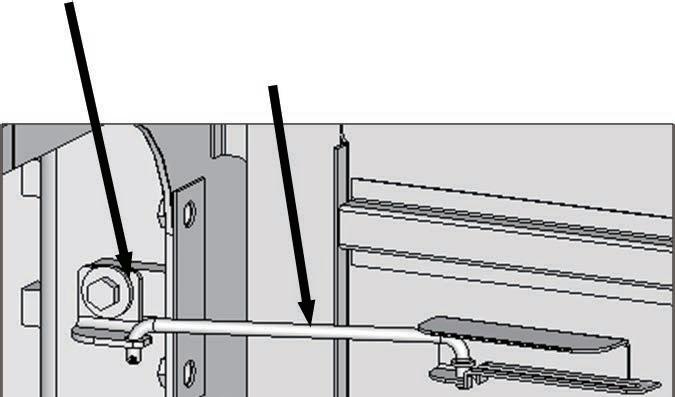
• Confirm that projecting length (A) of the plunger on hydraulic idler cushion side is approx. 10 mm. If the projection is not approx. 10 mm, remove the oil stopper of the hose and discharge hydraulic oil inside the cylinder. Thereafter, install the oil stopper of the hose again.
• Confirm that projecting length (B) of the plunger on grease side (when being filled with grease) is approx. 35 mm. If the projection is not approx. 35 mm, make necessary adjustments by charging or discharging grease through the grease fitting.
51 1)Place the left track frame assembly as shown in the figure at 2)Slingright.the center frame assembly with a 70-ton crane and couple it with the track frames. 3)Remove the plugs from the coupling surface and clean the coupling surface in advance. 4)Insert all the bolts, tighten them temporarily, and support only the right side of the center frame on a jack. 5)Sling the right track frame assembly with the 70-ton crane and couple it with the center frame. At this time, the jack under the center frame should be heightened a little for the ease of coupling. a If you pull in the right track toward the center frame with a chain block, you can work easily. 6)Insert all the bolts, tighten them temporarily, and lower the 7)Removecrane.the jack.
70 t 70 t
Tools required Equipment required Name Q’t Name Q’t
20 GripPipe 45 t 45 t Pin (See
Oil stopperHose Plunger on hydraulic idler cushion side Plunger on grease side Pin Precautions sling by crane]
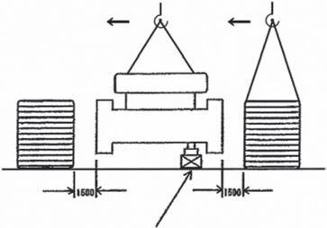

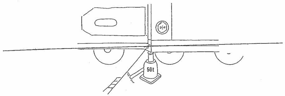
52 1)Eliminate the clearance between the mating faces of the track frame and center frame (at the top, bottom, right and left). Jack up the track frame, if necessary. 2)Coupling bolt Power wrench (×16) + 36 kgm torque wrench Mounting bolt size: M45 × P3 Tightening torque: 450 – 500 kgm Assembly procedure Assembly of track frame assembly and center frame assembly (3/3)A-1 Precautions Tools required Equipment required When installing the clamping bolts, remove the piping at the rear of the center frame (so that you can use an impact wrench easily). (See Assembly procedure A-3.) Name Q’ty Name Q’ty 20t Jack 2 Others 20Input:t 35 kgm If input exceeds 35 kgm, power wrench may be broken. <Tightening order>
53 Assembly procedure Installation of idler cushion cylinder pipingA-2 Precautions Tools required Equipment required 1)When connecting the crawler frame, remove the bolts and bracket marked with ※ 2)Be careful not to damage tubes during connecting work. 3)Be sure to connect L.H. and R.H. sides of cylinder piping. Name Q’ty Name Q’ty 17 mm Socket 1 24 mm Socket 1 Air impact wrench 1 Others R.H. side L.H. side This figure shows R.H. side. No.Part No.Parts A-607000-B3025O-ring2nameQ'ty A-7 01010-81660Bolt4 A-8 01643-31645Washer4
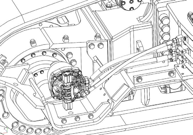
54 Assembly procedure Installation of travel motor pipingA-3 Precautions Tools required Equipment required 1)Take care that dirt will not enter the piping. 2)The hoses are installed to the travel motor. Name Q’ty Name Q’ty Air impact wrench 1 17 mm Socket 1 19 mm Socket 1 200 mm Extension 1 300 mm Extension 1 24 mm Spanner 1 41 mm Spanner 1 Others No.Part No.Parts nameQ'ty A-9 07000-B3048O-ring4 A-10 11Y-62-11980O-ring2 Connect hoses with O-rings (A-9) and (A-10). (Both side of L.H R.H) A-10 (2) ・Hoses are installed with travel motors when transported. ・ A-9 (4)


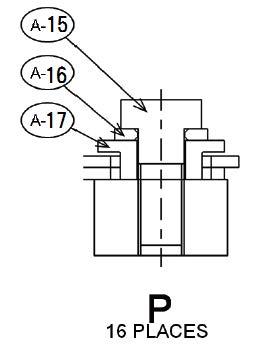
55 Assembly procedure Installation of travel motor cover (1/3)A-4 Precautions Tools required Equipment required Travel motor guard is installed to crawler frame assembly when transported. Travel motor cover is installed temporarily to crawler frame assembly when transported. a Before performing this item, bleed air from the travel motor. NameQ’tyNameQ’ty Others Crawler frame Travel motor cover Travel motor No.Partguard No.Parts nameQ'ty A-15 01010-82460Bolt16 A-16 01643-32460Washer16 A-17 21T-30-32370Collar16 Air impact wrench 1 Socket 36mm in width across flats 1
56 Assembly procedure Installation of travel motor cover (2/3)A-4 Precautions Tools required Equipment required Name Q’ty Name Q’ty Others Air impact wrench 1 Socket 36mm in width across flats 1 No.Part No.Parts nameQ'ty A-11 21T-30-32173-XCCover (LH)1 A-12 21T-30-32183-XCCover (RH)1 A-13 01010-82460Bolt10 A-14 17A-54-44130Washer10

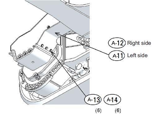
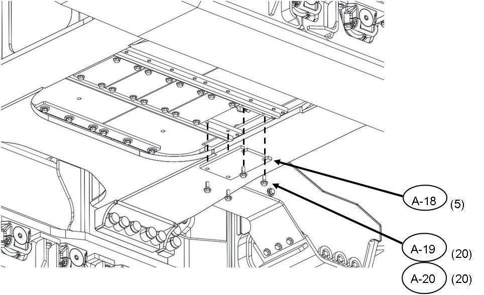
57 a This page is for only the center frame under cover speciflcation. Assembly procedure Installation of travel motor cover (3/3)A-4 Precautions Tools required Equipment required Install the center frame under cover after adjusting the hydraulic idler cushion. Name Q’ty Name Q’ty Others Front of machine Left of machine Machine from below No.Part No.Parts A-2021U-46-31270Washer20A-1901010-82465Bolt20A-1821T-30-48120-XCPlate5nameQ'ty Air impact wrench 1 Socket 36mm in width across flats 1

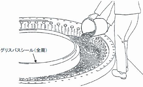
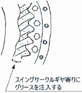
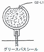
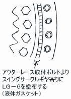
58 1)Fill the swing circle grease bath with grease (G2-LI). 2)Apply grease to the swing circle gear contact faces (Approx. 10 l (9 kg) of 80 l (72 kg)). 3)Fill the grease bath seal with grease. 4)Apply gasket sealant LG-6 to the swing circle mounting face. Assembly procedure Filling swing circle with greaseA-5 Precautions Tools required Equipment required •Supply 4 × 20 l (18 kg) cans of grease (G2-LI), 80 l (72 kg) in total. •Clean the swing circle mounting face. •Remove rust preventive. (If rust preventive is left, the bolt tightening torque reduces after the bolt is tightened.) Name Q’ty Name Q’ty Others Grease bath seal (all round) Supply grease near swing circle gear. Grease bath seal G2-LI Apply LG-6 (Gasket sealant) to swing circle gear side of outer race mounting bolts. G2-LI 1set LG-6 1set

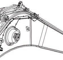
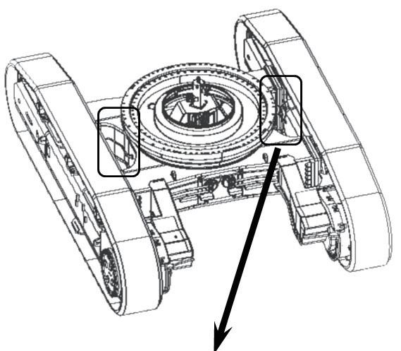
59 1)Positioning of crane and revolving frame 2)Method of slinging rear end Sling front and rear ends simultaneously with 2 truck cranes. Assembly procedure Assembly of revolving frame assembly and undercarriage (1/2)A-6 Precautions Tools required Equipment required a When slinging the revolving frame, adjust it to the horizontal in each direction with shackles. a Remove the rust preventive from the mounting faces of the revolving frame and swing circle and from the inside face of the taps and then clean those faces. (If any rust preventive is left, the bolt torque will be decreased.) Name Q’t Name Q’t See SC55above.shackle = 18 t (Inside width: 83 mm) SC40 shackle = 10 t Others Fix the ropes to the hook securely. Take care of the center of gravity of the crane hook. If the hook is loaded, the boom lowers a little. When installing revolving frame assembly to undercarriage, remove transportation jigs. Front side 20t Rear side 12t


60 Assembly procedure Assembly of revolving frame assembly and undercarriage (2/2)A-6 Precautions Tools required Equipment required Name Q’t Name Q’t Air impact wrench 1 155 mm Socket Tap (M36 × 3) 1 Others Fix the ropes to the hook securely. Take care of the center of gravity of the crane hook. If the hook is loaded, the boom lowers a little. a When disassembling to 27 t, install swing machinery later. a When disassembling to 32 t, raise the (Performmotor. this so that the machinery gear can be rotated freely and its phase can be set to that of the swing circle.) Dowel pin Width across flats 3 Tightening torque : 250 -- 310 kgm Apply LT-2. 55 Revolving frame assembly Apply LG-6 (TB1215) all round revolving frame coupling surface without leaving any breaks. (Apply to inside of bolt holes.) 3 Tightening torque : 2450 -- 3040 Nm {250 -- 300 kgm} Apply LT-2. Right LeftFront Rear a Sling horizontally so that pinion will not be damaged. No.Part No.Parts B-201643-33690Washer60B-121T-25-67150Bolt60nameQ'ty 1)Clean the mounting surface. 2)Align the dowel pin with the dowel pin hole of the swing circle. (Align it from the rear side machinery.) 3)Sling and couple the revolving frame. Take care not to hit it against the swivel joint and grease bath. 4)Tighten all the bolts lightly. • Retighten them after finishing assembly. 5)Tighten 3 bolts each of the right and left sides, 8 bolts on the front side and 3 bolts on the rear side (17 bolts in total) in the drawing to the specified torque. a Tighten to median of specified torque range
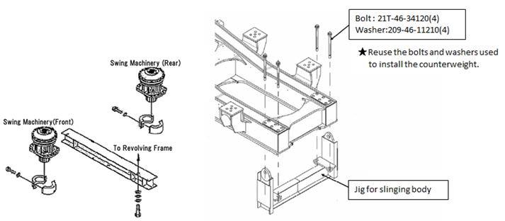
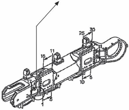
61 Assembly procedure Installation of swing machinery (front) assembly (27t) Installation of swing motor (front) assembly (32t)A-7 Precautions Tools required Equipment required a When connecting the revolving frame to the undercarriage, raise the swing motor assembly (front). (200 mm) After connecting the revolving frame to the undercarriage, reinstall the swing motor assembly. (When disassembled to 32 t) a Take care that the O-ring will not be caught. Name Q’ty Name Q’ty Air Impact wrench 1 46 mm Socket 1 Joint 1 14 mm Socket 1 19 mm Set wrench 1 19 mm Spanner 1 32 mm Set wrench 1 32 mm Spanner 1 22 mm Set wrench 1 22 mm Spanner 1 Swing machinery (front) assembly Swing motor (front) assembly 1,034 kg Connection at 5 Couplingplaces Front side Rear side No.Part No.Parts B-901024-81225Bolt1B-802896-61009O-ring1B-702896-61015O-ring1B-607000-B3032O-ring2B-507000-B3038O-ring1B-401643-33080Washer14B-301010-83090Bolt14nameQ'ty B-10 02896-61008O-ring 2


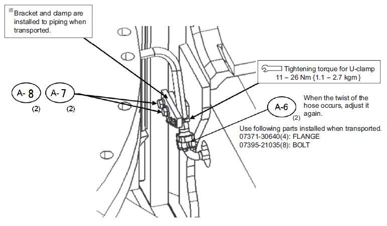
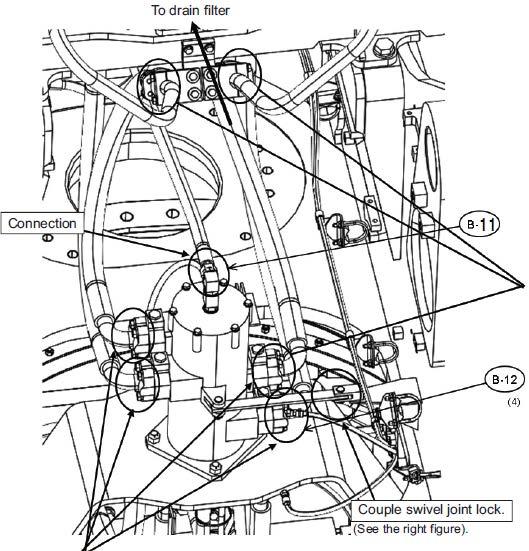
62 Assembly procedure Connection of swivel joint pipingA-8 Precautions Tools required Equipment required •Watch your step during work. (Take care not to drop oil around your feet.) •Take care not to catch the O-rings. (Check visually.) Name Q’ty Name Q’ty Air impact wrench 1 22 mm Socket 1 200 mm Extension 1 41 mm Spanner 1 Pincher or plier 1 Set wrench 1 Others Connection Plate Pin Cotter pin Washer No.Part No.Parts nameQ'ty B-11 B-1207000-B3048O-ring411Y-62-11980O-ring1 a It the twist or interference of the hose occurs, correct it. Use following parts assembly during transportation. 01643-31445(16):WASHER01010-81455(16):BOLT07371-51470(8):FLANGE Upper parts are installed at the swivel side. If installed angle is not proper, loosen opposite side and install again.

63 Assembly procedure Connection of swing circle grease pipingA-9 Precautions Tools required Equipment required Name Q’ty Name Q’ty 17 mm Spanner 1 19 mm Spanner 1 Others Connection
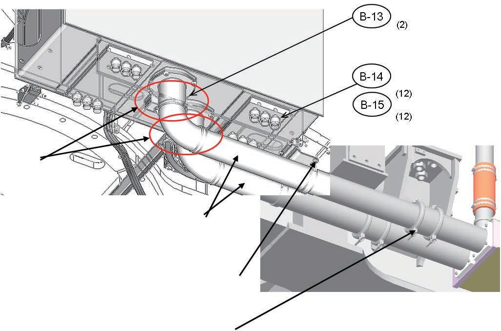
64 Assembly procedure Installation of hydraulic tank assembly (1/5)A-10 Precautions Tools required Equipment required a Before connecting the revolving frame to the undercarriage, install the hydraulic tank. Name Q’ty Name Q’ty Others Hydraulic tank assembly 1750Usekg bolts and washers installed when 01024-81235(8):transported. BOLT 3 Tightening torque : 1520 -- 1910 Nm {155 -- 195 kgm} Connection Suction tubes are installed temporarily to chassis when transported. 3 Tightening torque for U-clamp 35.3 -- 87.2 Nm {3.6 -- 8.9 kgm} 3 Tightening torque for coupling 6.4 -- 7.4 Nm {0.65 -- 0.75 kgm} No.Part No.Parts B-1521T-26-11460Washer12B-1401011-83010Bolt12B-1307000-B5230O-ring2nameQ'ty For disassembly to 27 t

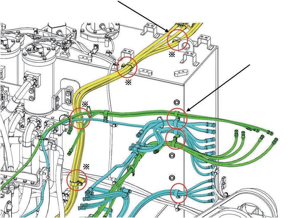
65 Assembly procedure Installation of hydraulic tank assembly (2/5)A-10 Precautions Tools required Equipment required Name Q’ty Name Q’ty Others For disassembly to 27 t Clamp air conditioner hoses at 4 places marked with . Clamp PPC hoses at 3 places marked with .
66 Assembly procedure Installation of hydraulic tank assembly (3/5)A-10 Precautions Tools required Equipment required Name Q’ty Name Q’ty Others Use split flanges and bolts installed when transported. 07371-32076(16): FLANGE 07375-21240(32): BOLT Connection at 5Clampplaceshose. No.Part No.Parts B-1607000-B2060O-ring8nameQ'ty For disassembly to 27 t

67 Assembly procedure Installation of hydraulic tank assembly (4/5)A-10 Precautions Tools required Equipment required Name Q’ty Name Q’ty Others Use split flanges and bolts installed when transported. 07371-31049(2): FLANGE 07375-21035(4): BOLT Connection at 4 Fromplacespower containerRear of main valve No.Part No.Parts B-1807000-B3032O-ring1B-1711Y-62-11980O-ring3nameQ'ty For disassembly to 27 t

68 Assembly procedure Installation of hydraulic tank assembly (5/5)A-10 Precautions Tools required Equipment required Precautions to be observed when connecting DT, DTP or DTHD connector • After connecting the connector, check visually that the connector is locked securely. If the connector is not locked securely, reconnect it. Name Q’ty Name Q’ty Others When locked When unlocked For disassembly to 27 t Clamp wiring harness (Side of vertical panel of revolving frame). Clamp wiring harness (L-bracket in cab base). Pull wiring harness into cab base through this grommet. CN-A13 Connect wiring harness connector (inside of cab base).
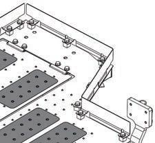
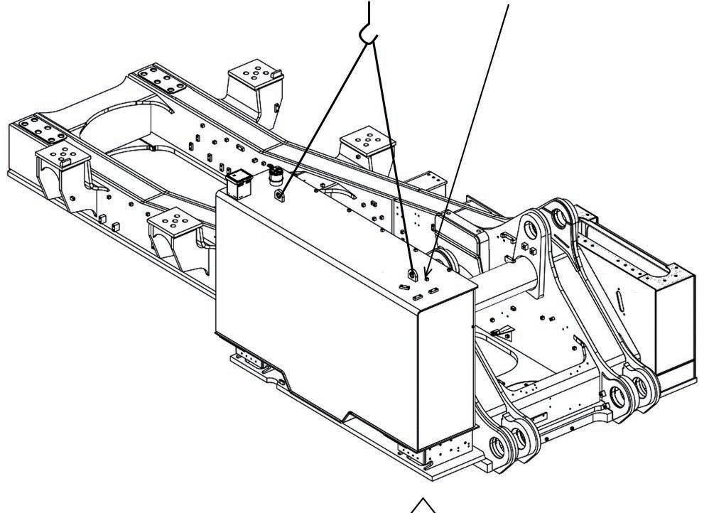
69 Assembly procedure Installation of fuel tank assemblyA-11 Precautions Tools required Equipment required Name Q’ty Name Q’ty Air Impact wrench 145t Crane 1 46 mm Socket 1 ø12 × 5 m Wire 2 Eyebolt M30-P3 2 Others 45 t Crane Fuel tank assembly 2150 kg BoltWasher No.Part No.Parts C-221T-26-11460Washer20C-101011-83010Bolt20nameQ'ty


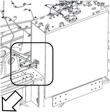
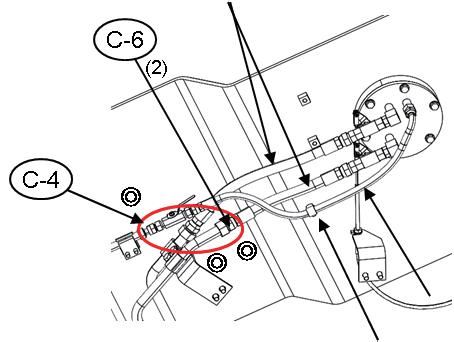
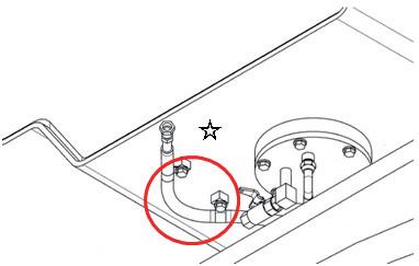
70 Fuel piping 1.Connection of return and spill lines 1)Remove the oil stoppers of the return and spill lines. 2)Connect the return and spill lines marked with ※ and fix them with the clamps. Assembly procedure Connection of fuel tank assembly piping and wiring (1/2)A-12 Precautions Tools required Equipment required Name Q’ty Name Q’ty 27 mm Spanner 1 32 mm Spanner 1 36 mm Spanner 1 19 mm Socket 1 Air Impact wrench Others Return line Band marker: Red Spill Bandlinemarker: None O-ring BoltClamp O-ring Delivery lineO-ring Reused clampDrainline No.Part No.Parts C-701024-81220Bolt1C-602896-61018O-ring2C-502896-61015O-ring2C-402896-61012O-ring1C-304435-52212Clip1nameQ'ty C-8 09460-00000Lock1 2.Connection of drain and supply lines 1)Remove the transportation clamps of the drain line marked with A Keep 1 of the 2 clamps to use in 3). 2)Remove the oil stoppers of the drain and supply lines. 3)Connect the drain and supply lines marked with w 3.Contact the wire. C8 1


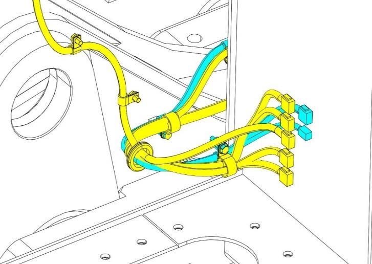
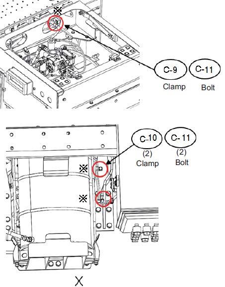
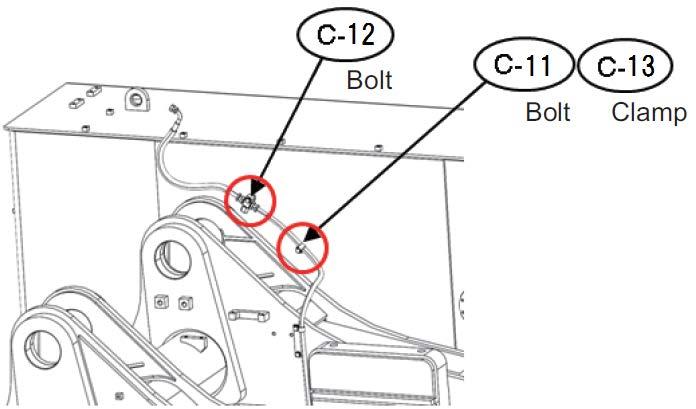
71 Electric wiring Assembly procedure Connection of fuel tank assembly piping and wiring (2/2)A-12 Precautions Tools required Equipment required Precautions to be observed when connecting DT, DTP or DTHD connector • After connecting the connector, check visually that the connector is locked securely. If the connector is not locked securely, reconnect it. Name Q’ty Name Q’ty Others When locked When unlocked CN-A24 1.Clamp the wiring harness to the grease can bracket. 4 places marked with 2.Connect the wiring harness connector marked with . No.Part No.Parts nameQ'ty C-9 04434-52312 Clip 1 C-10 04434-51912 2 C-11 01024-81220Bolt4 C-12 01024-81250Bolt1 C-13 04434-52112 1CCliplip
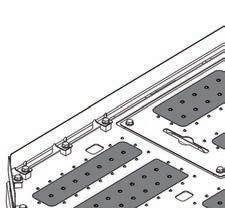
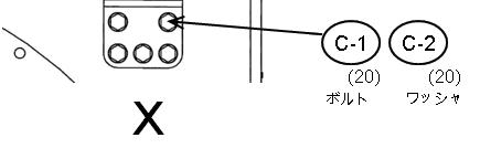
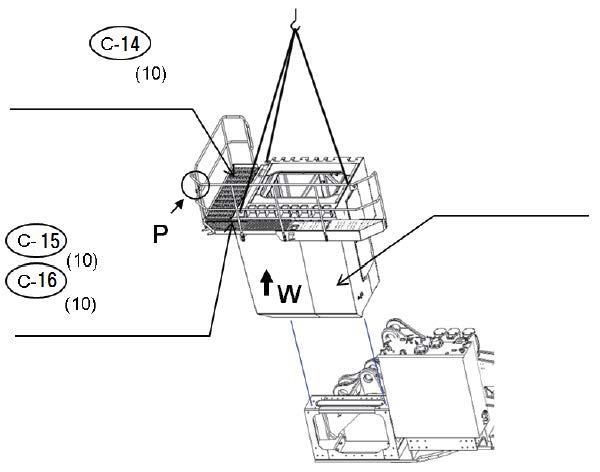
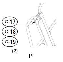
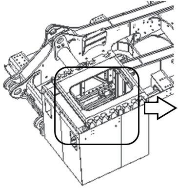
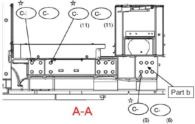
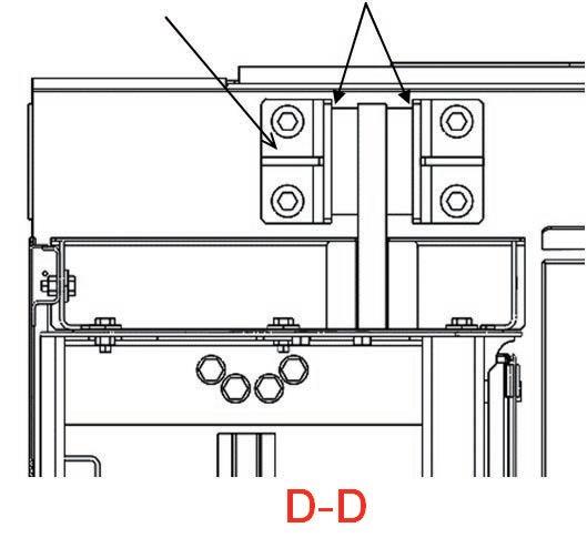
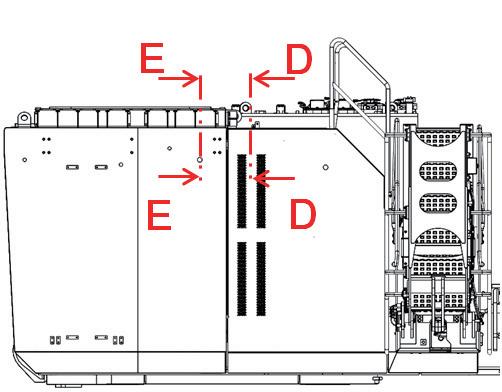
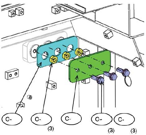
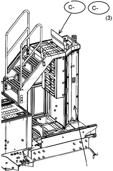
72 Assembly procedure Installation of cab base assembly (1/2)A-13 Precautions Tools required Equipment required •For the installed angle of the working lamp, see M-7. Name Q’ty Name Q’ty Air impact wrench 145t Crane 1 19 mm Socket 1 ø12 × 5 m Wire 3 SC14 Shackle 3 Others No.Part No.Parts nameQ'ty C-14 01034-81245Bolt10 C-15 01010-81680Bolt10 C-16 2A5-01-11590Washer10 C-17 21T-54-31140-XCClamp1 C-18 21T-54-31150-XCClamp1 C-19 01034-81245Bolt2 C-20 20Y-06-43230Working lamp ass'y2 C-21 21T-06-32820Working lamp ass'y1 C-22 04434-51012Clip12 C-23 01024-81220Bolt12 Cab base assembly 2600kg Catwalk in front of cab 100kg Mounting bolt to cab base assembly Mounting bolt to cab base assembly Catwalk on left of cab 220kg Before installing to cab base, install working lamp. W Q R C-20C-21 C-22 (12) C-23 (12) C-20 Marked ※ (See portion Q , R ) 24 mm Socket 1
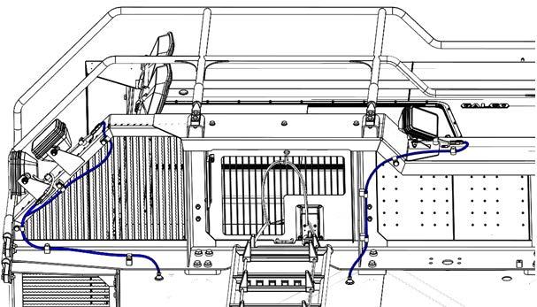
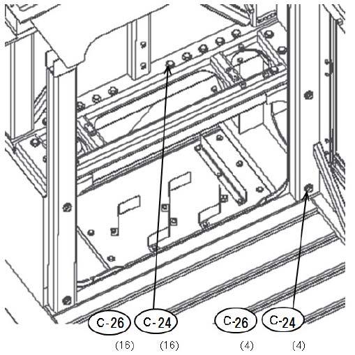
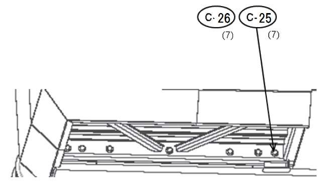
73 Assembly procedure Installation of cab base assembly (2/2)A-13 Precautions Tools required Equipment required Name Q’ty Name Q’ty Others No.Part No.Parts nameQ'ty C-24 01011-82035Bolt20 C-25 01011-82045Bolt7 C-26 567-40-41380Washer27 Q R ※※ ※※ ※ ※ ※※ ※ ※ ※ ※ Air impact wrench 1 30 mm Socket 1


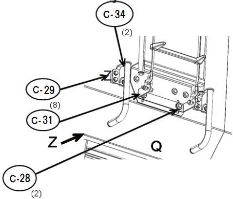
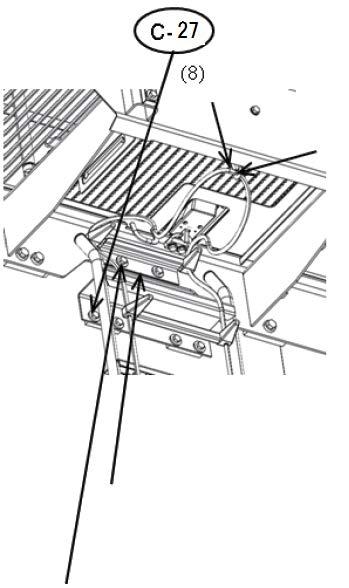
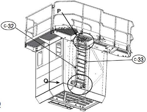
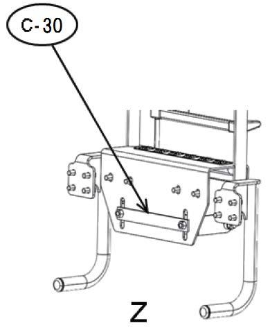
74 Assembly procedure Installation of emergency escape ladderA-14 Precautions Tools required Equipment required a Be sure to fix the rope ladder without looseness. a Be sure to install the snap ring of rope ladder to the hook of the escape door. Name Q’ty Name Q’ty Air Impact wrench 1 19 mm Socket 1 200 mm Extension 1 Others Fixed ladder assembly 25 kg No.Part No.Parts nameQ'ty C-27 01034-81225Bolt8 C-28 01034-81225Bolt2 C-29 01024-81225Bolt8 C-30 21T-54-37690-XCBracket1 C-31 21T-54-37621-XCBracket1 C-32 21T-54-37661-XCLadder1 C-33 21T-54-37681Ladder1 C-34 21T-53-33141-XCHandrail2Ropeladder3kgHandrailassembly2kgBracket for adjusting tension of rope ladder To be connected with rope ladder 1 Mountingkgbolts for handrail assembly Mounting bolt of bracket for adjusting tension of rope ladder Mounting bolts for fixed ladder assemblyBracket for adjusting tension of rope ladder Mounting bolt of bracket for adjusting tension of rope ladder (Factory fitted temporaly) 1 kg Snap ring (rope ladder) Hook (escape door) Mounting bracket of rope ladder tensioner bracket 0.35kg
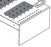
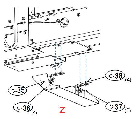
75 Assembly procedure Installation of left floor assembly (1/5)A-15 Precautions Tools required Equipment required After the work, return the bolts removed to install the eyebolts. Name Q’ty Name Q’ty Others Sling position Install eyebolt. M24 (4Leftplaces)floor assembly 2,100 kg No.Part No.Parts nameQ'ty C-35 21T-54-43370-NKCover1 C-36 01034-81240Bolt4 C-37 21T-53-32820-NKBracket2 C-38 01034-81240Bolt4 Z stalling exterior parts, their level difference with se shims. (See A-47.)thethinine Air impact wrench 1 Socket 19mm in width across flats 1


76 Assembly procedure Installation of left floor assembly (2/5)A-15 Precautions Tools required Equipment required Before tightening the mounting bolts at parts (a) and (b), check that both mating faces are fitted to each other. Tightening torque of mounting bolts (C-41, C43. C-45): 883 - 980 Nm {90 - 100 kgm} Tightening torque of a mark mounting bolts: 235 - 285 Nm {23.5 - 29.5 kgm} Name Q’ty Name Q’ty Others No.Part No.Parts nameQ'ty C-39 01010-82075Bolt9 C-40 15R-70-16370Washer9 C-41 01011-82470Bolt1 C-42 21T-54-43820Washer1 C-43 01010-82470Bolt11 C-44 21T-54-43810Washer17 C-45 01010-82480Bolt6 Align each condenser box tap center with cab base mounting hole center by adjusting bolts marked with a and A Air impact wrench 1 Socket 30 mm in width across flats 1 Socket 36 mm in width across flats 1 39 40 44 45 41 42 43 44
77 Assembly procedure Installation of left floor assembly (3/5)A-15 Precautions Tools required Equipment required Name Q’ty Name Q’ty Others No.Part No.Parts nameQ'ty C-46 21T-54-44570Plate1 C-47 21T-54-44550Spacer3 C-48 21T-54-44560Plate1 C-49 01010-81655Bolt3 C-50 01643-31645Washer3 This part is installed to the cab base before shipment ,so remove and adjust it. No clearance Air impact wrench 1 Socket 24 mm in width across flats 1 46 47 48 49 50
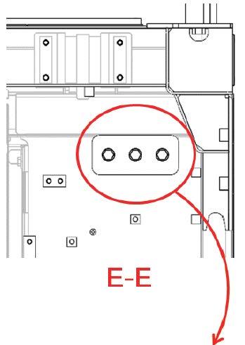
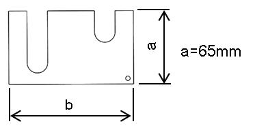
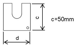
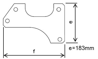
78 Assembly procedure Installation of left floor assembly (4/5)A-15 Precautions Tools required Equipment required Name Q’ty Name Q’ty Others After installing exterior parts, adjust their clearance and level difference with these shims. (See A-47) Adjust clearance at this part, if necessary, by inserting shim under condenser box and lower part of cab rear ladder. C-56 Clearance: 15 ± 10mm Shim (C-51) t1.2 Shim (C-52) t1.2 Shim (C-53) t1.2 Plate (C-56) t4.5 No.Part No.Parts nameQ'ty C-51 21T-53-32271-SAShim6 C-52 21T-53-32350-SAShim10 C-53 21T-54-41241Shim3 C-54 21T-54-43570-XCCover1 C-55 01034-81230Bolt,sems3 C-56 d=50mmc=50mm21T-53-32280-SAPlate6a=65mmb=109mme=183mmf=280mmg=70mmh=200mm Air impact wrench 1 Socket 19 mm in width across flats 1 C51 C52 C53 (6) (10) (3) 54 55 When assembling this assembly, adjust is so that it will not interfere with cab base door.Y (Positon of shims ; See the next page in detail) X


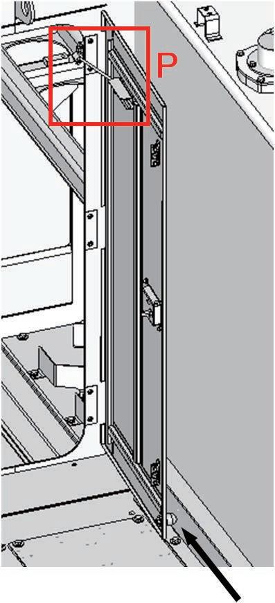
79 <Adjustment of cab base door> Adjust the projection of rubber stopper (a) at the door bottom and position of lock bar bracket (c) so that lock bar (b) at the door top will clasp while rubber stopper (a) is in contact with the side cover. Assembly procedure Installation of left floor assembly (5/5)A-15 Lock bar bracket (c) Rubber stopper (a)P C-52C-51 XC-53 Lock bar (b)

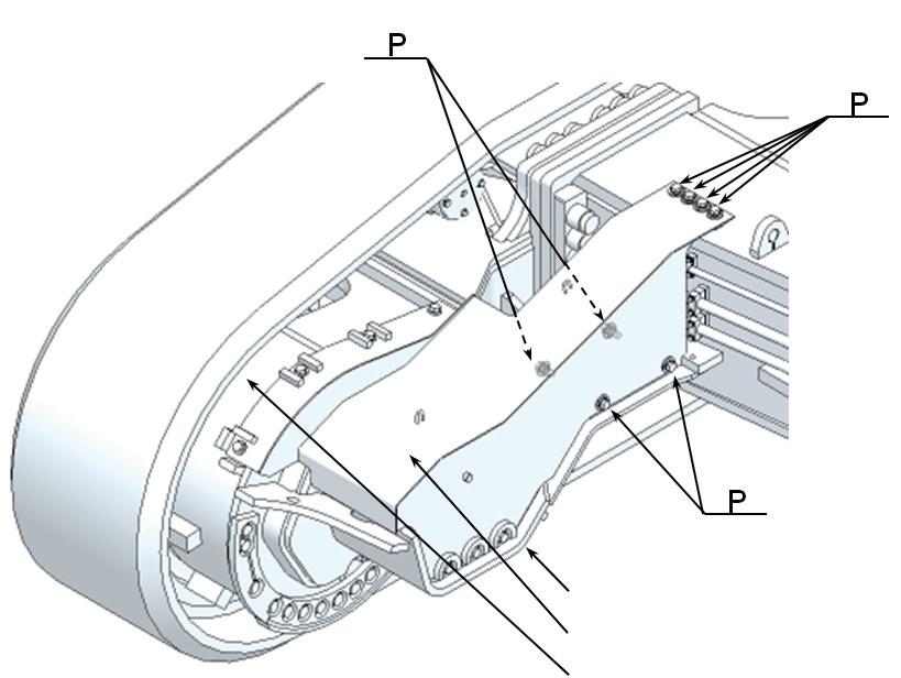
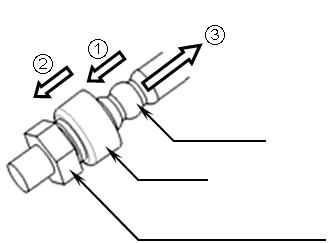
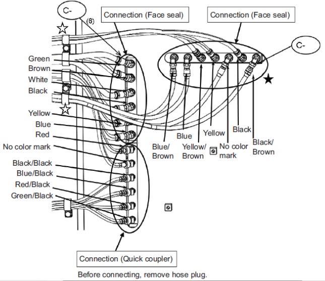
80 Assembly procedure Connection of cab base assembly piping (1/3)A-16 Precautions Tools requiredEquipment NameQ’tyNameQ’tyrequired Others Disconnection of quick coupler (1) Push the hose adapter into the adapter. (2) Push the cap into the adapter. (3) Pull the hose straight. Hose adapter Hose Adapter (Plug or joint)AdapterCap (Plug or joint) Connection of quick coupler (4) Hold the hose adapter and push it straight into the adapter until it clicks. After connecting the hose, pull its adapter lightly to check that it will not come off. No.Part No.Parts nameQ'ty C-57 02896-61012O-ring6 C-58 02896-61009O-ring 7 Spanner 1 57 58(7) P P

81 Assembly procedure Connection of cab base assembly piping (2/3)A-16 Precautions Tools required Equipment required Name Q’ty Name Q’ty Others Spanner 1 No. Part No. Parts name Q'ty C-59 02896-61018 O-ring 2 C-60 02896-61012 O-ring 1 For #06 . 90° fitting 59For #06 . Straight fitting (Right wall in cab base from the previous page) 60For #04 . fittingStraight Connect hoses
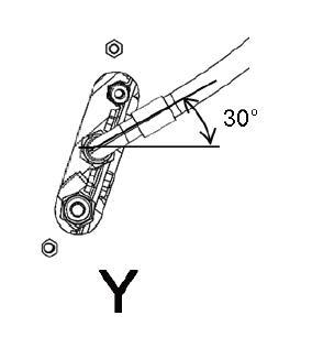
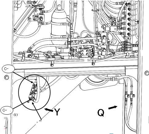

82 Assembly procedure Connection of cab base assembly piping (3/3)A-16 Precautions Tools required Equipment required Name Q’ty Name Q’ty Others No.Part No.Parts nameQ'ty C-61 04435-52112Clip 2 C-62 01024-81225Bolt 1 C-63 154-979-1480Collar1 C-64 01024-81275Bolt1 C-65 01024-81025Bolt2 Air impact wrench 1 Socket 17 mm in width across flats 1 Socket 19 mm in width across flats 1 Clamp the hose. (Bracket and clip are temporarily installed to revolving frame. After clamping, install them to the specified torque. Q (Right rear in cab base from the previous page) 63646161 6562(2) Extension L200 1
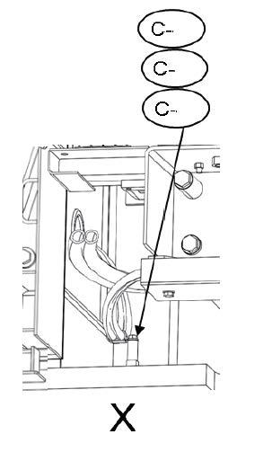
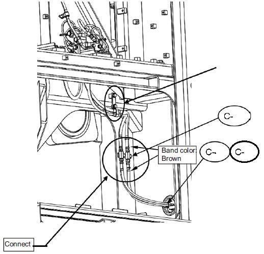

ConnectionPass
through
• When connecting HD multi-pole connector, see "Precaution for connecting HD multi-pole connector" on page 6/7 of this section. Pass wiring harness through hole. wiring harness hole.
Name Q’ty Name Q’ty Others
83 Assembly procedure Connection of cab base assembly wiring (1/7)A-17 Precautions Tools required Equipment required
•When connecting the SRC multi-pole connector, see "Precautions for connecting MOLEX multi-pole connector" on pages 6/7 of this section.
• When connecting the DRC multi-pole connector, see "Precautions for connecting DRC multi-pole connector" on pages 3/7 – 5/7 of this section.
CN-A04CN-A05CN-A92

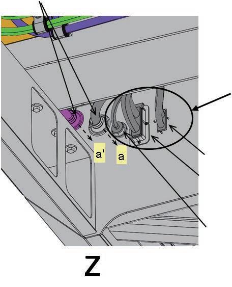
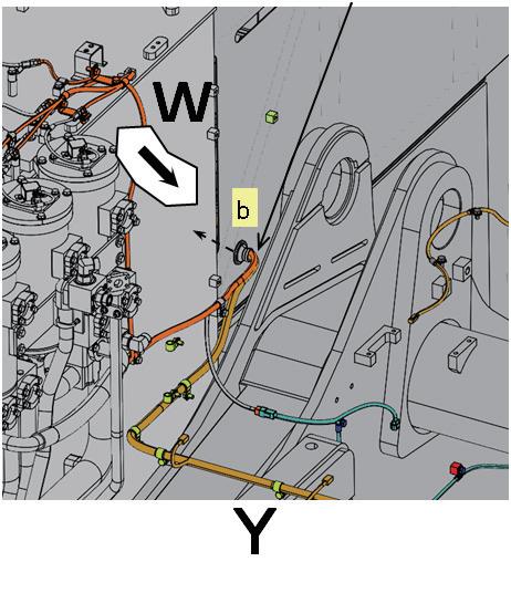
84 Assembly procedure Connection of cab base assembly wiring (2/7)A-17 Precautions Tools required Equipment required •When connecting the DT, DTP or DTHD connector, see "Precautions for connecting DT, DTP or DTHD connector" on pages 5/7 of this •Removesection.thecover of part X when connecting the wiring harness and install it again after the work. Name Q’ty Name Q’tyConnectionOthers No.Part No.Parts nameQ'ty C-66 01024-81020Bolt1 C-67 04434-52312Clip1 C-68 01024-81225Bolt1 C-69 04434-52712Clip2 C-70 01024-81225Bolt2 Service center specification Additional emergency stop switch specification Service center specification Standard specification Connect to ground Air impact wrench 1 Socket 19 mm in width across flats 1 Socket 17 mm in width across flats 1 X (From previous page) 66 (From previous page) 68 67 69 70
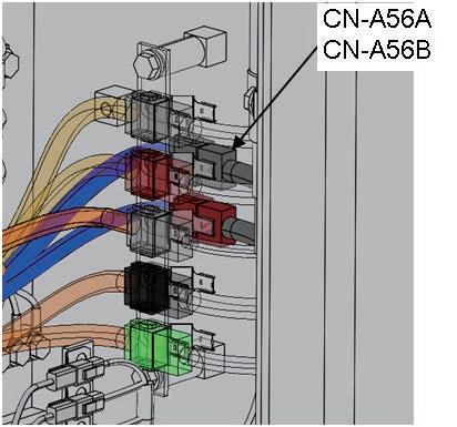
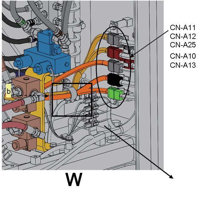


85 "Precautions for connecting DRC multi-pole connector" Precautions to be observed when connecting DRC multi-pole connector 1.Before 2.PreparationconnectingforconnectionIftheDRCmulti-poleconnector is at a high place, prepare a work stand so that you can stand stably and connect the connector while checking it visually. Assembly procedure Connection of cab base assembly wiring (3/7)A-17 Precautions Tools required Equipment required Name Q’ty Name Q’ty Others If the seal rubber is broken or deformed, the connector may not be connected normally. In this case, replace the connector with new one. 17A-06-4184017A-06-41830 Check the edge for breakage or deformation. If it has any abnormality, replace the whole connector with new one.
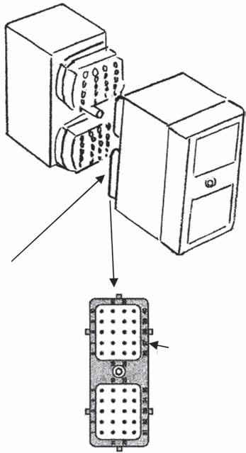
1)Check that the key ways are aligned and then set the terminals to each other while setting the seal rubber edge to the receptacle connector edge. While swinging the connectors up and down and to the right and left so that the terminals will be in position and clearance "a" and "b", and "c" and "d" between the connectors will be the same respectively, tighten the center hexagon socket head bolt 1 turn.
86 3.Connecting method
Assembly procedure Connection of cab base assembly wiring (4/7)A-17 Precautions Tools required Equipment required Name Q’ty Name Q’ty Others Receptacle connector edge Seal rubber edge Terminal DownUp LeftRightHexagon socket head bolt Side view Bottom view
2)While swinging the connectors up and down and to the right and left again to adjust them finely so that clearance "a" and "b", and "c" and "d" between the connectors will be the same respectively, tighten the bolt gradually. Repeat this work several times.
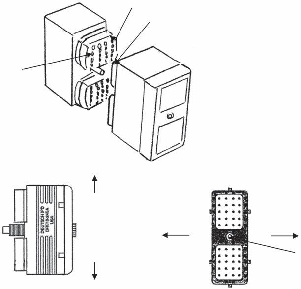
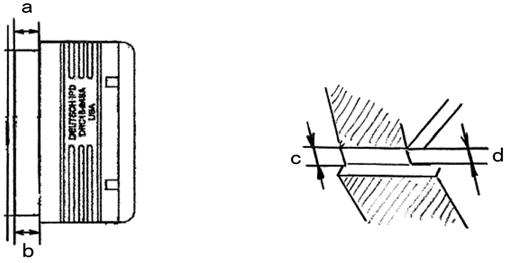
87 3)After clearances "a" and "b", and "c" and "d" between the connectors become the same and below 1 mm, tighten the hexagon socket head bolt to the following torque. 4)Check after connection • Turn the key switch ON and check that the electric parts of the chassis are operating normally. (Observe the condition for several minutes after turning the key switch ON.) • Start the engine, move the work equipment, and check that the electric parts (monitors and lights) do not blink because of vibrations. If any abnormality is detected by the above 2 checks, disconnect the connector and check it for a problem, and then repeat steps 1 - 3. "Precautions for connecting DT, DTP or DTHD connector" Precautions to be observed when connecting DT, DTP or DTHD connector • After connecting the connector, check visually that the connector is locked securely. If the connector is not locked securely, reconnect it. Assembly procedure Connection of cab base assembly wiring (5/7)A-17 Precautions Tools required Equipment required Name Q’ty Name Q’ty Others Approx. 1 mm 2.83 ± 0.28 Nm {0.28 ± 0.03 kgm} When locked When unlocked

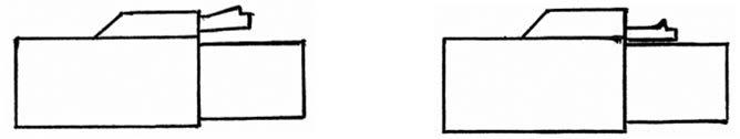
88 "Precautions for connecting SRC multi-pole connector" Assembly procedure Connection of cab base assembly wiring (6/7)A-17 Precautions Tools required Equipment required Name Q’ty Name Q’ty Others 1.Connecting method • Check that the receptacle connector lever is extended. Set the lever pin in the plug connector guide, and insert the receptacle connector. Then, push down the lever until it clicks, and the connectors are connected. • After connecting the connector, check visually that the connector is locked securely. If the connector is not locked securely, reconnect it. "Precautions for connecting DT multi-pole connector" 1.Connecting method • Set the receptacle connector guide pin in the plug connector guide, and insert the receptacle connector. Then, tighten the screw on the plug side. (Tightening torque: 4.85 ± 0.54 Nm) PushPindown lever. Guide LeverLeverPin Guide Receptacle connectorPlugconnectorLever ReceptacleGuideconnectorpinPlugGuideconnector
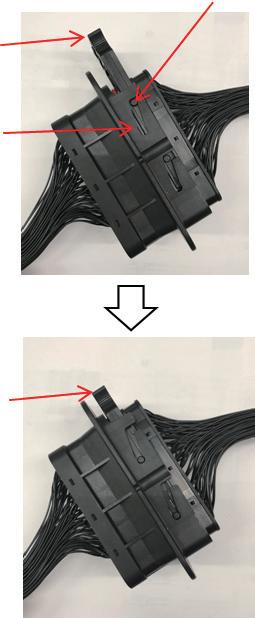
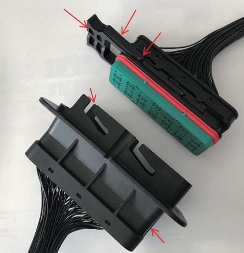

89 a This page is for only the hydraulic ladder specification. Assembly procedure Connection of cab base assembly wiring (7/7)A-17 Precautions Tools required Equipment required Name Q’ty Name Q’ty Others Left rear in cab base No.Part No.Parts nameQ'ty C-71 20Y-06-43230 1 C-72 01024-81285Bolt4 C-73 04434-51012Clip1 C-74 04434-51412Clip3 C-75 04434-51712Clip 2 C-76 04434-51912Clip2 C-77 01024-81225Bolt 7 C-78 04434-52312Clip1 C-79 175-40-22540Spacer1 C-80 01024-81275Bolt1 Left rear out of cab base Working lamp ass y Tighten together with KomVision harness. Air impact wrench 1 Socket 19 mm in width across flats 1 7275 (2)77 (2) 7677 7477 717377 A - A A A
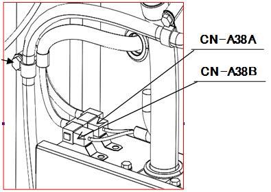
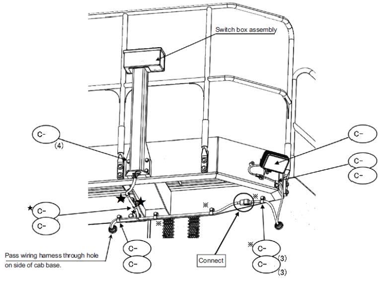
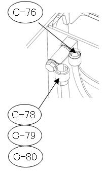
90 Assembly procedure Connection of left floor assembly heater pipingA-18 Precautions Tools required Equipment required When connecting the hoses, match their identification tape colors. Name Q’ty Name Q’ty Others No.Part No.Parts nameQ'ty C-81 07281-00419Clamp2Z 81 Socket 7 mm in width across flats 1Air impact wrench 1 Extension L200 1
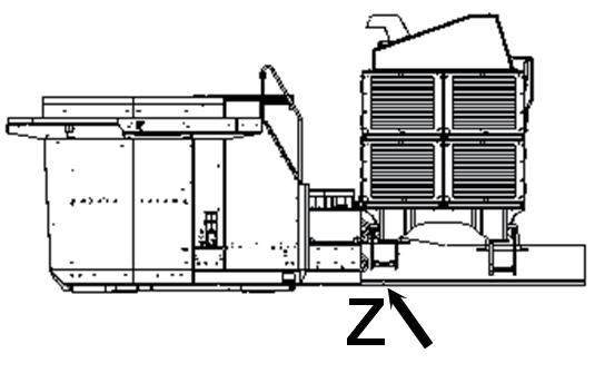
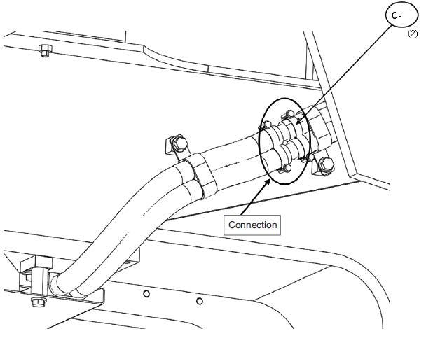
91 Assembly procedure Connection of left floor assembly wiring (1/2)A-19 Precautions Tools required Equipment required Precautions to be observed when connecting DT, DTP or DTHD connector • After connecting the connector, check visually that the connector is locked securely. If the connector is not locked securely, reconnect it. Name Q’ty Name Q’ty Others When locked When unlocked Front of machine Left of Connectionmachine Connection To cab This cable is described in A-31. To condenserconditionerair Right side of battery caseTop of air conditioner condenser No.Part No.Parts nameQ'ty C-82 01024-81025Bolt1 P P 82 Socket 17 mm in width across flats 1 Air impact wrench 1 X

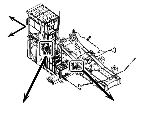

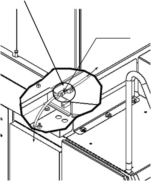
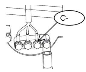
92 Assembly procedure Connection of left floor assembly wiring (2/2)A-19 Precautions Tools required Equipment required Name Q’ty Name Q’ty Others No.Part No.Parts nameQ'ty C-83 01024-81220Bolt1 C-84 04434-51012Clip1 8384 Socket 17 mm in width across flats 1 Air impact wrench 1 X Extension L200 1
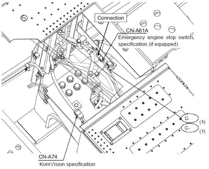
93 Assembly procedure Installation of tail pipeA-20 Precautions Tools required Equipment required a Before performing this work, connect the power module to the revolving frame. Name Q’ty Name Q’ty Others Top of power module Front of machine Left of machine No.Part No.Parts nameQ'ty D-0121M-01-18130Tail D-0521T-01-41951-XCCover2D-046162-14-5640RainD-0317A-54-42370Washer12D-0201010-D1240Bolt12pipe2cap2 Socket 19 mm in width across flats 1 Air impact wrench 1 Extension L200 1
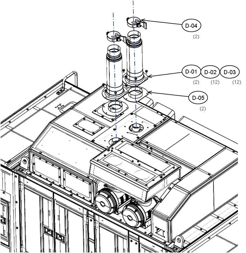

94 Assembly procedure Installation of power module assembly (1/2)A-21 Precautions Tools required Equipment required a Be careful not to fall down yourself. a Before installation, drain remaining oil from piping. Name Q’ty Name Q’ty Others Power module assembly 16800 kg Right rear Left rear Take care that mounting section of power module will not go over guide. ・Install bolts(*) to the installation hole before installing power container for ease of transportation of heavy equipment. Bolts (*); See next page

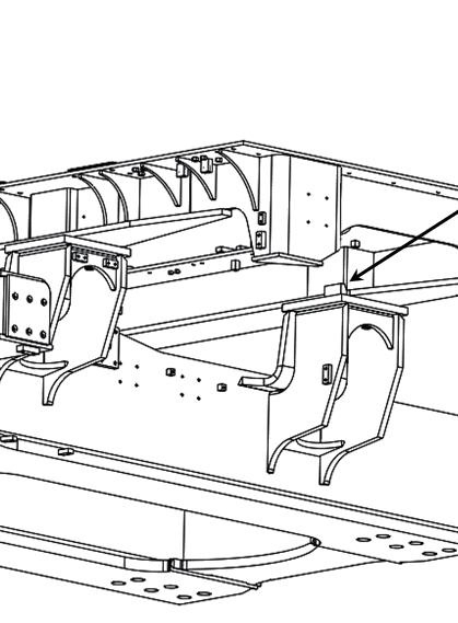


95 Assembly procedure Installation of power container assembly (2/2)A-21 Precautions Tools required Equipment required Retighten the bolts finally after installing the counterweight for safety. After assembling, check securely that all the bolts are tightened to the specified torque. Name Q’ty Name Q’ty Others 3,430 – 4,212 Nm {350 – 430 kgm} No.Part No.Parts nameQ'ty D-6 21T-54-31121-NKPlate4 D-7 21T-54-31130Bolt20 D-8 01643-34212Washer20 M42 × 3, L = 350 mm, Width across flats 65 mm 3 Tightening torque : 8 7 6 Socket 65 mm in width across flats 1 Air impact wrench 11Hydlaulic wrench (with pump)
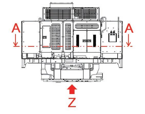

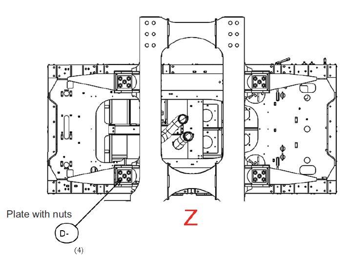
96 Assembly procedure Connection of suction piping (1/2)A-22 Precautions Tools required Equipment required •Do not loosen the clamp band on the suction sub-tank side. Name Q’ty Name Q’ty Others No.Part No.Parts nameQ'ty D-9 07000-B2140O-ring2 D-10 07000-B2100O-ring1 D-11 209-62-41341Clamp4 D-12 20Y-62-51671Clamp2 mp seenMain pump seen from belowf 9 10 11 12 Socket 13 mm in width across flats 1 Extension L200 1 Socket 15 mm in width across flats 1 Air impact wrench 1
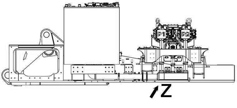


97 1.Once a MIKALOR clamp is removed, do not use it again but replace it with new one. 2.Install MIKALOR clamp marked as shown below. (1)Adjust bridge position so that the bridge shoud go into the bottom of band of clamp as shown in the following figure. (2)Tighten bolt so that dimension (a) should be below figure by using impact wrench. Assembly procedure Connection of suction piping (2/2)A-22 Bridge Apply lubricating oil (PANDO 18B made by Three Bond) on thread of bolt before tightening a bolt. Punch hole The overlap of bridge and band. No.1 209-62-4134115 -30 2 20Y-62-51671 20 -30 Clamp part No. Dimension (a) a
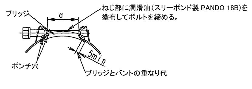
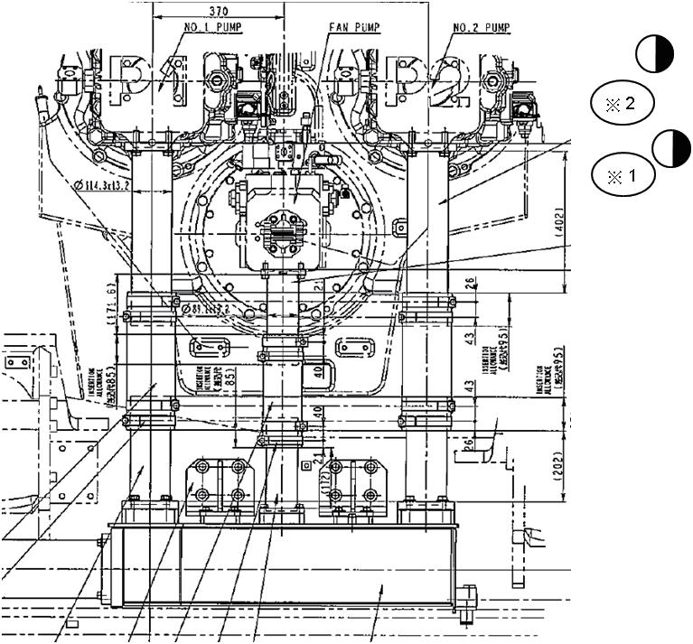
98 Assembly procedure Connection of oil cooler piping and pump drain pipingA-23 Precautions Tools required Equipment required Take care that the O-ring will not be caught. When connecting ※ marked parts, keep the 1.Loosenfollowings.temporary installed parts of straight fitting side. 2. Fix the 45 fitting side to the specified 3.Tightenangle. the temporary installed part of straight fitting side to the specified torque. Name Q’ty Name Q’ty Others Use following parts installed when transported. 07371-32076(8): FLANGE 07371-31465(8): 07375-21240(32):FLANGEBOLT No.Part No.Parts nameQ'ty D-13 07000-B2060O-ring4 D-14 07279-02011Hose1 D-15 07000-B3048O-ring4 1314 1315 Socket 19 mm in width across flats 1 Extension L200 1 Air impact wrench 1 (Both sides are 45°fitting hoses) Tighten bolts of clamps after hoses installed.Direction of 90° fitting hose (Tighten this fitting sides at first, then tighten straight fitting side with specifiedDirectiontorque.)of45° fitting hose (※ part) (Tighten this fitting sides at first, then tighten straight fitting sides with specified torque.)

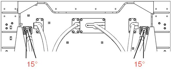

99 Assembly procedure Connection of fan motor drain pipingA-24 Precautions Tools required Equipment required Name Q’ty Name Q’ty Others No.Part No.Parts nameQ'ty D-16 07000-B3032O-ring1 16 Socket 19 mm in width across flats 1 Extension L200 1 Air impact wrench 1
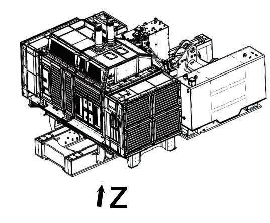
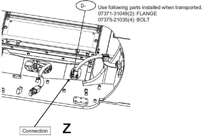
100 Assembly procedure Installation of suction unit undercoverA-25 Precautions Tools required Equipment required Name Q’ty Name Q’ty Others D-29 01024-81235 Bolt 3 No. Part No. Parts name Q'ty D-17 21T-54-34931-NK Frame 1 D-18 21T-54-42590-NK Cover 1 D-19 21T-54-34991-NK Cover 1 D-20 21T-54-42580-NK Cover 1 D-21 21T-54-42520-NK Cover 1 D-22 21T-54-34961-NK Cover 1 D-23 21T-54-42530-NK Cover 1 D-24 203-54-62670 Collar 2 D-25 01024-81225 Bolt 2 D-26 01034-81225 Bolt 26 D-27 21T-54-34920-NK Cover 1 D-28 01024-81225 Bolt 2 27 28 29 18 26 19 26 20 26 24 25 26 17 26 21 26 22 26 23 (2) Socket 19 mm in width across flats 1 Extension L200 1 Air impact wrench 1 ● ◎ ● ● ◎ ◎ ◎
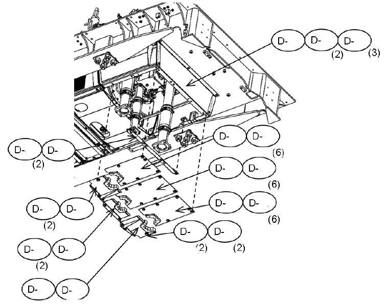


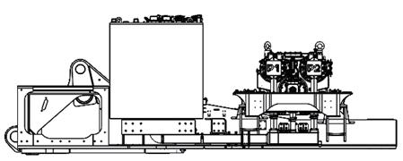


101 Assembly procedure Connection of delivery piping (1/3)A-26 Precautions Tools required Equipment required Name Q’ty Name Q’ty Others Before starting this work, remove covers temporarily. After connecting piping, install covers again. Socket 19 mm in width across flats 1 Extension L200 1 Air impact wrench 1
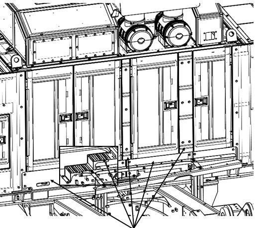
102 Assembly procedure Connection of delivery piping (2/3)A-26 Precautions Tools required Equipment required a Secure the scaffoldings. NameQ’tyNameQ’ty Others D-30 Left of machine Front of machine Front end of power module Connection Use following parts installed when No.Part01643-31445(16):01010-81455(16):07371-51470(8):transported.FLANGEBOLTWASHERNo.PartsnameQ'ty D-30 07000-B3048O-ring4Connectfrom(A)side Socket 19 mm in width across flats 1 Extension L200 1 Air impact wrench 1

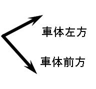


103 Assembly procedure Connection of delivery piping (3/3)A-26 Precautions Tools required Equipment required a Secure the scaffoldings. NameQ’tyNameQ’ty Others D-31 Right of machine Rear of machine Connection Rear of powermodule No.Part No.Parts nameQ'ty D-31 02896-61012O-ring1 Socket 19 mm in width across flats 1 Extension L200 1 Air impact wrench 1
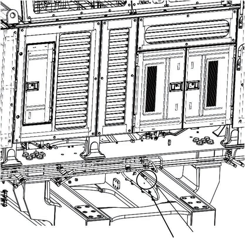

104 Assembly procedure Connection of pilot piping and fan motor pipingA-27 Precautions Tools required Equipment required Name Q’ty Name Q’ty Others Left of machine Front of machineFrLeo No.Part No.Parts nameQ'ty ※ D-32 07000-B3025O-ring2 D-33 07000-B3032O-ring1 Socket 19 mm in width across flats 1 Extension L200 1 Air impact wrench 1 3233


105 Assembly procedure Connection of power module assembly fuel piping (1/2)A-28 Precautions Tools required Equipment required 3 Tightening torque for hose A: 177 – 245 Nm {18 – 25 kgm} B: 128 – 186 Nm {13 – 19 kgm} Name Q’ty Name Q’ty Others Spill Delivery 1 Delivery 2 Delivery 2 (toReturnrear of container) SpillDeliveryReturn1 No.Part No.Parts nameQ'ty D-34 02896-61018O-ring2 D-35 02896-61015O-ring1 When installing fittings, loosen fittings and clamps at location marked with a so that fittings are not BAAtwisted. D35 D34 D34 Spanner 2
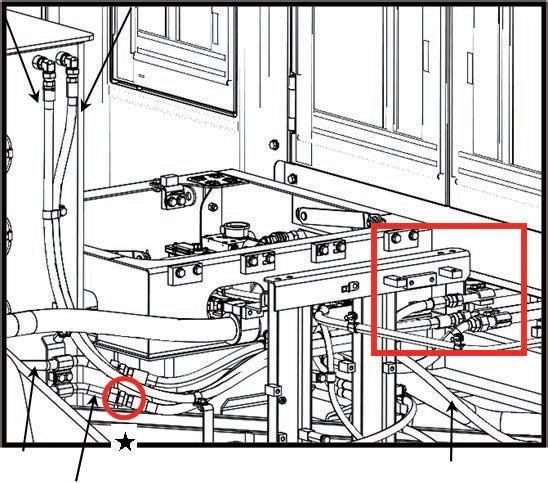


106 Assembly procedure Connection of power module assembly fuel piping (2/2)A-28 Precautions Tools required Equipment required Name Q’ty Name Q’ty Others No.Part No.Parts nameQ'ty D-36 02896-61015O-ring1 36 Spanner 2
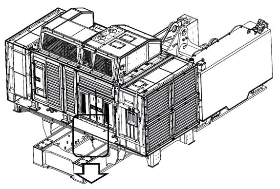
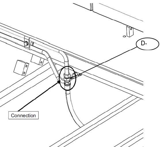
107 Assembly procedure Connection of power module assembly air conditioner pipingA-29 Precautions Tools required Equipment required 1.To prevent moisture and foreign matter from entering the air conditioner piping, ・ Do not perform this work on a rainy day. Always remove each blind plug just before piping work and perform the work quickly. ・ Never work with cotton work gloves on. 2.Apply compressor oil to the O-rings. ・ Be sure to use compressor oil for refrigerant R134a. ・ Never use oil or grease for other refrigerants. 3.Before connecting, check that the contact surfaces of the O-rings are free from dirt etc. 4.Using two spanners, tighten to the specified torque. (to prevent the damage of piping) Name Q’ty Name Q’ty Others No.Part No.Parts nameQ’ty E-40 21N-979-8160Oil compressor1 Parts to be removed M24 (Width across flats: 27) Container side is female. Tightening torque 30 - 35 Nm Apply compressor oil to the O-rings. (to prevent the lowering of sealing performance) M24 (Width across flats: 27) Container side is male. Tightening torque 30 - 35 Nm M22 (Width across flats: 24) Container side is male. Tightening torque 20 - 25 Nm M22 (Width across flats: 24) Container side is female. Tightening torque 20 - 25 Nm a 4. Female side is to be fixed.Connection Spanner 2 E40
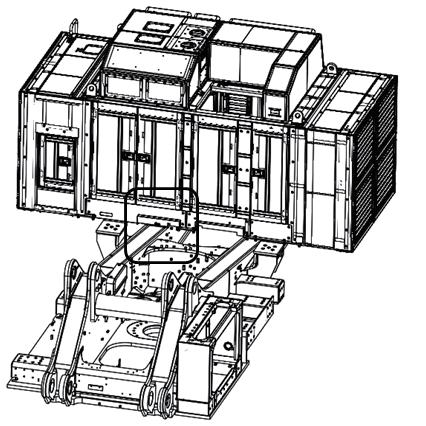
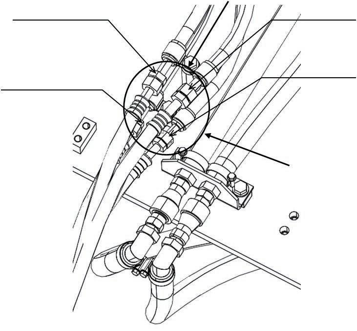
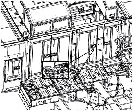

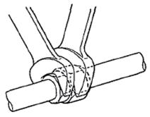
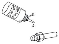
108 Assembly procedure Connection of power module assembly heater pipingA-30 Precautions Tools required Equipment required a Before connecting these hoses, connect all of the other heater hoses. Name Q’ty Name Q’ty Others Connection (Quick coupler) Parts to be removed

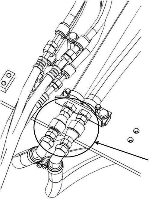
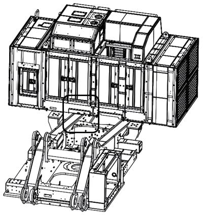
109 Assembly procedure Connection of power module assembly wiring (1/4)A-31 Precautions Tools required Equipment required Name Q’ty Name Q’ty Others Connect<Caution>the battery cable after all the wiring harnesses are connected. Front of machineLeft of machine To ground seat of revolving frame vertical plate FixConnection2terminals together. Connection No.Part No.Parts nameQ'ty D-37 08038-10035Cap 4 D-38 08038-04030Cap 4 37 38 Spanner 1
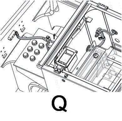


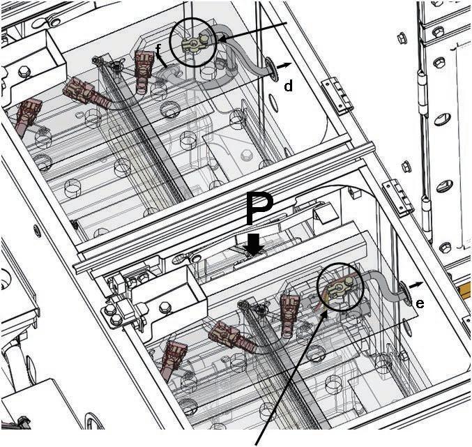


110 Assembly procedure Connection of power module assembly wiring (2/4)A-31 Precautions Tools required Equipment required Precautions to be observed when connecting DT, DTP or DTHD connector • After connecting the connector, check visually that the connector is locked securely. If the connector is not locked securely, reconnect it. Name Q’ty Name Q’ty Others When locked When unlocked Left of machine Front of machine No.Part No.Parts nameQ'ty D-39 08028-55065Wire2 D-40 01024-81020Bolt2 Socket 17 mm in width across flats 1 Extension L200 1 Air impact wrench 1 39 40 39 40
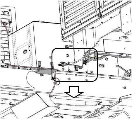


111 a This page is for isolator installed specification only. Assembly procedure Connection of power module assembly wiring (3/4)A-31 Precautions Tools required Equipment required Name Q’ty Name Q’ty Others MachineMachineleftfront Install InstallConnectioncaps.caps.Connection To revolving frame vertical board grounding seat (See A-19.) No.Part No.Parts nameQ'ty D-41 01024-81020Bolt4 For jump start installed specification, tighten 2 terminals together. 41 41 41 41

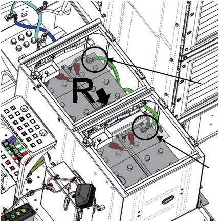
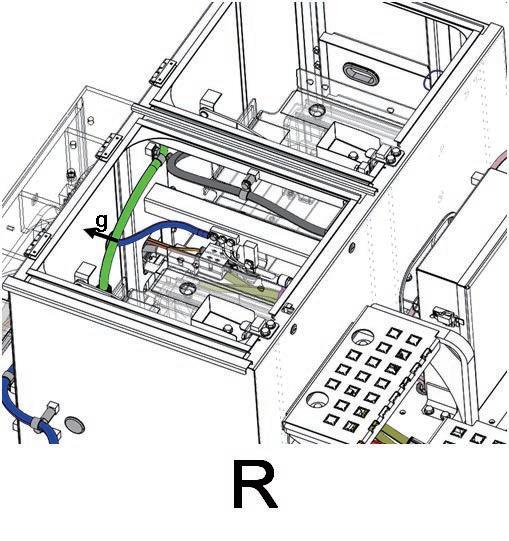


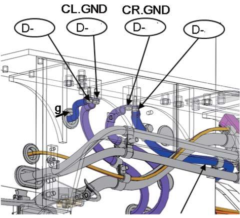
112 a This page is for jump start installed specification only. Assembly procedure Connection of power module assembly wiring (4/4)A-31 Precautions Tools required Equipment required Name Q’ty Name Q’ty Others Machine left InstallTightenConnectioncap.together with 2 Machineterminals.frontTo jump start receptacle Jump receptaclestart Spanner 1

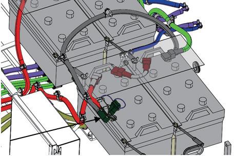

113 Assembly procedure Installation of operator's cab assembly (1/4)A-32 Precautions Tools required Equipment required Take care not to break the mount dowel pin. Name Q’ty Name Q’ty Others Operator's cab assembly No.Part No.Parts nameQ'ty E-1 21T-54-34151-XC Plate1 E-2 01034-81225 Bolt6 When installing cab, remove mount cover and stopper bracket (see next page). 1 2 Socket 19 mm in width across flats 1 Extension L200 1 Air impact wrench 1
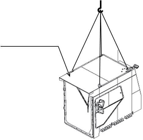
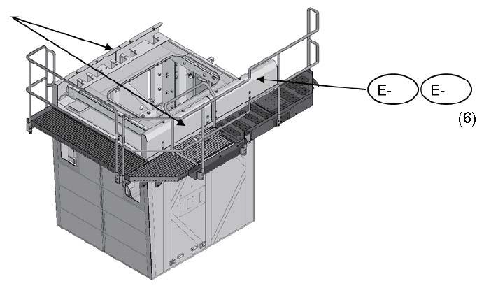
114 Assembly procedure Installation of operator's cab assembly (2/4)A-32 Precautions Tools required Equipment required Take care not to break the mount dowel pin. Name Q’ty Name Q’ty Others When riding in cab ,adjust with shims so that clearance to be 1.5 to 3 mm. Cab assembly STD. Quantites of Shim PortionPart NumberQuantitiesPart M21T-54-366903K21T-54-36690121T-54-366801J21T-54-36690121T-54-366801NumberQuantitiesL21T-54-36690121T-54-366801N21T-54-36690221T-54-366801P21T-54-36690221T-54-366801 No.Part No.Parts nameQ'ty E-3 21T-54-37980Bracket6 t1.6 E-4 21T-54-36680Plate9 t3.2 E-5 21T-54-36690Plate12 E-6 01024-81030Bolt12 E-7 21T-54-37990Cushion6 Left of machine Front of machine 76534 E4 E5 Z Socket 17 mm in width across flats 1 Extension L200 1 Air impact wrench 1 E3 E7 E-6
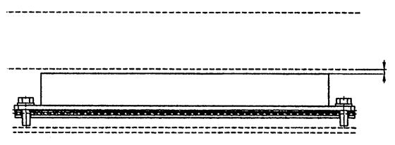
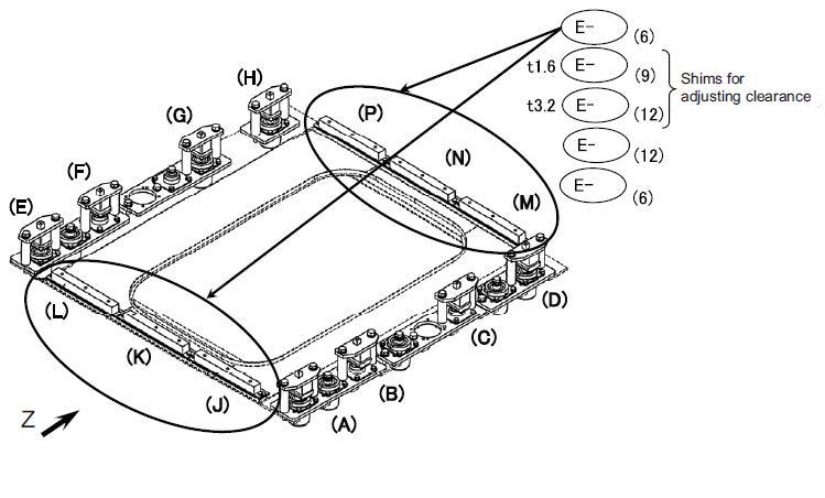
115 Assembly procedure Installation of operator's cab assembly (3/4)A-32 Precautions Tools required Equipment required Take care not to break the mount dowel pin. Name Q’ty Name Q’ty130Others – 150 mmCab assembly DowelMountpin No.Part No.Parts nameQ'ty E-8 21T-54-35312-NK Bracket8 E-9 8230-46-1130Bolt16 E-10 01643-32060Washer16 1)Remove all the stopper brackets installed to the mount. 2)Lower the cab assembly to 130 – 150 mm above the mount. 3)Raise each mount assembly. While setting the dowel pin, fix the mount temporarily with the bolt at its center. E8 E9E10 (16) Socket 30 mm in width across flats 1 Extension L200 1 Air impact wrench 1
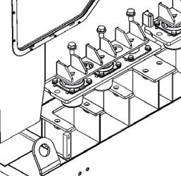
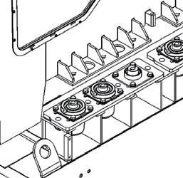
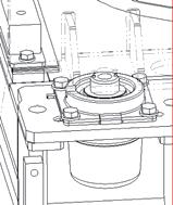
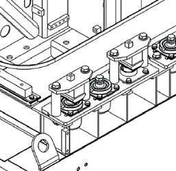
116 Assembly procedure Installation of operator's cab assembly (4/4)A-32 Precautions Tools required Equipment required Take care not to break the mount dowel pin. Name Q’ty Name Q’ty Others (M20 × 1.5) •Delivered individually with pin assembly for installation to viscous-mount-less portion. Mounting section (A) – (H) 4)After installing all the mounts temporarily, lower the cab assembly and tighten the bolt at the center of each mount. 5)While adjusting the clearance at the stopper, install the stopper brackets again. (M20 × 2.5) Adjust so that clearance will be 1.5 – 3 mm when operator sits in cab seat. Standard quantity of shim Section Standard cabCab with front GD12C11BA11t3.2t1.6t3.2t1.6guardE1FH11 No.Part No.Parts nameQ'ty t1.6 Shim E-11 21T-54-36661Plate16 t3.2 Shim E-12 21T-54-36671Plate8 E-13 21T-54-35321Cushion8 E-14 21T-54-35732Pin4 E-15 04020-00514 Cotter pin 8 E-16 01050-52040Bolt4 E 17 01643-32060Washer4 E-16E-15E-14E-17 E-11 E-12E-13 (8) Socket 30 mm in width across flats 1 Extension L200 1 Air impact wrench 1
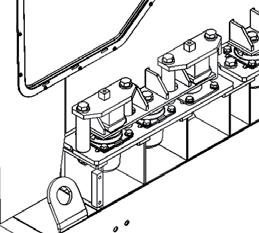
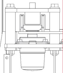
117 Assembly procedure Installation of rotary lamp (if equipped) (1/2)A-33 Precautions Tools required Equipment required Precautions to be observed when connecting DT, DTP or DTHD connector • After connecting the connector, check visually that the connector is locked securely. If the connector is not locked securely, reconnect it. Name Q’ty Name Q’ty Others When locked When unlocked No.Part No.Parts nameQ'ty E-18 8295-06-1480Lamp1 E-19 21T-06-17430-XCBracket1 E-20 01024-81225Bolt2LeftofmachineFrontofmachine 18 1920 Socket 19 mm in width across flats 1 Extension L200 1 Air impact wrench 1 ★This page is for rotary lamp spec. only. Install lamp(E-18) with nuts which are contained in it, onto bracket (E-19) at first.
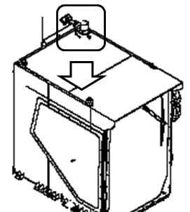

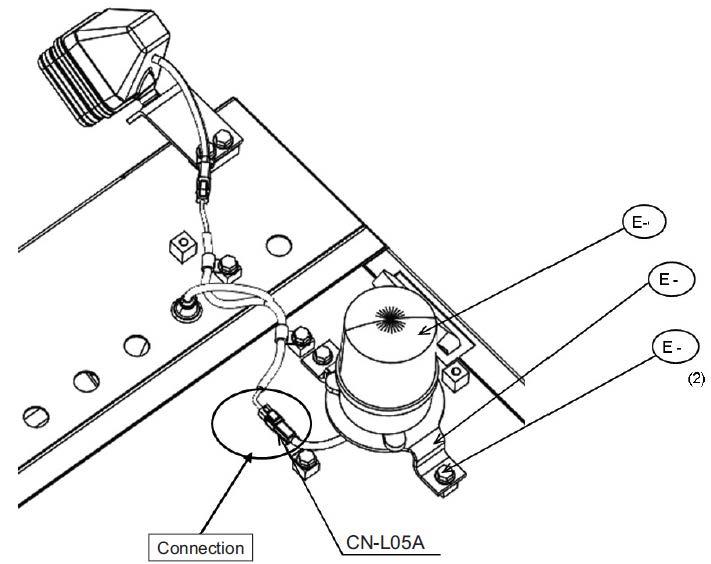
118 Assembly procedure Installation of rotary lamp (if equipped) (2/2)A-33 Precautions Tools required Equipment required Precautions to be observed when connecting DT, DTP or DTHD connector • After connecting the connector, check visually that the connector is locked securely. If the connector is not locked securely, reconnect it. Name Q’ty Name Q’ty Others When locked When unlockedFront of machine Left of machine ★This page is for rotary lamp spec. only. No. Part No. Parts name Q'ty E-21 8295-06-1480 Lamp 1 E-22 21T-06-33610-XC Plate 1 E-23 21T-06-17430-XC Bracket 1 E-24 01024-81225 Bolt 2 E-25 04434-51012 Clip 1 E-26 01024-81220 Bolt 1 21232422 25 26 Socket 19 mm in width across flats 1 Extension L200 1 Air impact wrench 1 Install lamp(E-21) with nuts which are contained in it, onto bracket (E-23) at first.
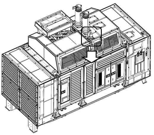


119 Assembly procedure Installation of iridium antennaA-34 Precautions Tools required Equipment required Name Q’ty Name Q’ty Others Left of machine Front of machine The antenna is installed to the operator's cab (upper surface). Remove the bolt, and raise the antenna to install as indicated below. Take care of the antenna cable not to break. Socket 19 mm in width across flats 1 Extension L200 1 Air impact wrench 1
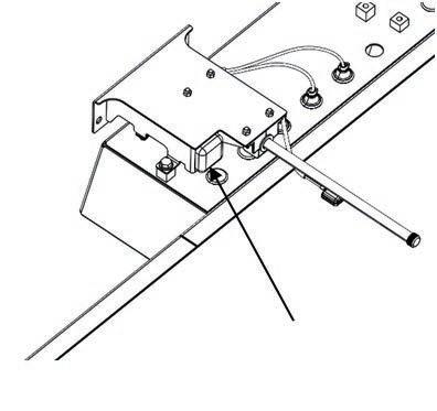
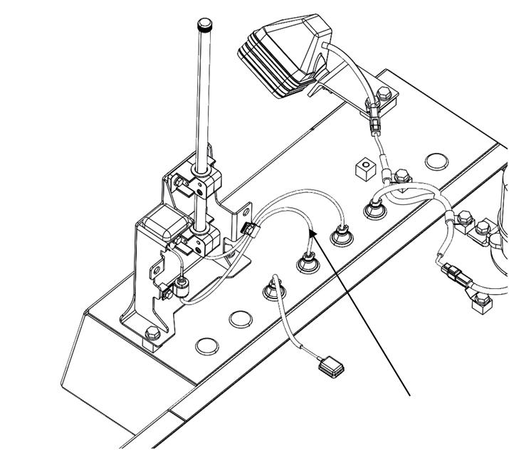
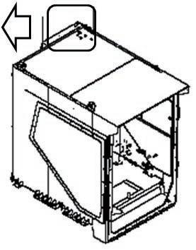


120 Assembly procedure Connection of operator's cab assembly wiring (1/3)A-35 Precautions Tools required Equipment required Precautions to be observed when connecting DT, DTP or DTHD connector • After connecting the connector, check visually that the connector is locked securely. If the connector is not locked securely, reconnect it. Name Q’ty Name Q’ty Others When locked When unlocked Front of machine Left of machineNo.Part No.Parts nameQ'ty E-27 01024-81020Bolt1 Socket 17 mm in width across flats 1 Extension L200 1 Air impact wrench 1 Lower rear of cab 27 Z Z Cab base ceiling CN-A95CN-A01 CN-A71 For DisconnectKomVisionthisclip temporary to connect the connector easily.
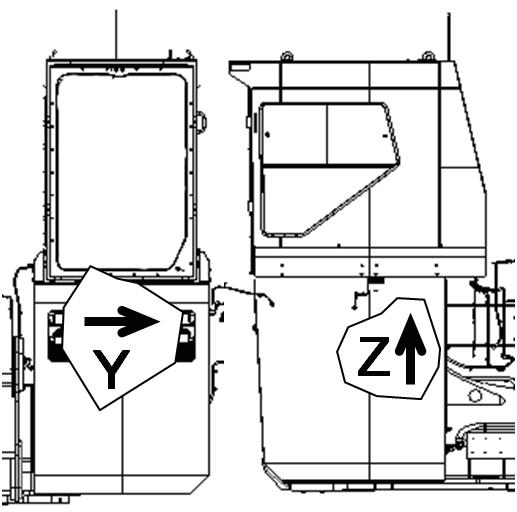
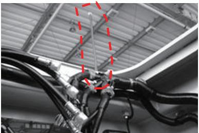


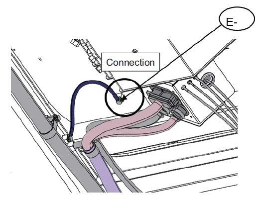
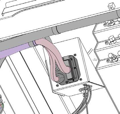
121 Assembly procedure Connection of operator's cab assembly wiring (2/3)A-35 Precautions Tools required Equipment required Name Q’ty Name Q’ty GPSIridiumWIFI Y No.Part No.Parts nameQ'ty E-28 207-62-62770-NKBracket1 E-29 01024-81225Bolt2 E-30 04434-53212Clip1 E-31 01024-81225Bolt2 E-32 04434-51712 Clip2 E-33 01024-81225Bolt1 E-34 04434-53212Clip1 E-35 08034-20519Band2KOMTRAXPlusdownloadconnectorConnect GPS cables of cab side and cab base side.Right inner side cab base (inside of power supply board) 28 29 30 31 32 After connection of connector, unify the remaining cables with cable tie. 33 34 35 Socket 19mm in width across flats 1 Extension L200 1 Air impact wrench 1
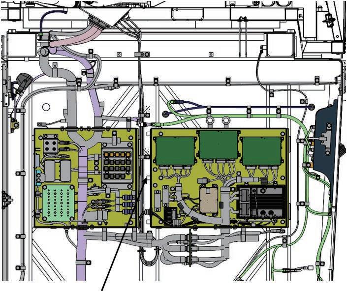

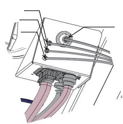
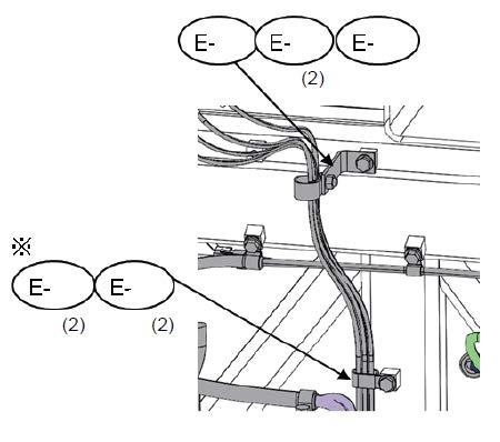
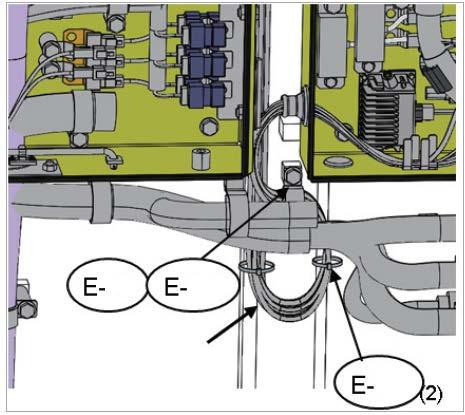
122 Assembly procedure Connection of operator's cab assembly wiring (3/3)A-35 Precautions Tools required Equipment required Name Q’ty Name Q’ty Others GPS WIFI CN5 Iridium Using clips (3 places), unify the cable orderly. KOMTRAX Plus download connector Match with CN4 to N12
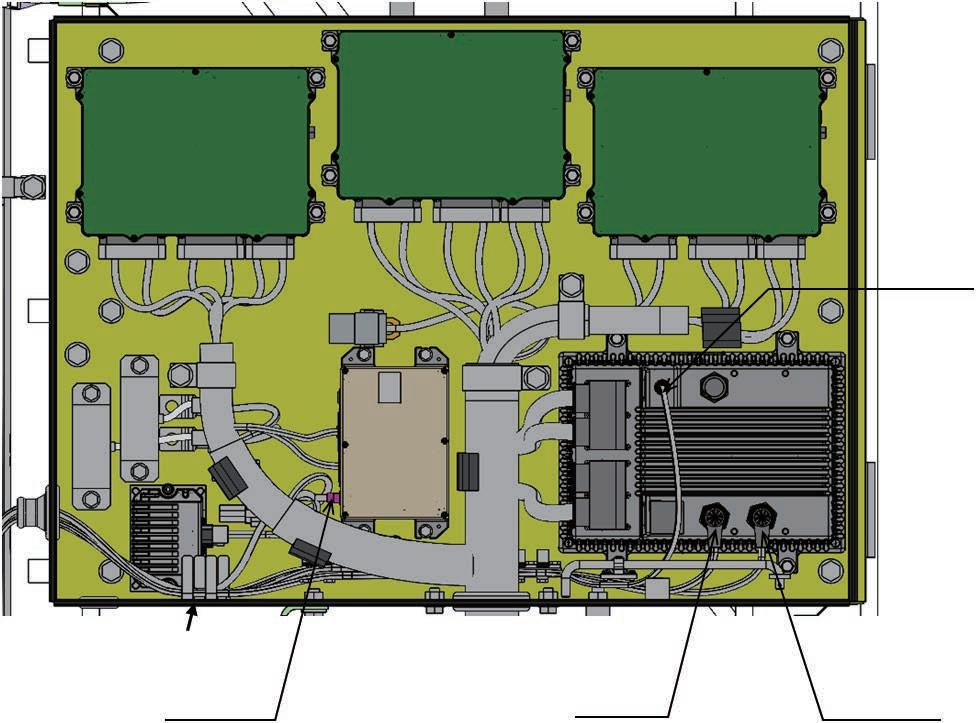
123 Assembly procedure Connection of operator's cab assembly hydraulic piping (1/2)A-36 Precautions Tools required Equipment required Name Q’ty Name Q’ty Others
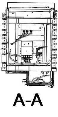
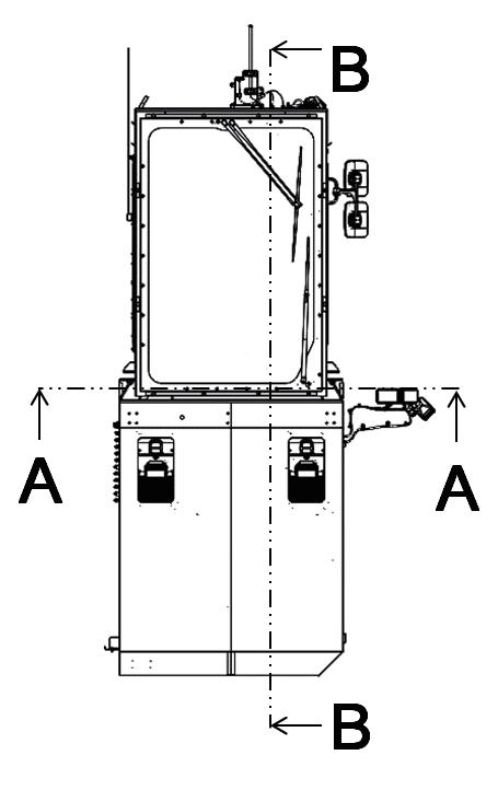
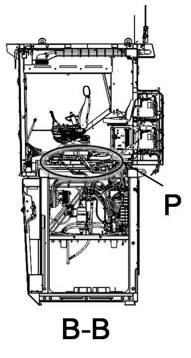
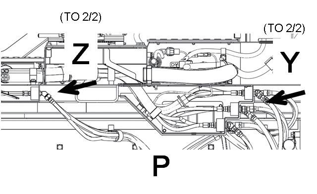
124 Assembly procedure Connection of operator's cab assembly hydraulic piping (2/2)A-36 Precautions Tools requiredEquipment NameQ’tyNameQ’tyrequired Others Disconnection of quick coupler (1) Push the hose adapter into the adapter. (2) Push the cap into the adapter. (3) Pull the hose straight. Hose adapter Hose Adapter (Plug or joint)CapAdapter (Plug or joint) Connection of quick coupler (4) Hold the hose adapter and push it straight into the adapter until it clicks. After connecting the hose, pull its adapter lightly to check that it will not come off. Connection (Quick coupler) Green/Black BlueRed/Black Black/Black Red Blue/Black/Red No. Part No. Parts name Q'ty E-37 02896-61012 O-ring 10 E-38 02896-61009 O-ring 2 38 37 Spanner 1
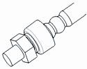
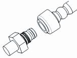
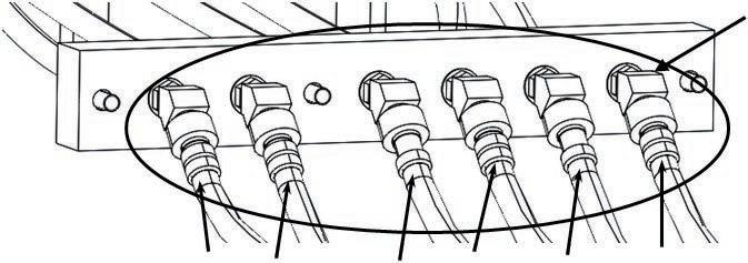

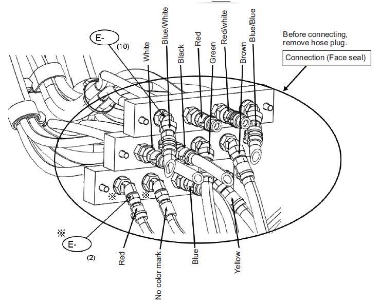

125 Assembly procedure Connection of operator's cab assembly window washer hoseA-37 Precautions Tools required Equipment required Name Q’ty Name Q’ty Others Connection Inside right of cab base Upper washer hoseLower washer hose Tanks A and B may be connected to either of upper and lower washer hoses. P P
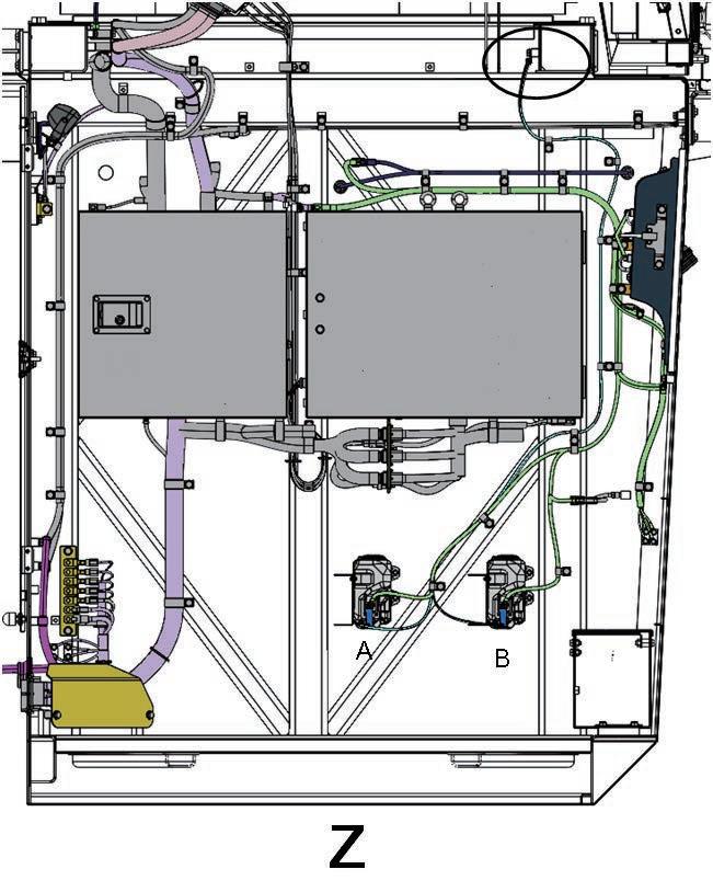
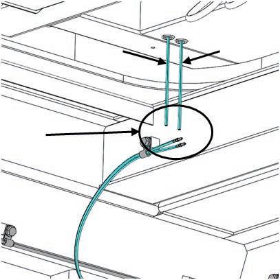

126 Assembly procedure Connection of operator's cab assembly air conditioner piping (1/2)A-38 Precautions Tools required Equipment required 1.To prevent moisture and foreign matter from entering the air conditioner piping, ・ Do not perform this work on a rainy day. Always remove each blind plug just before piping work and perform the work quickly. ・ Never work with cotton work gloves on. 2.Apply compressor oil to the O-rings. ・ Be sure to use compressor oil for refrigerant R134a. ・ Never use oil or grease for other refrigerants. 3.Before connecting, check that the contact surfaces of the O-rings are free from dirt etc. 4.Using two spanners, tighten to the specified torque. (to prevent the damage of piping) Name Q’ty Name Q’ty Others After charging with refrigerant, check for its leakage and wind seal (adhesive) around adapter After charging with refrigerant, check for its leakage and wind seal (adhesive) aroundNo.Partadapter No.Parts nameQ'ty E-39 21T-979-4421Seal4 E-40 21N-979-8160Oil compressor 1 39 39 Spanner 2 40 TightenOil Seal Seal

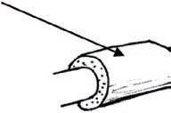
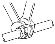

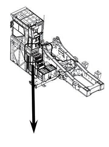
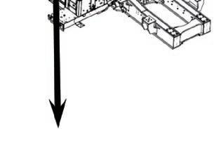
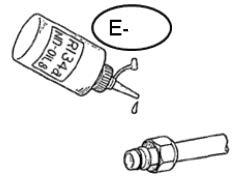
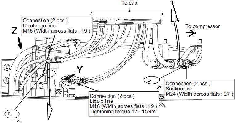
127 Assembly procedure Connection of operator's cab assembly air conditioner piping (2/2)A-38 Precautions Tools required Equipment required Name Q’ty Name Q’ty Others No.Part No.Parts nameQ'ty E-41 21N-62-52670Bracket 1 E-42 01024-81225Bolt4 E-43 04434-51612Clip1 E-44 04435-51412Clip1 E-45 21T-979-4620Bracket 1 E-46 01024-81230Bolt2 E-47 22U-03-31760Clip1 E-48 04434-52212Clip1 41 43 47 45 48 46 42 4442 42 Socket 19mm in width across flats 1 Extension L200 1 Air impact wrench 1 X X
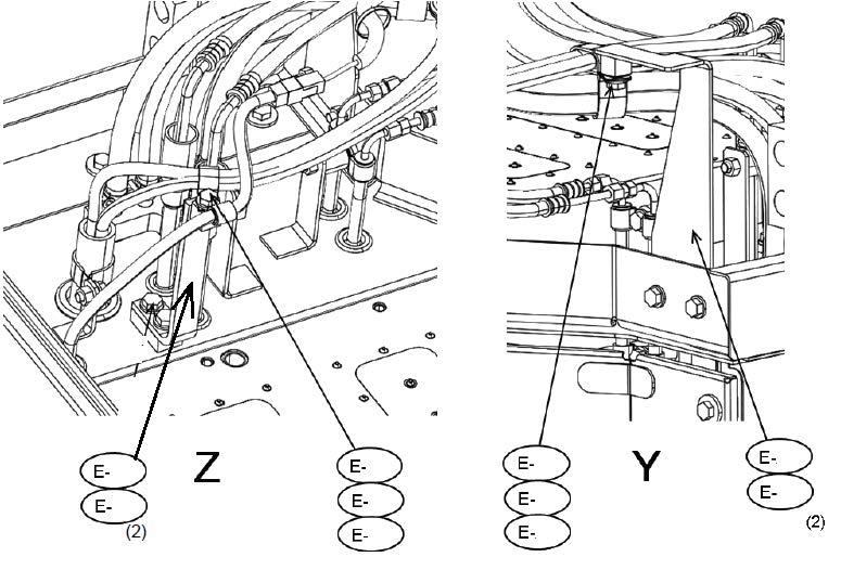
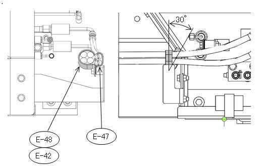
128 Assembly procedure Connection of operator's cab assembly heater pipingA-39 Precautions Tools required Equipment required Name Q’ty Name Q’ty Others C B Rear of cab seen from below White tapeRed tape Insert coolant drain hoses (2 pcs). Connection (4 pcs.) No.Part No.Parts nameQ'ty E-49 07281-00259Clamp4 E-49 Z Z Socket 17 mm in width across flats 1 Extension L200 1 Air impact wrench 1

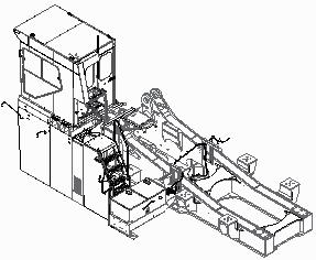

129 Assembly procedure Installation of operator's cab rear floor assemblyA-40 Precautions Tools required Equipment required After the work, reinstall the foot barrier mounting bolts removed to install the eyebolts. Name Q’ty Name Q’ty Left of machine Front of No.PartmachineNo.Parts nameQ'ty E-50 01024-81225Bolt14 Socket 19 mm in width across flats 1 Extension L200 1 Air impact wrench 1 (14) E-50 [ Portion "P" and "Q" ] Use parts installed when transported , for installation of air conditioner hoses and sensor wire


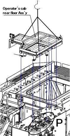
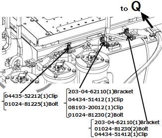

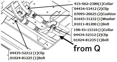
130 Assembly procedure Installation of handrail around operator's cabA-41 Precautions Tools required Equipment required Name Q’ty Name Q’ty Others No.Part No.Parts nameQ'ty E-51 21T-54-41761-XCHandrail1 E-52 01024-81240Bolt,sems12 E-53 198-54-79161-XCBracket1 E-54 01034-81225Bolt4 51 52 52 53 54 Socket 19 mm in width across flats 1 Extension L200 1 Air impact wrench 1

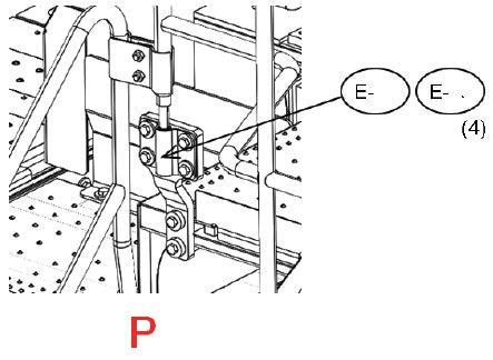
131 Assembly procedure Installation of track frame ladderA-42 Precautions Tools required Equipment required Perform this step after adjusting the track tension to avoid interference with the track. Name Q’ty Name Q’ty Others No.Part No.Parts F-501643-32460Washer16F-401010-82450Bolt8F-301010-82460Bolt8F-221T-30-32241-XCLadder2F-121T-30-32231-XCLadder2nameQ'ty Socket 36 mm in width across flats 1 Extension L200 1 Air impact wrench 1
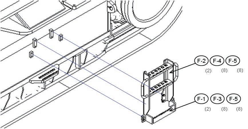
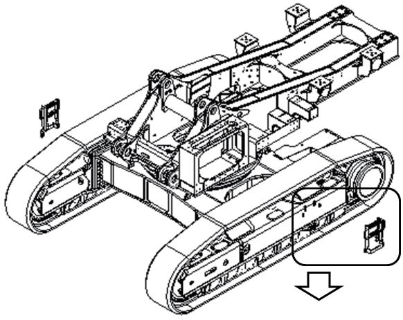
132 Assembly procedure Installation of power module side catwalk assemblies (right and left)A-43 Precautions Tools required Equipment required Name Q’ty Name Q’ty Others Front of machine Left of machine Power module side catwalk assembly Right bracketWithoutassembly:wiringharnessonunderside Left Withassembly:wiringharness bracket on underside Shim(F-7)t1.2 b=220mma=70mm No.Part No. Parts nameQ'ty F-601034-81240 Bolt F-721T-53-32290-SAShim1216Afterinstallingexteriorparts,adjusttheirleveldifferencewiththeseshims.(SeeA-47.) Socket 19 mm in width across flats 1 Extension L200 1 Air impact wrench 1
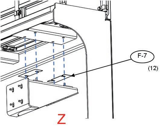
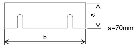
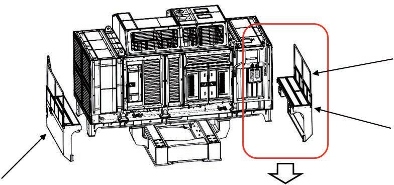


133 Assembly procedure Installation of right floor assembly, grease can cover assembly and center floor (1/2)A-44 Precautions Tools required Equipment required Name Q’ty Name Q’ty Others When slinging the grease can cover assembly,open thetop coverand use thehangingholesin it. Left of machine Front of machine Right floor assembly FrLefo Grease can cover assembly No.Part No.Parts F-1401034-81250Bolt,sems4F-1321T-54-33331-NKStep1F-1221T-53-31560-NKPlate1F-1001643-32060Washer20F-901010-82060Bolt8F-801010-82080Bolt12nameQ'tyF-1121T-53-31550-NKPlate1 Socket 19 mm in width across flats 1 Extension L200 1 Air impact wrench 1 Socket 30 mm in width across flats 1
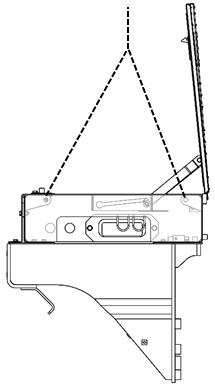
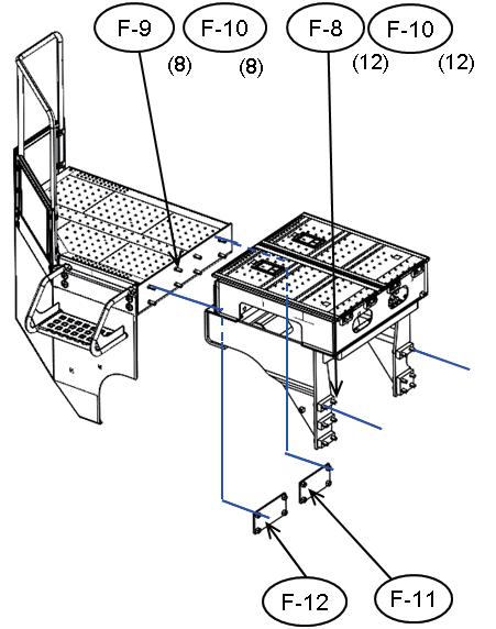
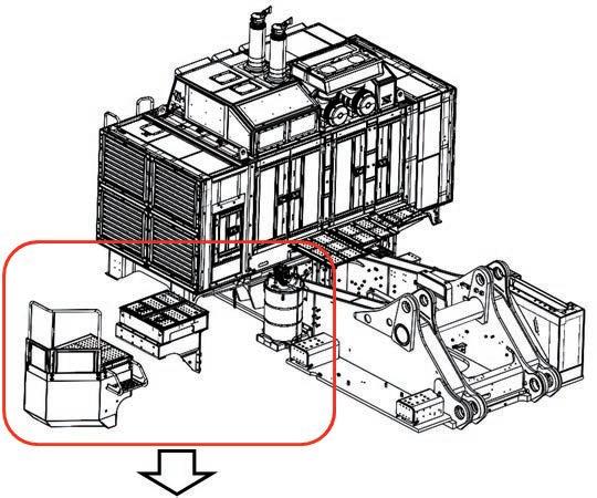
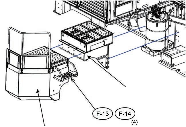


134 Assembly procedure Installation of right floor assembly, grease can cover assembly and center floor (2/2)A-44 Precautions Tools required Equipment required Name Q’ty Name Q’ty Others No.Part No.Parts F-16F-1521T-54-33731-NKCover1nameQ'ty 21T-54-33781-NK Cover1 F-17 21T-54-33791-NK F-2001034-81285Bolt4F-1901034-81230Bolt,sems16F-1821T-53-31590-NKStep1Cover1 Clearance: 20 ± 5mm Clearance: 10 ± 5mmClearance: 10 ± 5mm Clearance: 17 ± 5mm Clearance: 15 ± 5mm Extension L200 1 Air impact wrench 1 Socket 19 mm in width across flats 1
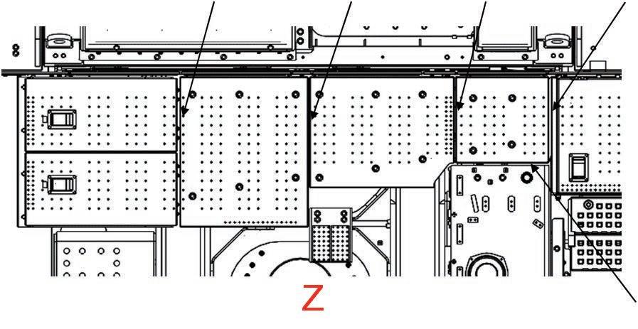
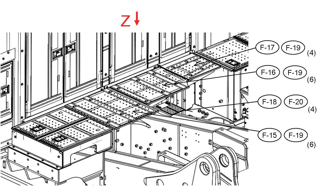
135 Assembly procedure Installation of fuel tank right catwalk assemblyA-45 Precautions Tools required Equipment required Name Q’ty Name Q’ty Others Left of machine Front of machine Fuel tank right catwalk assembly No.Part No.Parts F-2101034-81240Bolt16nameQ'ty Extension L200 1 Air impact wrench 1 Socket 19 mm in width across flats 1
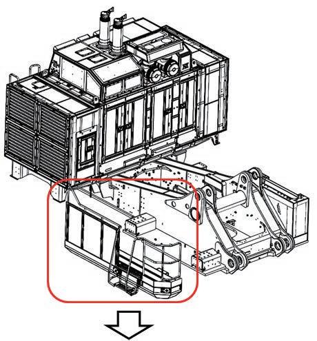


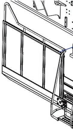
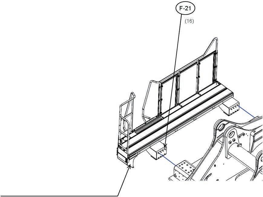

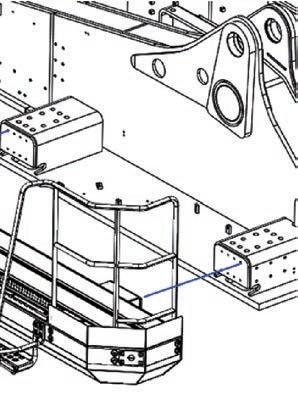
136 Assembly procedure Installation of fuel tank front catwalk assemblyA-46 Precautions Tools required Equipment required Name Q’ty Name Q’ty Others Left of machine Front of machine Fuel tank front catwalkNo.Partassembly No.Parts F-2201034-81250Bolt,sems6nameQ'ty Extension L200 1 Air impact wrench 1 Socket 19 mm in width across flats 1
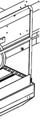
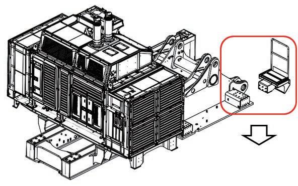


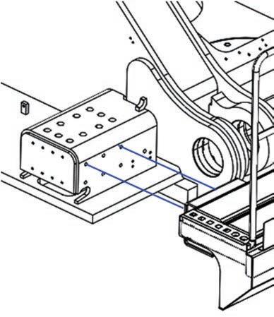
137 When and after assembling the exterior parts, adjust each clearance as shown below. Adjust the clearance finally after installing the counterweight. Reduce the level difference between the outside surfaces of adjacent exterior covers to 5 mm or less. Reduce the level difference between the underside surfaces of adjacent exterior covers to 7 mm or less. Assembly procedure Adjustment of exterior parts clearanceA-47 Clearance: 20 ± 5 mm Clearance: 20 ± 5 mm Clearance: 15 ± 5 mm Clearance: 15 ± 5 mm Clearance: Max. 30 mm Clearance: 15 ± 5 mm Clearance: 15 ± 10 mmance: ± 5 mm mm Clearance: 20 ± 5 mm


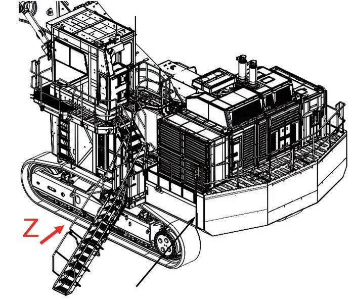


138 Assembly procedure Connection of grease reel pipingA-48 Precautions Tools required Equipment required Name Q’ty Name Q’ty Others Left of machine Front of machine Connection Connection Spanner 1
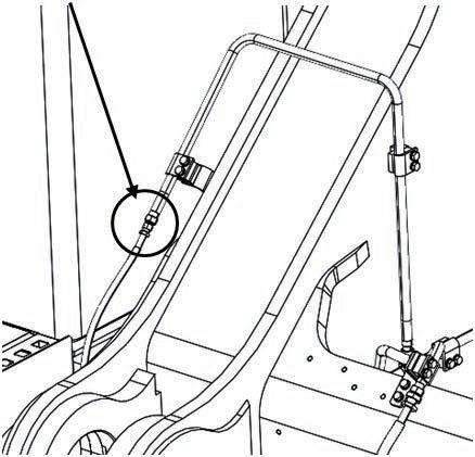
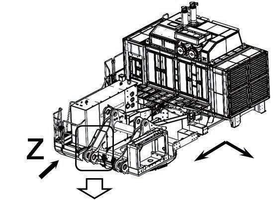
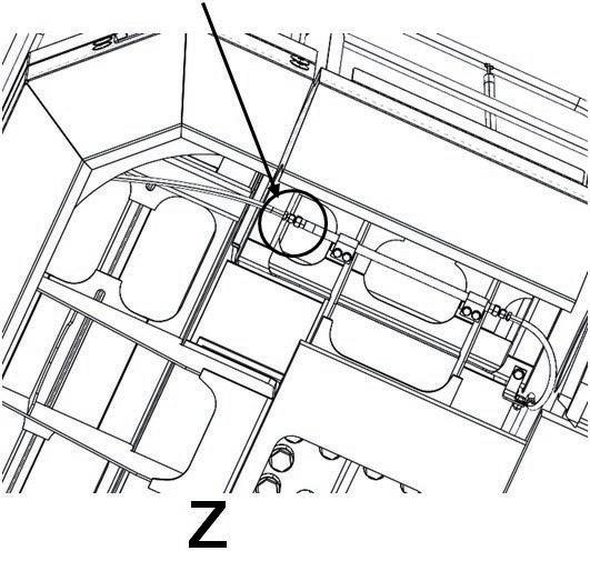
139 The ladder unit is installed to the left deck assembly when transported. Install the left deck assembly to the machine and hang the ladder and then install the parts in the following figure. Assembly procedure Installation of access ladder assemblyA-49 Precautions Tools required Equipment required Name Q’ty Name Q’ty Others No.Part No.Parts F-2501034-81230Bolt,sems6F-2401034-81230Bolt,sems4F-2321T-54-41620-XCStep1nameQ'ty Access lader assembly Extension L200 1 Air impact wrench 1 Socket 19 mm in width across flats 1
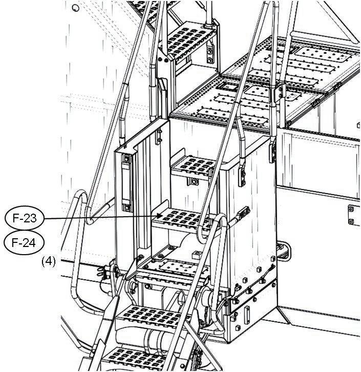
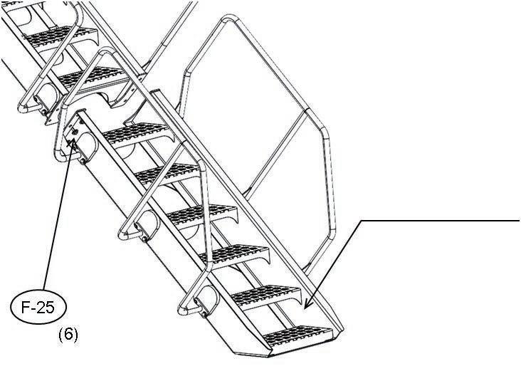
140 Assembly procedure Installation of counterweight assemblyA-50 Precautions Tools required Equipment required Tighten the counterweight mounting bolts permanently after tightening all the bolts (Preventiontemporarily. of seizure of the bolts) Name Q’ty Name Q’ty Tap (M42 × 3) 1CounterweightOthers assembly 24,800 kg M42 × 3, L = 670 mm, Width across flats 65 mm 3 Tightening torque : 3430 -- 4212 Nm {350 -- 430 kgm} 4 bolts and 4 washers are used to install transportation jigs during transportation. No.Part No.Parts F-28209-46-11210F-2721T-46-34120Bolt12nameQ'ty Washer F-3101024-81225Bolt12F-3021T-46-34131-NKCover2F-2921T-46-34141-NKCover212 Air impact wrench 1 Socket 19 mm in width across flats 1 Socket 65 mm in width across flats 1 16 time wrench 1
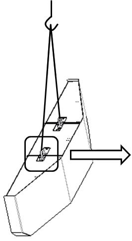
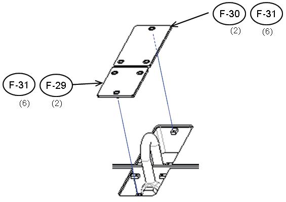
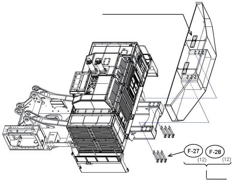
141 Assembly procedure Installation of deformation preventing stoppers for catwalk assemblies (left and right) on the side of power moduleA-51 Precautions Tools required Equipment required After adjusting the clearances of exterior parts in (A-47), adjust the clearance of the stopper. (2 places on the right and left sides) Name Q’ty Name Q’ty Others shim (F-33) t 4.5 No.Part No.Parts nameQ'ty F-32 21T-53-33640-NKBracket2 F-33 21T-53-33650-NKShim4 F-34 01024-81255Bolt,sems4 Air impact wrench 1 Socket 19 mm in width across flats 1 33 32 34 P P
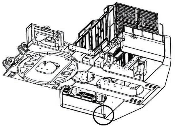
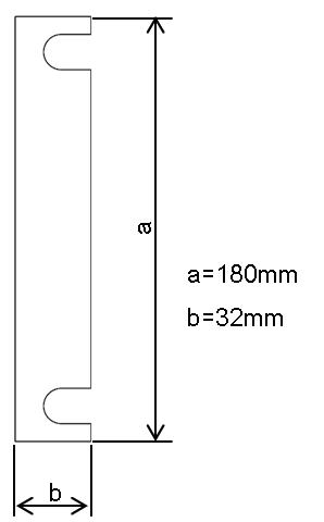
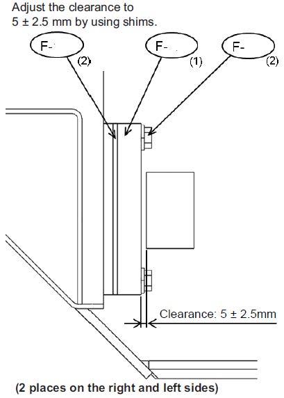
142 Assembly procedure Installation of handrail on counterweightA-52 Precautions Tools required Equipment required Name Q’ty Name Q’ty Others No.Part No.Parts nameQ'ty F-35 21T-54-42570-XCHandrail1 F-36 21T-54-42560-XCHandrail1 F-37 01024-81250Bolt,sems16 37 36 37 35 Air impact wrench 1 Socket 19 mm in width across flats 1
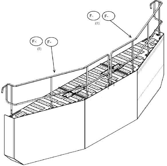
143 Assembly procedure Installation of handrail clamps (1/3)A-53 Precautions Tools required Equipment required Name Q’ty Name Q’ty Others 8 places marked with (Portion P, Q, S) No.Part No.Parts nameQ'ty F-38 21T-54-32911-XCClamp10 F-39 21T-54-32921-XCClamp10 F-40 01010-81250Bolt20 F-41 175-54-34170Washer20 Air impact wrench 1 Socket 19 mm in width across flats 1 Extention L200 1 41 40 39 38
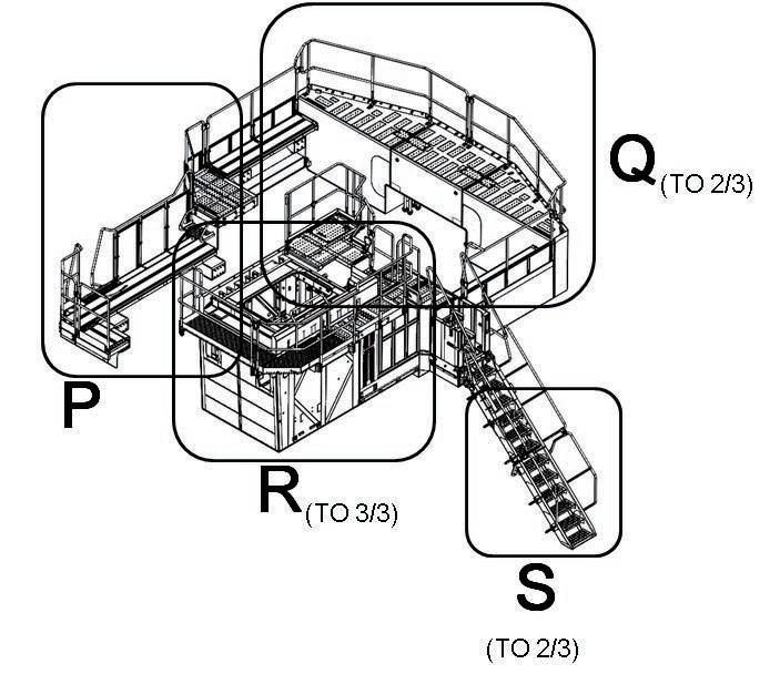


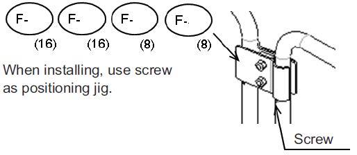
144 Assembly procedure Installation of handrail clamps (2/3)A-53 Precautions Tools required Equipment required Name Q’ty Name Q’ty Others 2 places marked with A Z Air impact wrench 1 Socket 19 mm in width across flats 1 Extention L200 1 41 40 39 38
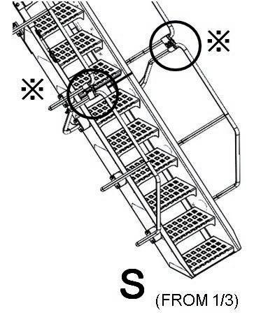
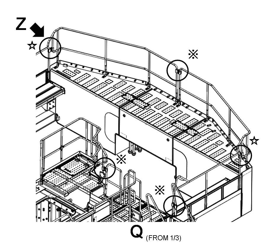
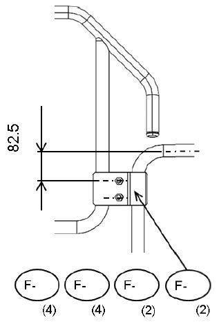
145 Assembly procedure Installation of handrail clamps (3/3)A-53 Precautions Tools required Equipment required Name Q’ty Name Q’ty Others When installing, use screw as positioning Wheninstalling,usescrewjig. No.Part No.Parts nameQ'ty F-42 21T-54-31140-XCClamp1 F-43 21T-54-31150-XCClamp1 F-44 01034-81245Bolt2 (Clamp is temporaly installed to front catwalk) Air impact wrench 1 Socket 19 mm in width across flats 1 Extention L200 1 T T E-42 E-43 E-44 (2)

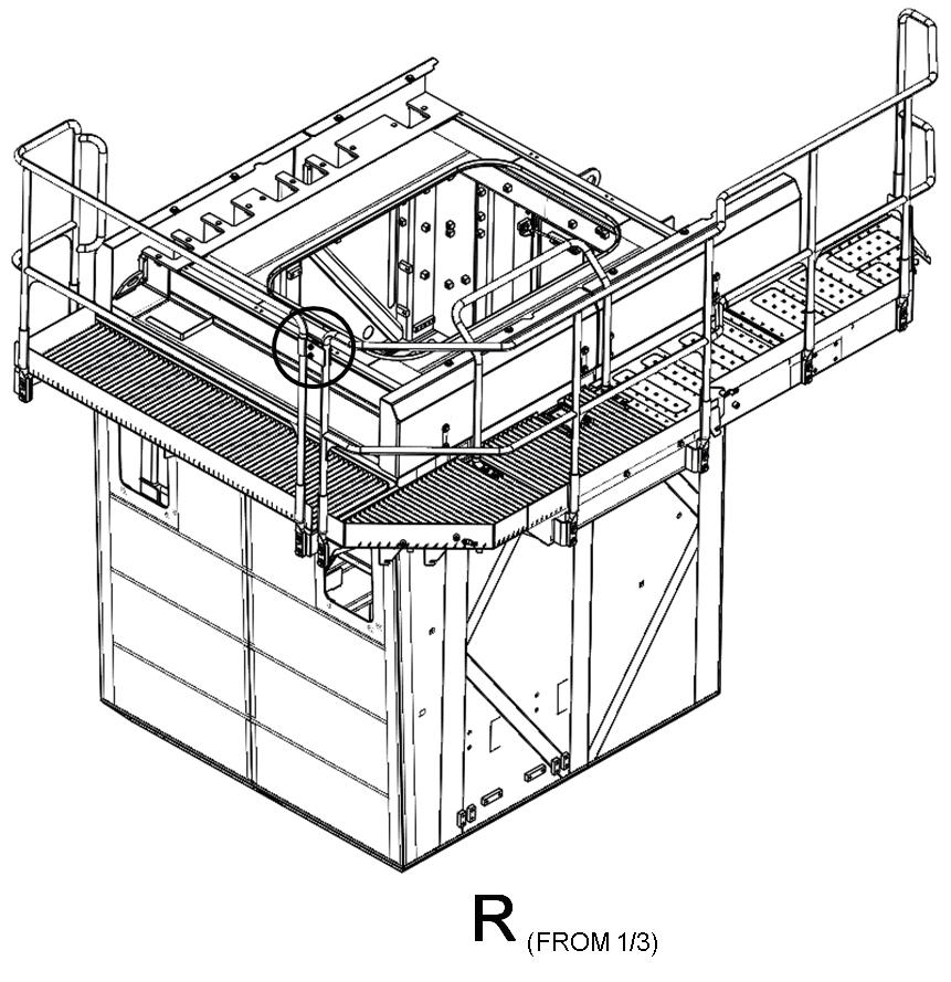

146 Assembly procedure Connection of fuel cut wireA-54 Tools required Equipment required Name Q’ty Name Q’ty Others (1)Remove<Procedure>the cotter pin of the fuel cut wire connecting pin and then remove the wire. (2)Pass the wire through the hole of the step and connect it to the pin again. Reuse the cotter pin.No.Part No.Parts nameQ'ty F-45 21T-54-37220Chain1 F-46 04530-10815Eye bolt1 F-47 21T-04-32180Wire rope1 Fuel cut wire P Q R R P Q (1) F-47 Step Fuel cut wireChain


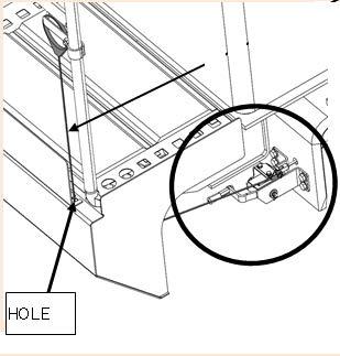
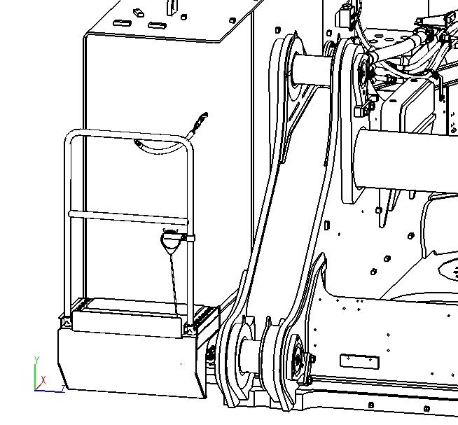
147 Assembly procedure Connection of drain piping under power moduleA-55 Precautions Tools required Equipment required Name Q’ty Name Q’ty Others Underside of revolving frame Project the ends of engine breather pipe and muffler drain pipe 10 mm from the underside of the revolving frame. Note nderside1 evolving frame Left of FrontmachineofmachinePTOoil Engine oil ne No.Part No.Parts nameQ'ty F-4707281-00419 Clamp 2 F-4807281-00259 Clamp 1 Install engine oil hose using clips installed to the evolving frame. (3 places marked with a) Revolving frame left inner surface Air impact wrench 1 Socket 7 mm in width across flats 1 Extention L200 1 4849P 48 Q

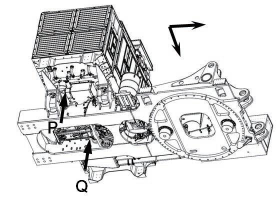
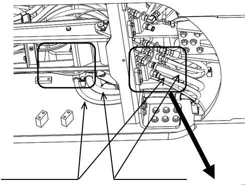

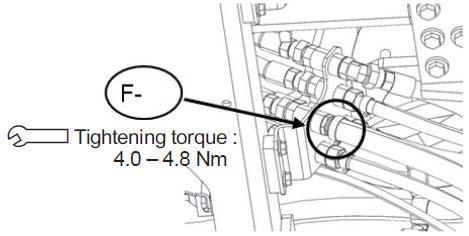


148 Assembly procedure Connection of battery wiringA-56 Precautions Tools required Equipment required Name Q’ty Name Q’ty Others See A-31 Connection of power module assembly wiring
149 Assembly procedure Setting of hydraulic tank strainerA-57 Precautions Tools required Equipment required •Carry out the above work after installing the suction piping and hydraulic pump. •Before starting the engine, check that the strainer is set downward. a Set in normal position (5) when shipped from the factory. NameQ’tyNameQ’ty Others Remove the suction pipe blind plug in the hydraulic tank and set the strainer. Door cover Strainer assembly (2) Flange assembly (2) (1)Open the hydraulic tank upper door cover. (4)Pull up the strainer assembly. (5)Reverse the strainer assembly and insert it in the hydraulic tank again. (6)Install the flange assembly and close the door cover. (2)Remove the flange assembly. (3)(After removal) Air impact wrench 1 Extention L200 1 Socket 19 mm in width across flats 1
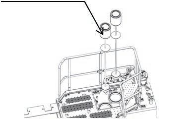
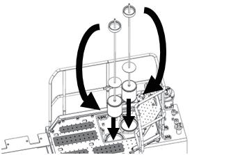

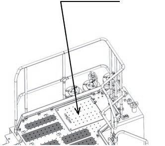
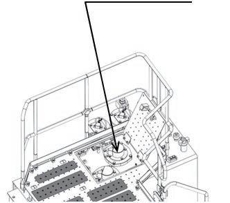
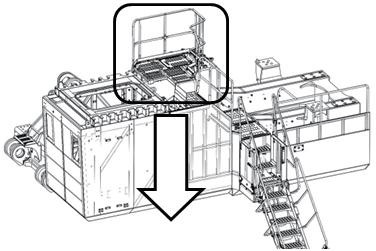
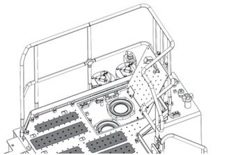
150 1.Inspection and addition of each oil and coolant --- See the M1 for each item. • Inspection and addition of coolant • Inspection and addition of oil in engine oil pan • Inspection of fuel • Inspection and addition of oil in hydraulic tank • Inspection and addition of oil in PTO case • Inspection and addition of oil in swing machinery case • Inspection and addition of oil in final drive case 2.Check for oil leakage Perform air bleeding indicated in the follwing pages. 3.Bleeding air from fuel circuit 1)Fill the fuel tank with fuel (to the FULL level of the fuel level gauge). 2) Check that fuel shut-off lever (1) is pushed down Assembly procedure Starting engine, checking oil and coolant levels, bleeding air from each part, and adjusting track (1/15)A-58 3)
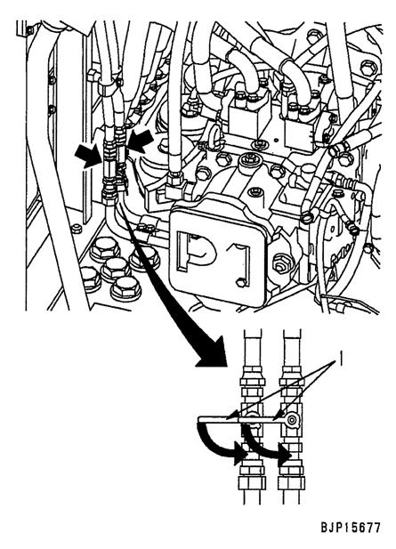
151 Assembly procedure
Starting engine, checking oil and coolant levels, bleeding air from each part, and adjusting track (2/15)A-58 8.10.Before starting the engine, see "Starting engine, checking oil and coolant levels, bleeding air from each part, and adjusting track (3/15)". Then, perform steps 1) to 5) in step 11 (1). 9. Start the engine by cranking it with the starting motor.

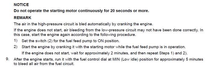


2)Feed hydraulic oil up to the specified level.
4)After bleeders (1) and (2) of the main pumps P1 and P2 stop bleeding air, keep bleeder (1) of main pump P1 loosened, and tighten only bleeder (2) of the main pump P2 temporarily.
Assembly procedure
1)Loosen bleeders (1) – (3) of all hydraulic pump 1 or 2 turns at the same time. a Connect a tube [1] to each bleeder to prevent oil from being scattered and making the machine dirty, and receive the oil in oil pan or others.
a
3)After oil flew out from bleeder (3) of the fan pump PF, tighten bleeder (3) temporarily.
a Even after feeding oil to the hydraulic tank, keep the oil filler cap removed.
5)Loosen plug (5) for suction tube and check that oil flows out. Then, tighten the plug temporarily.
k If air was not bled or air was bled insufficiently, the
Starting engine, checking oil and coolant levels, bleeding air from each part, and adjusting track (3/15)A-58
Air bleeding from each component
152 11.
6)Crank the engine and make sure that oil flows out from bleeder (1) of the main pump P1. Then, tighten the bleeder temporarily.
After removing and installing the hydraulic pump, pump EPC valve and VC valve, or changing hydraulic oil, bleed air from the hydraulic pump according to the following procedures.
(1) Air bleeding from hydraulic pump pump may be broken. So, be sure to bleed air strictly according to the procedures.
a For cranking, idle the engine at low speed for 15 seconds twice.
Note) Bleeding all air takes time.
1)Start the engine and idle it at low speed for about 5
11)Close the oil filler caps of the hydraulic tank.
3 Bleeder : 8.8 – 9.8Nm {0.9 – 1.0kgm}
(2)Air bleeding from work equipment cylinder circuit
12)Keep the engine idling at low speed, raise the work equipment from the ground and swing the upper structure 180°. a After the swing, lower the work equipment completely to the ground.
153
9)Start
14)Loosen the bleeders (1) – (3) of all hydraulic pumps and make sure that bubble-free oil flows out of them. Then, tighten these bleeders temporarily.
15)Keep the engine idling at low speed, raise the work equipment from the ground and swing the upper structure 180°. a Swing the upper structure in the reverse direction from the one in the above Step 12). After the swing, lower the work equipment completely to the ground.
2)Repeatminutes.raising and lowering the boom 4 or 5 times at the low idle. a Stop the piston rod about 100mm before the stroke end and be careful not to relieve it.
3 Plug : 58.8 – 78.4Nm {6 – 8kgm}
10)Loosen the bleeders (1) – (3) of all hydraulic pumps and make sure that bubble-free oil flows out of them. Then, tighten these bleeders temporarily.
a For cranking, idle the engine at low speed for 15 seconds twice. the engine and keep it idle at low speed.
16)Loosen the bleeders (1) – (3) of all hydraulic pumps and make sure that bubble-free oil flows out of them. Then, tighten these bleeders.
7)Loosen the bleeder (2) of the main pump P2. the rear engine and make sure that oil flows out of the bleeder (2) of the main pump P2. Then, tighten the bleeder
17)Stop the engine.
a This work is the same as in the above Step 10).
8)Crank
3)Execute Step 2) at high idle. 4)Bring the piston rod to the stroke end at low idle and relieve 5)Executeit.Steps 2) – 4) for the arm and the bucket. a When the cylinder was replaced, execute the procedures before connecting the work equipment. Especially, when the boom cylinder was installed to the work equipment, the lowering side does not move to the stroke end.
a When removing and installing the work equipment cylinder or when disconnecting and connecting the cylinder circuit piping, bleed air from the work equipment cylinder according to the following procedures. k If air was not bled or air was bled insufficiently, the cylinder piston ring may be broken. So, be sure to bleed air strictly according to the procedures.
Assembly procedure
Starting engine, checking oil and coolant levels, bleeding air from each part, and adjusting track (4/15)A-58
13)Loosen plug (5) for the suction tube and make sure that bubble-free oil flows out of it. Then, tighten the plug.
18)Loosen the oil filler cap of the hydraulic tank slowly and remove it. Relieve pressure from the hydraulic tank and feed hydraulic oil up to the specified level.
Note)temporarily.Bleeding all air takes time.
2)Turn off the swing lock switch.
k If air was not bled or air was bled insufficiently, the travel motor may be damaged. So, be sure to bleed air strictly according to the procedures.
If air was not bled or air was bled insufficiently, the swing motor may be damaged. So, be sure to bleed air strictly according to the procedures.
154
3)Swing the machine while the engine is idling at low speed and make sure that bubble-free oil flows out of bleeder (11). Then, tighten the bleeders.
a When removing and installing the swing motor or when disconnecting and connecting the swing holding brake circuit piping, bleed air from the brake circuit according to the following procedures.
1)Start the engine and loosen bleeder (11).
(5)Air Bleeding from travel motor circuit (Travel motor)
a When removing and installing the travel motor or when disconnecting and connecting the travel motor main circuit pipes, bleed air from the travel motor according to the following procedures.
2)Repeat operations of swing, start, and stop 5 or 6 times.
3 Bleeder : 8.8 – 9.8Nm {0.9 – 1.0kgm} procedure
Starting engine, checking oil and coolant levels, bleeding air from each part, and adjusting track (5/15)A-58
k
If air was not bled or air was bled insufficiently, the swing holding brake may be dragged. So, be sure to bleed air strictly according to the procedures.
k
1)Start the engine and loosen bleeder (12). a The bleeder is mounted on the LH and RH travel
1)Start the engine and operate it while the engine is idling at low speed.
a When removing and installing the swing motor or when disconnecting and connecting the swing motor main circuit pipes, bleed air from the swing motor according to the following procedures.
a The bleeder is mounted on the front and rear swing motors.
2)Makemotors.surethat bubble-free oil flows out of the bleeders (12). Then, tighten the bleeder.
Assembly
(3)Air bleeding from swing motor circuit (Swing motor)
(4)Air bleeding from swing motor circuit (Parking brake circuit)
3 Bleeder : 8.8 – 9.8Nm {0.9 – 1.0kgm} a The swing operation may be as faintly as the swing oil pressure switch turns on.
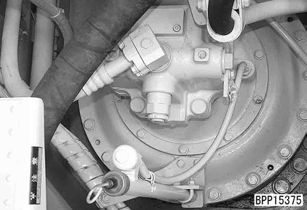
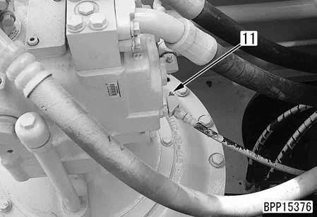
155 (6)Air bleeding from PPC circuit a When removing and installing the control valve or when disconnecting and connecting PPC hose, bleed air from the PPC circuit according to the following procedures. k If air was not bled or air was bled insufficiently, time lag or abnormal sound may occur. So, be sure to bleed air strictly according to the procedures. 1)Start the engine and loosen the bleeder (13). a The bleeders are installed on the elbow of the return spring case of the control valve spool. (28 places in total) 2)Control each actuator while the engine is idle at low speed. 3)Make sure that bubble-free oil flows out of bleeder (13). Then, tighten bleeder. 3 Bleeder : 8.8 – 9.8 Nm {0.9 – 1.0 kgm} k The operation of each lever should be enough to the extent that each hydraulic switch turns on. 4)The circuits and places to be bled are as follows. A :Arm IN circuit (4 places), Q :Boom RAISE circuit (3 places), T :Bucket CURL circuit (4 places), U :Travel REVERSE circuit (4 places), a :Arm OUT circuit (4 places), q :Boom LOWER circuit (2 places), t :Bucket DUMP circuit (3 places), u :Travel FORWARD circuit (4 places) • Front side of control valve • Rear side of control valve Assembly procedure Starting engine, checking oil and coolant levels, bleeding air from each part, and adjusting track (6/15)A-58 Elbow with bleeders


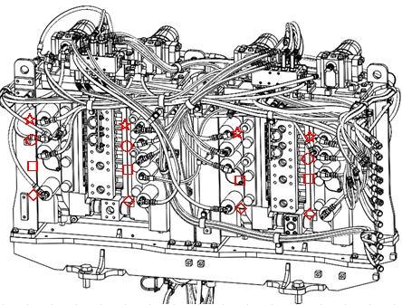
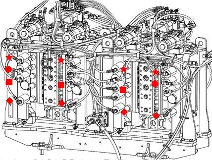
4)While running the engine at low idle, raise the boom and swing the upper structure simultaneously. When oil containing no bubbles flows out of bleeder (2), tighten bleeder (2). Bleeder : 8.8 – 9.8 Nm {0.9 – 1.0 kgm} k Operate each lever slightly to a degree that each oil pressure switch is turned ON. procedure
Bleeder : 8.8 – 9.8 Nm {0.9 – 1.0 kgm} k Operate each lever slightly to a degree that each oil pressure switch is turned ON.
Starting engine, checking oil and coolant levels, bleeding air from each part, and adjusting track (7/15)A-58
(7)Bleeding air from pilot selector valve circuit • Pilot selector valve PV1 • Pilot service valve PV2
3
k If the air bleeding operation is not performed or all air is not bled, the work equipment speed may decrease during compound operation. Therefore, be sure to bleed air according to the specified procedure.
2)While running the engine at low idle, move the arm in and curl or dump the bucket simultaneously. When oil containing no bubbles flows out of bleeder (1), tighten bleeder (1).
156
3)Turn swing lock switch ON.
a If the pilot selector valve circuit was disconnected and connected, bleed air from it according to the following procedure.
3
Assembly
1)Start the engine and loosen bleeders (1) and (2). a Pilot selector valves PV1 and PV2 have 1 bleeder each.
If the hydraulic idler cushion is adjusted defectively, excessive force applies on undercarriage parts and they may break. If the track shoe is to be tensioned right after assembly in the field, follow the procedures below.
No.Part Name Part No. Remarks 4Valve 07959-30000For Grease Cylinder 6Plug 198-30-14420For Cushion Cylinder Section P Section Q Enlarged view of the section P Enlarged view of the section Q
k Idler cushion on PC2000-11 is designed hydraulic. Do not adjust the tension of the track shoe by filling grease into grease cylinder only without adjusting by HIC cylinder.
Filling of oil with pressure into HIC circuit
Starting engine, checking oil and coolant levels, bleeding air from each part, and adjusting track (8/15)A-58
157
Adjusting the tension of track shoe by using grease cylinder (1)HIC system configuration figure HIC cylinder
Assembly procedure
Bleeding air from HIC circuit
12. Air bleeding from HIC (Hydraulic Idler Cushion) circuit, filling of pressurized oil, and adjustment of track shoe tension Hydraulic idler cushions will be abbreviated as HIC.


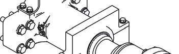

158 HIC Assemblypipingprocedure Starting engine, checking oil and coolant levels, bleeding air from each part, and adjusting track (9/15)A-58 No.Part No. Part Name Remarks 7709-90-74401 Safety valve 821T-60-31510Relief valve with check valve 921T-60-12221 Accumulator 1021T-62-74420 Check valve block 11209-60-52170 Check valve 1221T-60-12251 Drain valve 1321T-60-72120Pressure reducing valve 14209-60-52170 Check valve

159 HIC (Hydraulic Idler Cushion) System 2.Yoke1.Idler (grease cylinder) 3.Plunger (grease cylinder) 4.Plug (for grease) 5.Cushion cylinder (hydraulic cylinder) 5-1Plunger (cushion cylinder) 6.Plug (for cushion cylinder) 7.Safety valve 8.Relief valve with check valve 10.Check9.Accumulatorvalve block 11.Check valve 12.Drain valve (stop valve) 13.Pressure reducing valve 14.Check valve 15.Air bleeding plug 17.Travel16.Plug motor (right) 18.Swivel 21.Main20.Inline19.Controljointvalvefilterpump •Operation
• As the forward circuit of right travel motor is always connected, if the pressure in the circuit is lower than set pressure, 17.7 MPa {180 kg/cm2}, because of gas leak of the accumulator, or if right forward travelling pressure is higher than 17.7 MPa {180 kg/cm2}, hydraulic pressure will be supplied. Therefore, the pressure in the circuit is kept at 17.7 MPa {180 kg/cm2} all the time.
For filling of oil with pressure to hydraulic circuit, it is started to fill oil to forward circuit of right travel motor through check valve (14) and pressure reducing valve (13). By pressure reducing valve (13), the pressure of filled oil is set to 17.7 MPa {180 kg/cm2}, and oil is filled in cushion cylinder (5), so the plunger (5-1) stretches to stroke end. At the same time, oil is filled into accumulator (9) to pressurize the nitrogen pressure gas sealed inside, from 13.2 MPa to 17.7 MPa {135 kg/cm2 to 180 kg/cm2}.
• If the exterior force on the idler is released, the pressure will push the oil reversely, returning the oil to cushion cylinder (5) through the check valve in relief valve with check valve (8). Therefore the inner pressure reduces while idler (1) moves forward, and the system returns to the original condition.
• If there is abnormal high pressure in the circuit when idler (1) withdraws under exterior force because of gas leak in accumulator (9) or abnormality in relief valve with check valve (8), safety valve (7) will be operated to prevent accidents, such as breakage of piping, etc.
• The cracking pressure (opening pressure) of relief valve with check valve is 25.7 MPa {262 kg/cm2} (cracking pressure of relief valve : 8.0 MPa {81.6 kg/cm2} (when back-pressure is 0 MPa {0 kg/cm2}) + back-pressure : 17.7 MPa {180 kg/cm2} = 25.7 MPa {262 kg/cm2}).
• Oil pushed out by plunger (5-1) flows into accumulator (9)after relief valve with check valve (8) opens, and nitrogen gas in the accumulator is pressed, raising the inner pressure.
Assembly procedure Starting engine, checking oil and coolant levels, bleeding air from each part, and adjusting track (10/15)A-58
• Yoke (2) works as grease cylinder, and grease is filled inside plunger (3).
• If idler (1) withdraw under exterior force, plunger (5-1) of cushion cylinder (5) is pushed back and the inner pressure of the cylinder rises. If this pressure rises higher than the cracking pressure of relief valve with check valve (8), this valve will open and the oil will flow into accumulator (9).
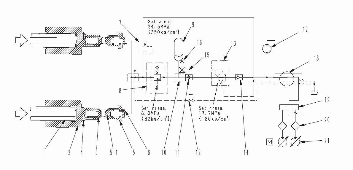
160 (1)Bleeding of air from idler cushion circuit a Be sure to bleed air from idler cushion circuit before grease is filled into grease cylinder. 1)Loosen plug (4) of grease cylinder for one turn . (2 places in left and right sides) 2)Completely open drain valve (12) on the inner side of the center frame. 3)Loosen air bleeding plug (6) of the cushion cylinder about one turn. (2 places in left and right sides) 4)Remove plug (15) on the bottom of check valve block (10), and loosen air bleeding plug (16) on the side for about one turn . 5)Run the engine at low idle for 2 to 3 minutes. 6)Completely close drain valve (12) when clean oil flows out from the holes of air bleeding plug (6) and plug (16). 7)After that, tighten air bleeding plugs (15), (6) (2 places in left and right sides). 8)Tighten plug (16). 9)Tighten plugs (4) (2 places in the right and left sides). 10)Finally, tighten drain valve (12). Assembly procedure Starting engine, checking oil and coolant levels, bleeding air from each part, and adjusting track (11/15)A-58 View Z Rear of the machine No. Tightening torque 4 58.8 – 88.3 Nm {6 – 9 kgm}163.9156 – 6.9 Nm {0.4 – 0.7 kgm}
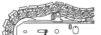
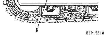
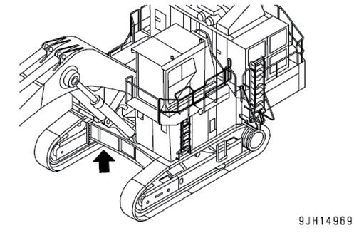
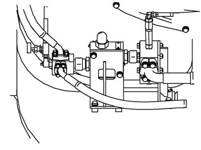

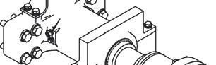

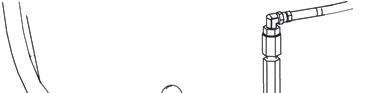
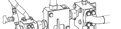

a Even when projecting length (a) of the hydraulic cushion cylinder plunger is within the specified values, occasionally the charging pressure of oil in HIC circuit is low.
Testing
• Protrusion amount (A): 135 ± 5 mm
1.Run the engine at low idle and drive the machine forward by the length of track on ground, and then stop slowly.
3)Confirm that projecting length (a) of the hydraulic cushion cylinder plunger is 135 ± 5mm on both L.H. and R.H. sides.
2)In order to increase the filled oil pressure in HIC circuit, keep the bucket teeth upright and lowered into the ground to prevent the machine from travelling, and obtain a hydraulic relief for 4 to 5 seconds through directional operations of R.H. travel lever. Repeat these operations 5 or 6 times.
2.Place steel bar (b) on the track shoe between 2nd carrier roller (1) and 3rd carrier roller (2).
• Maximum clearance (a): 10 – 30 mm Assembly procedure
3.Measure the maximum clearance between the track shoe top and the steel bar.
(3)Testing and adjusting track shoe tension
Starting engine, checking oil and coolant levels, bleeding air from each part, and adjusting track (12/15)A-58
1)Run the engine at medium speed. a Before working, confirm that drain valve (12) is tightened.
161
a Do not carry out these directional operations on any slippery surface (such as steel plate).
4)If projecting length (a) has not become 135 ± 5mm, carry out the operations in 2) described above once again and be sure to obtain the specified dimension of (a). a In case the length of 135 ± 5mm cannot be obtained, it is supposed that some excessive grease is contained in the grease cylinder. Discharge such excessive grease in accordance with the item "Adjusting grease cylinder" in the next page.
<Check point> If the front edge of hydraulic cushion cylinder plunger is located near the center of the inspection hole on the side face of crawler frame, the projecting length is approximately within the specified values.
(2)Procedure for filling of oil with pressure into HIC circuit
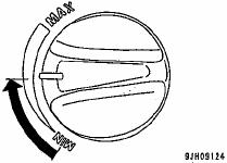
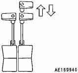
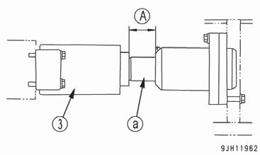
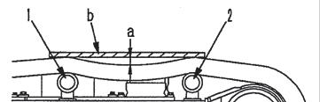
4)Adjust the track shoe tension by adding grease until protrusion amount (B) of grease cylinder (3) becomes 35 to 190 mm (*). If the tension is still not enough, the track shoe may be extremely worn, so it is necessary to reverse or replace pins, bushing pins and bushings.
a (*) The amount is 30 to 45 mm when the machine is delivered from the plant. Starting engine, checking oil and coolant levels, bleeding air from each part, and adjusting track (13/15)A-58
Before injecting grease, confirm that protrusion amount (A) of plunger (a) of hydraulic cushion cylinder (5) is 135 ± 5 mm on both left and right sides. Confirm the protrusion amount of hydraulic cushion cylinder again after injecting grease, and if the amount is not in this range, loosen plug (4) for one turn, eject the grease, and fill oil with pressure again into HIC circuit in accordance with procedure (2).
k
Assembly procedure
1)Inject grease into cylinder through the plug (4) with a grease gun.
k Do not loosen plug (4) for more than one turn. If the plug is loosened for more than one turn , plug (4) may fly out by inside high pressured grease, so parts other than plug (4) should not be loosened. Keep face away from the mounting direction of plug (4).
162
(4)Adjusting grease cylinder Adjust grease cylinder after adjusting hydraulic cushion cylinder.
a
Avoid adjusting the tension of the track shoe by filling grease into grease cylinder without adjusting hydraulic cushion cylinder. Extreme force may apply on the undercarriage, causing breakage.
• When increasing tension Prepare grease pump.
3)Check the track shoe tension again, and if the tension is not proper, adjust it again.
2)To check that the tension is normal, move the machine forward slowly.
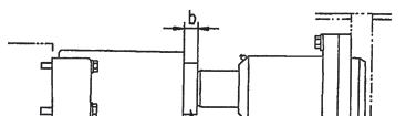
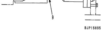
1)Loosen plug (4) gradually to eject the grease.
2)Turn plug (4) a maximum of one turn.
5)To check that the proper tension has been achieved, move the machine backwards and forwards.
2)After completion of releasing the remaining pressure, tighten drain valve (12).
6)Check the track shoe tension again, and if the tension is not proper, adjust it again.
163
• When reducing tension
(5)Procedures for releasing the remaining pressure in HIC circuit
Lower the work equipment completely to the ground, operate the work equipment control lever several times to release the remaining pressure in piping after stopping the engine, and then release the internal pressure of the hydraulic tank by gradually loosening the oil filler cap of the tank.
Assembly procedure
3)If the grease does not come out smoothly, move the machine backwards and forwards a short dis4)Tightentance. plug (4).
1)Loosen drain valve (12) slowly and relieve pressure remaining in the circuit. k If the valve is loosened too fast, high pressure may be generated in the tank circuit, so loosen drain valve (12) slowly. The remaining pressure will be completely released after more than one minute.
If eject grease other than following procedure, it may be great danger. Never fail to forget them.
Starting engine, checking oil and coolant levels, bleeding air from each part, and adjusting track (14/15)A-58 View Z Rear of the machine
HIC circuit is closed circuit filled with highly pressurized oil, so if the HIC devices are removed or piping is disconnected, release the remaining oil pressure in the circuit following the procedures below.
k


Assembly procedure Starting engine, checking oil and coolant levels, bleeding air from each part, and adjusting track (15/15)A-58
1) Raise and lower the ladder 5 – 6 times in a range (B) where the ladder automatic pressing system does not work.
2. When the cylinder piping needs to be removed, release the pressure in the circuit according to the following procedure, and then remove the piping. With the ladder lowered, hold down the LOWER button for 5 seconds. With the service center lowered, hold down the LOWER button for 6 seconds.
・
・
1. While the ladder and service center are not in the storage position (While the upper proximity switch is not ON), the control lever is locked (hydraulically) and the machine cannot be operated. When operating the machine (travelling or swinging the machine or operating the work equipment), store the ladder and service center
Precautions
164
Lower ladder Raise ladder Switch box
(2) Bleeding air from service center cylinder (if equipped)
Bleeding air from each hydraulic cylinder (Hydraulic ladder spec. or service senter spec.) Service center (for service center)
(Keep pulling the service arm down switch (yellow) ,or raising switch (green) for cylinder operation.)
(1) Bleeding air from hydlaulic ladder cylinder
2) Hold the ladder in the ladder storage position (A) for 3 minutes. Keep the engine running in this period.

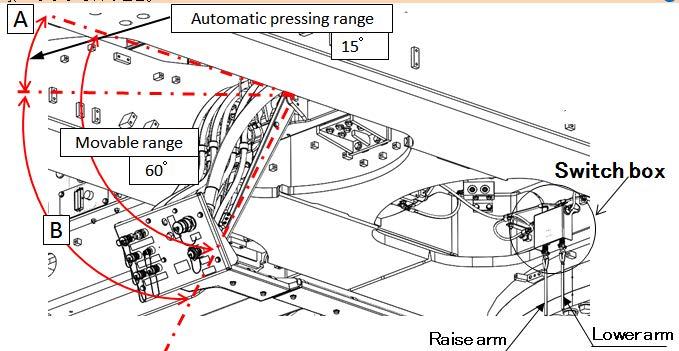
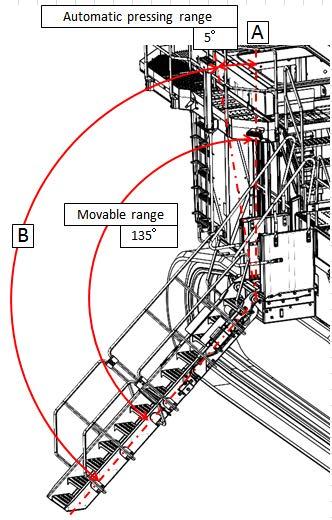
165 In assembly procedure No. A-6, 17 of the 60 mounting bolts of the revolving frame and swing circle were tightened. Tighten the other 43 bolts. (1)Start[Procedure]the engine (Follow the procedure given in assembly procedure A-56). (2)Swing the upper structure and tighten the bolts when they come to either one of the places marked (43 bolts). Assembly procedure Permanent tightening of swing circle boltA-59 Precautions Tools required Equipment required •Make sure to bleed air from each part before swinging the upper structure. Name Q’ty Name Q’ty 55 mm Socket Others Width across flats: 55 3 Tightening torque : 2,452 – 3,040 Nm {250 – 310 kgm} Tighten this bolt. Apply LT-2. Target center torque: 280 kgm


166
After
assembling the large-sized hydraulic excavator in the field, touch up the following parts. When the machine is used on the seashore etc. where it is rusted easily, touch up the following parts, too. Unpainted parts of machined surfaces of flanges after installing piping Grease tubes Metallic hose bands, etc. Use rust-preventive clear paint for touching up the machined surfaces etc. (Recommended brand: KOMATSU genuine rust-preventive clear paint) Assembly procedure Parts to be touched up after field assembly (chassis side)A-60 Precautions Tools required Equipment required Name Q’ty Name Q’ty Others Underside of counterweight
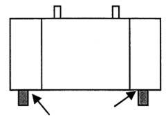
167 Assembly procedure Connection of engine heater connection port (1/3)A-61 Precautions Tools required Equipment required Name Q’ty Name Q’ty Air impact wrench 1117 mm Socket 119 mm Socket 1Extension L200 Others No.Part No.Parts F-51F-5001024-81230Bolt4nameQ'ty 01024-81016 Bolt2 F-52 04434-51012 Clip1 F-53 04434-51912 F-55F-5401024-81230Bolt1Clip1 04434-51012 Clip1 F-56 04434-51912 F-5801024-81230Bolt1F-57195-33-11220Spacer1Clip1

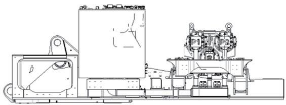


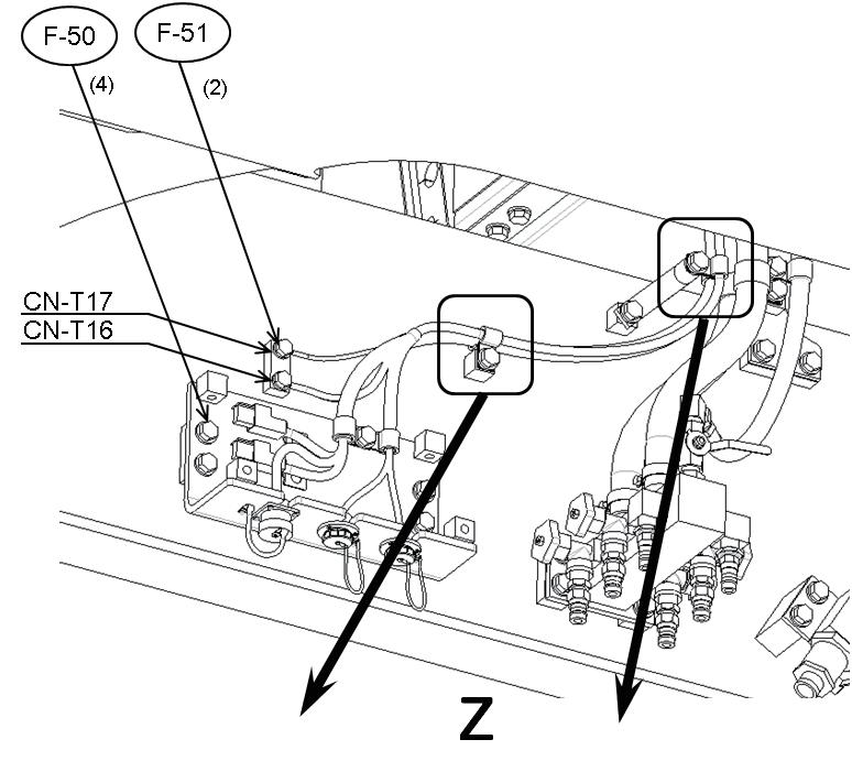

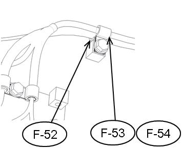


168 Assembly procedure Connection of engine heater connection port (2/3)A-61 Precautions Tools required Equipment required Name Q’ty Name Q’ty Others Color of hose distingush tape: white Connection (face seal) 1 point Connection2pointsF-66 F-65 F-61 F-62 F-63 F-64 F-59 F-60 No.Part No.Parts F-61F-6001024-81230Bolt4F-5921T-06-31570-NKBracket1nameQ'ty 04434-53412 Clip2 F-62 01024-81245 F-65F-6401024-81230Bolt1F-6304434-51912Clip1Bolt1 02896-61012 F-6607281-00419Clamp2O-ring1 Air impact wrench 1119 mm Socket 1Extension L200
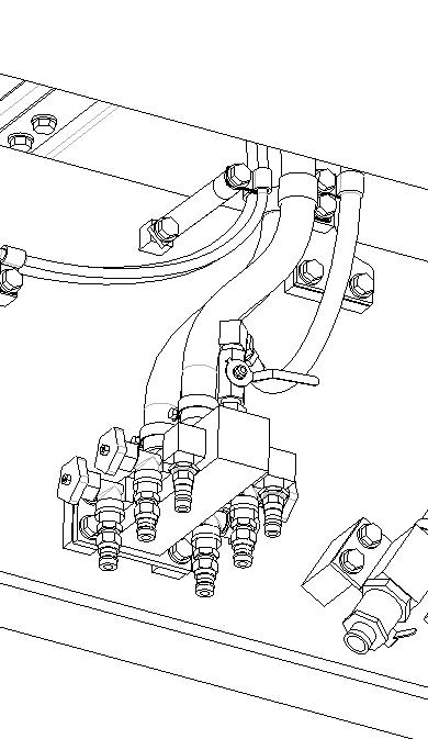
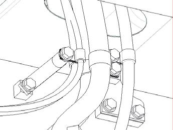

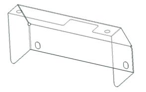


169 Assembly procedure Connection of engine heater connection port (3/3)A-61 Precautions Tools required Equipment required Note)After the procedure (1) is finished, perform the procedure (2). Name Q’ty Name Q’ty Others Connection port Open Close •Turn the knob clockwise to close the CloseClosevalves. Engine left front side Engine right side •Turn the knob counterclockwise to open the valves. (1)Confirm that the 5 valves (a mark) of connection ports are closed. (2)Open 2 valves (A mark) around the engine. Open
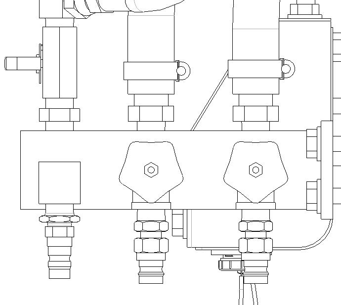
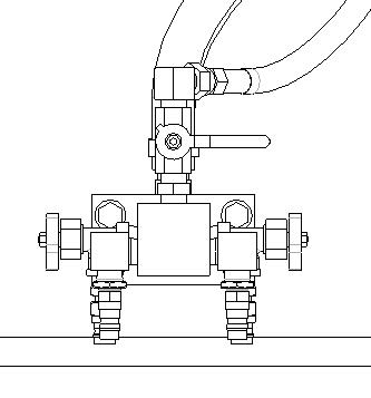
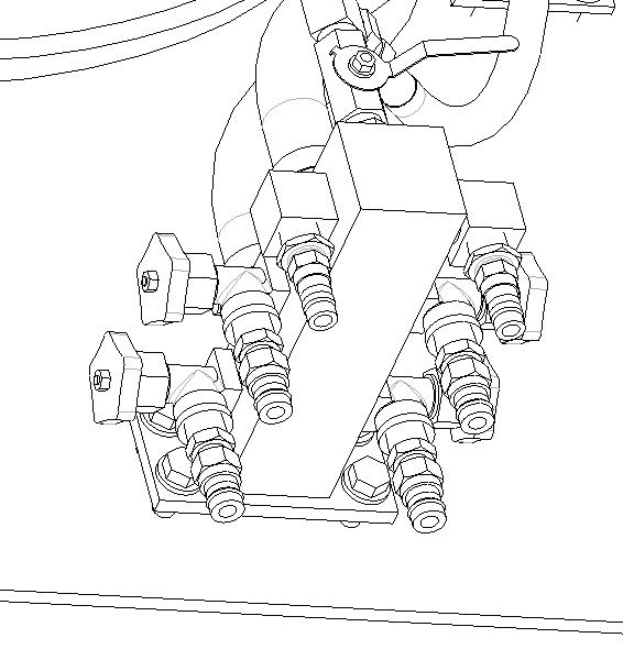
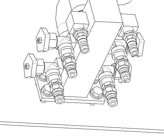
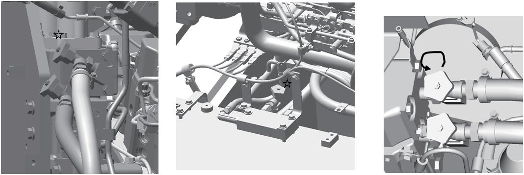
170 Assembly procedure Installation of optional harnessA-62 Precautions Tools required Equipment required Name Q’ty Name Q’ty Others Connection No.Part No.Parts nameQ'ty F-67 01024-81250Bolt1 F-68 04434-51712Clip1 F-69 195-33-11220Spacer1 Service center specification Additional emergency stop switch specification 676869 P P Air impact wrench 1119 mm Socket 1Extension L200
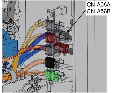
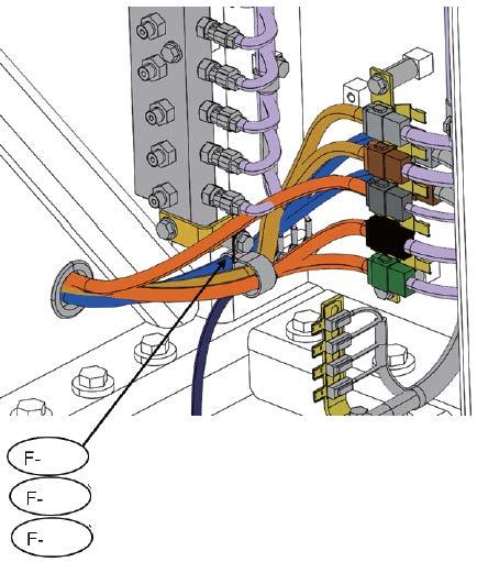
171 Installation position of KomVision camera and rear lamp Assembly procedure Installation of KomVision and rear lamp (1/9)A-63 Precautions Tools required Equipment required Name Q’ty Name Q’ty Others Komvision camera Camera ② Camera ① Camera ⑥ Camera ③ Rear lamp Camera ⑤ RearCameralamp ④ & ⑧ Camera ⑦ Camera ① Camera ② Camera ③ Camera ④ & ⑧ Camera ⑤ Camera ⑥ Camera ⑦ Camera⑧ Camera④
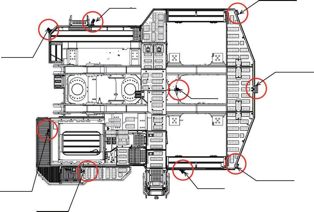
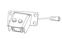


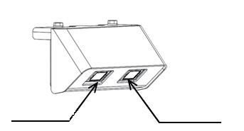


172 Installation of KomVision camera Assembly procedure Installation of KomVision and rear lamp (2/9)A-63 Precautions Tools required Equipment required Name Q’ty Name Q’ty Others No.Part No.Parts nameQ'ty C 85 01024-81225Bolt12 C 86 01024-81235Bolt4 a Insert connector in cab base and contact with inside connector (CN-CAM1) a Insert connector in cab base and contact with inside connector (CN-CAM6) a Insert connector with inside connector (CN-CAM5) Air impact wrench 1119 mm Socket 1Extension L200 C-86 C-85 C-85 C-85 a Insert connector with inside connector (CN-CAM4, CN-A40)
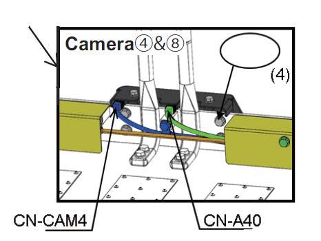
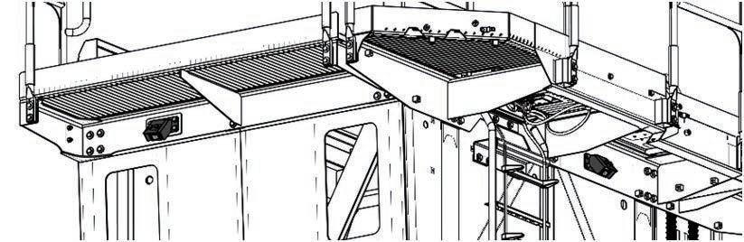
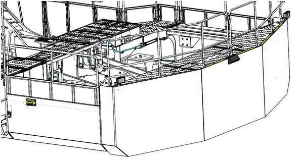

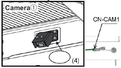
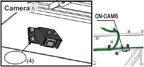
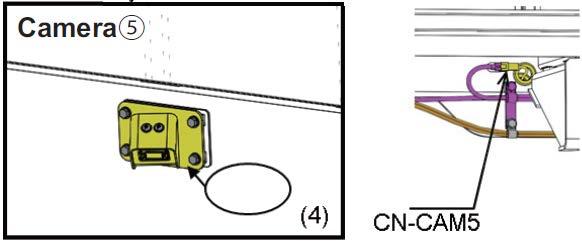
173 Assembly procedure Installation of KomVision and rear lamp (3/9)A-63 Precautions Tools required Equipment required Name Q’ty Name Q’ty Others No.Part No.Parts nameQ'ty C-87 01024-81230Bolt8 C-88 01024-81225Bolt2 ※ Remove cover and connect with chassis harness connector (CN-CAM3). C-88 ※Connect with chassis harness connector (CN-CAM7). ※ Remove cover and connect with chassis harness connector (CN-CAM2). C-87C-87 Air impact wrench 111Extension L200 Socket 19 mm in width across flats
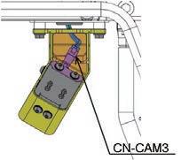
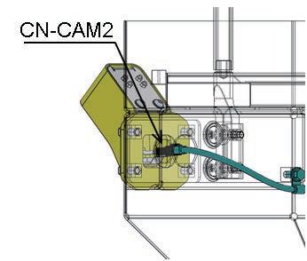
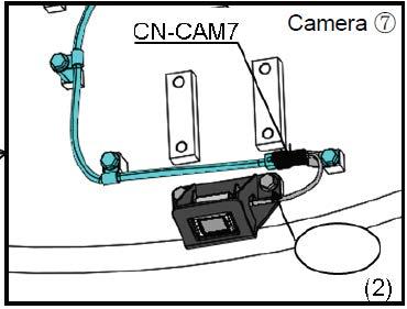
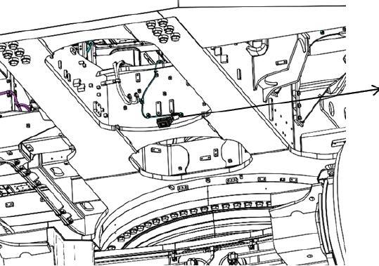

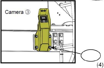
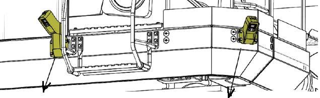
174 Installation of KomVision harness Assembly procedure Installation of KomVision and rear lamp (4/9)A-63 Precautions Tools required Equipment required Name Q’ty Name Q’ty Others Connect connector CN-A77 Connect connector. Refer to CN-A72BCN-A72AA-17 Connect connector. Refer to A-19 CN-A74 Connect connector. Refer to A-31 CN-A29CN-A39 Connect connectorCN-A75Install wiring in the field. Air impact wrench 111Extension L200 Socket 19 mm in width across flats
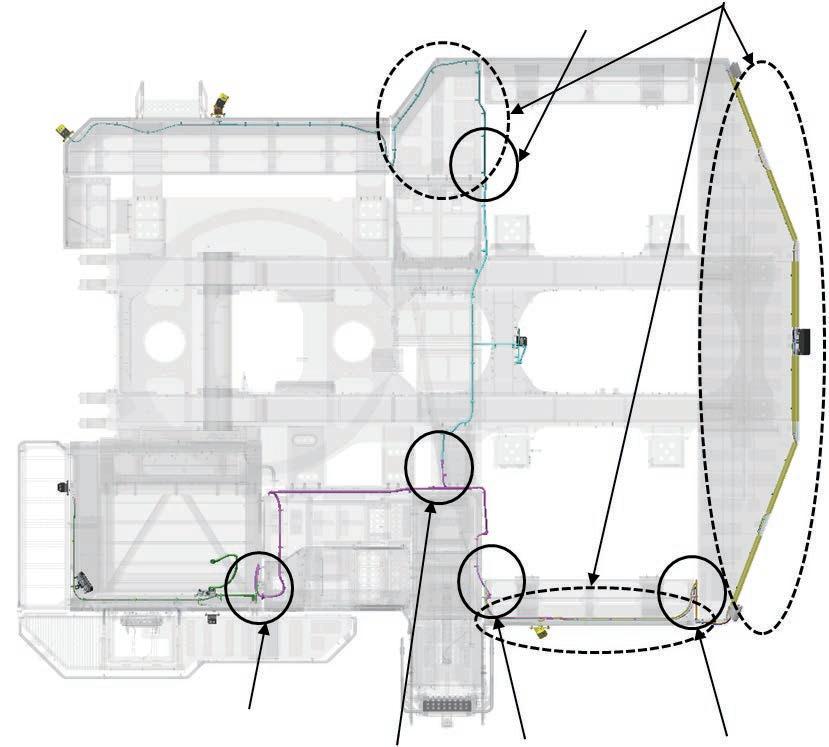
175 Installation of KomVision harness Assembly procedure Installation of KomVision and rear lamp (5/9)A-63 Precautions Tools required Equipment required Name Q’ty Name Q’ty Others No.Part No.Parts nameQ'ty C 89 04434-51712Clip13 C 90 01024-81225Bolt13 Right deck a Install the harness which is installed to right catwalk. C-89 C-90 Air impact wrench 111Extension L200 Socket 19 mm in width across flats

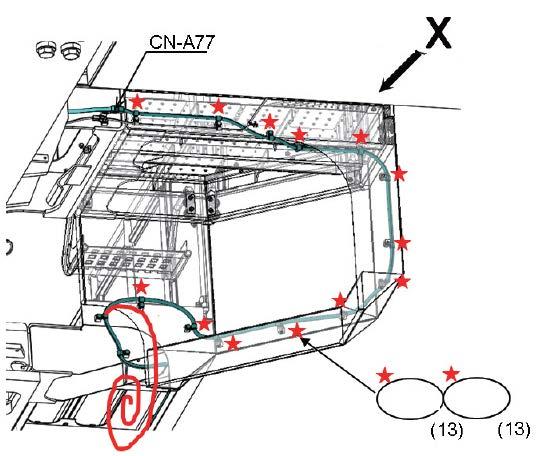
176 Assembly procedure Installation of KomVision and rear lamp (6/9)A-63 Precautions Tools required Equipment required Name Q’ty Name Q’ty Others No.Part No.Parts nameQ'ty C 91 21T-06-44212Harness1 C 92 21T-06-32980Harness1 C 93 04434-51412Clip3 C 94 04434-51012Clip3 C 95 01024-81250Bolt1 C 96 01024-81230Bolt2 C 97 198-911-6170-NKBracket2 C 98 04434-51712Harness2 C 99 01024-81225Bolt2 C 100 04435-51012Clip4 C 101 04434-51412Clip4 C 102 01024-81225Bolt4 a Install the harness installed to left deck and the loose-supply harness. Air impact wrench 111Extension L200 Socket 19 mm in width across flats W W C-100 C-101 C-102 C-97 C-98 C-99 C-93 C-94 C96 C-93 C-94 C-95 C-9C-912Rear camera harness (if equipped)Rearlamp harness (if equipped)
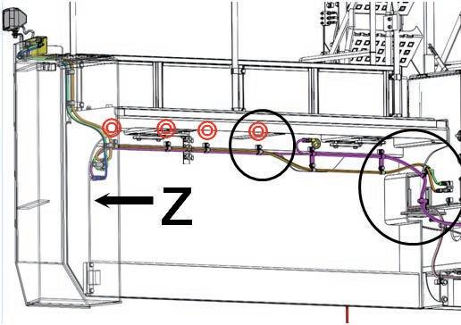
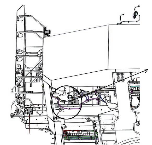

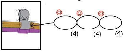

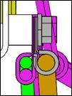

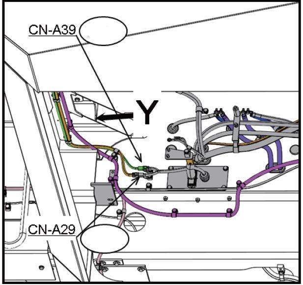
177 Assembly procedure Installation of KomVision and rear lamp (7/9)A-63 Precautions Tools required Equipment required Name Q’ty Name Q’ty Others No.Part No.Parts nameQ'ty C 103 205-03-71331Collar1 C 104 04434-51012Clip1 C 105 04434-51412Clip1 C 106 01024-81270Bolt1 C 107 04435-51012Clip3 C 108 04434-51412Clip3 C 109 01024-81225Bolt3 Air impact wrench 111Extension L200 Socket 19 mm in width across flats Z V V C-103 C-104 C-105 C-106 C-107 C-108 C-109
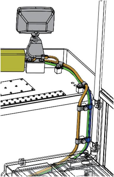

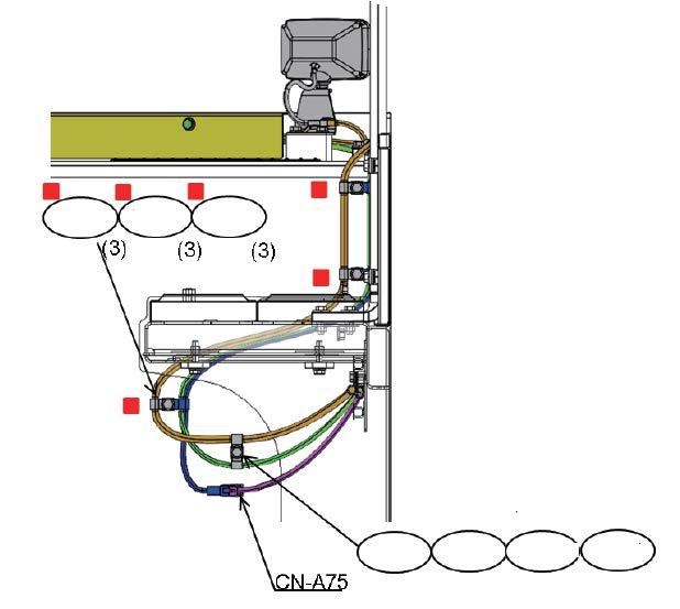
178 Assembly procedure Installation of KomVision and rear lamp (8/9)A-63 Precautions Tools required Equipment required Name Q’ty Name Q’ty Others No.Part No.Parts nameQ'ty C 110 04435-51012Clip13 C 111 04434-51412Clip13 C 112 01024-81225Bolt13 C 113 21T-06-41690-NKCover2 C 114 21T-06-41671-NKCover1 C 115 01024-81225Bolt6 C 116 21T-06-33360Bracket1 C 117 01024-81225Bolt2 C 118 08193-21012Clip1 C 119 20Y-06-43230 Work Lamp Ass'y 2 Air impact wrench 111Extension L200 Socket 19 mm in width across flats C-114 C-115 C-113 C-115 C-110 C-111 C-112C-110 C-111 C-112 C-116 C-117 C-118 C-119 C-113 C-115
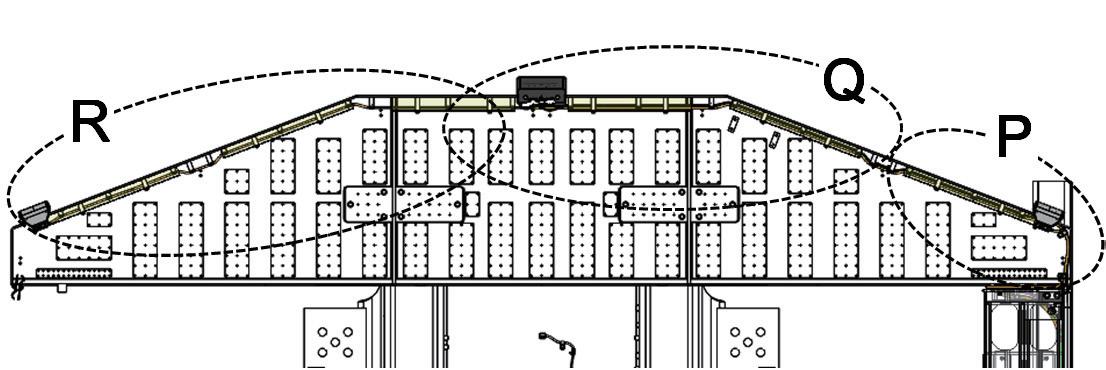

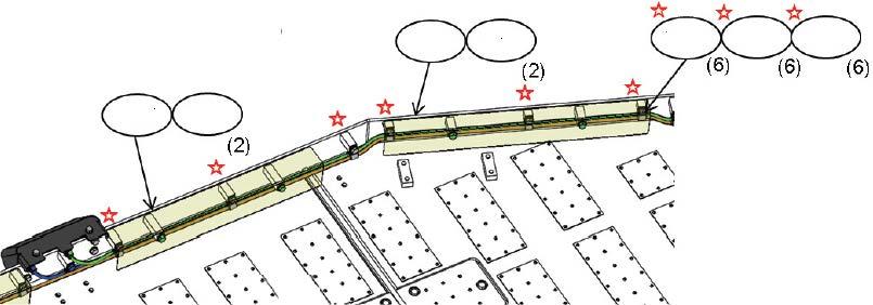
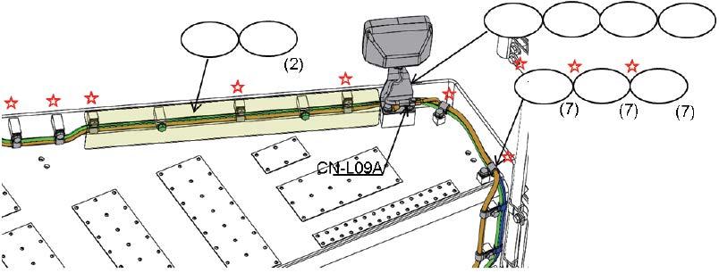

179 Assembly procedure Installation of KomVision and rear lamp (9/9)A-63 Precautions Tools required Equipment required Name Q’ty Name Q’ty Others No.Part No.Parts nameQ'ty C 120 04434-51012Clip11 C 121 01024-81225Bolt11 C 122 21T-06-41690-NKCover2 C 123 21T-06-41671-NKCover1 C 124 01024-81225Bolt6 C 125 21T-06-33360Bracket1 C 126 01024-81225Bolt2 C 127 08193-21012Clip1 C-128 20Y-06-43230 1Work Lamp Ass'y Air impact wrench 111Extension L200 Socket 19 mm in width across flats For calibration of KomVision, refer to the procedure M-9. C-125 C-126 C-127 C1-28 C-122 C-125 C-122 C-125 C-123 C-125 C-120 C-121

180 Assembly procedure Connection of emergency stop switch (if equipped) (at the right below power module)A-64 Precautions Tools required Equipment required Name Q’ty Name Q’ty Others Machine left Machine front No.Part No.Parts nameQ'ty F-70 01024-81220Bolt2 F-71 04434-51012Clip2 F-72 21T-06-31141Rope(Red)1 F-73 21T-06-31170Shackle1 Air impact wrench 111Extension L200 Socket 19 mm in width across flats Z 70 70 71 71 7374

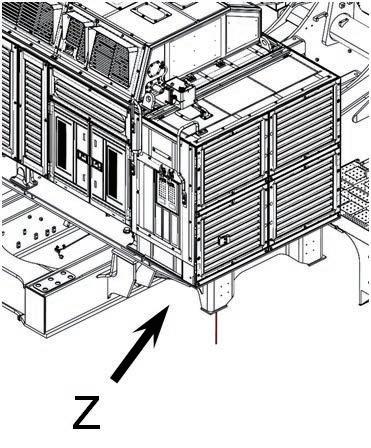
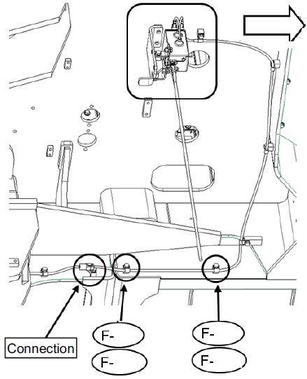
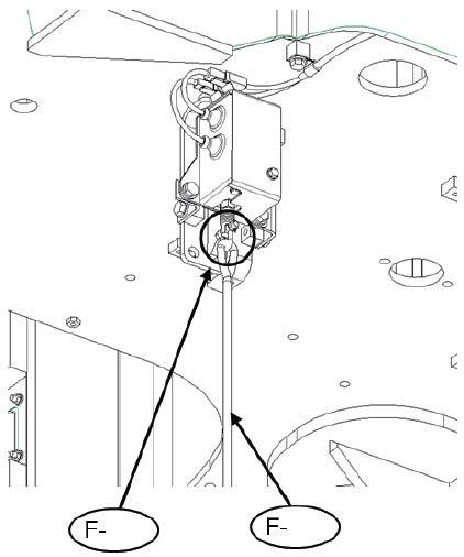
181 Assembly procedure Connection of emergency stop switch (if equipped) (at the left side of ladder)A-65 Precautions Tools required Equipment required Name Q’ty Name Q’tyMachineOthers left Machine front No.Part No.Parts nameQ'ty F-74 21T-06-41130Rope(Red)1 F-75 21T-06-31170Shackle1 P P 74 75
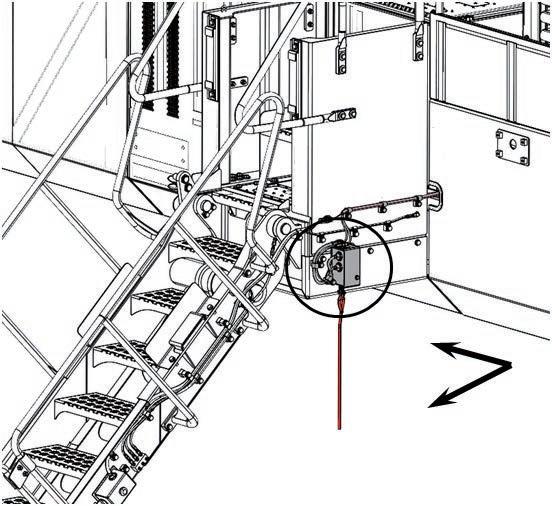
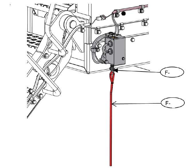
182 This page is for service center installed machine. Assembly procedure Installation of engine oil and PTO oil pipingsA-66 Precautions Tools required Equipment required Name Q’ty Name Q’ty 1 Screwdriver (Socket 7mm ) 1 Air Impact wrench 1 Others (1) Clamp the engine oil hose fixed at the power container to revolving frame and install the tip of the hose to service center port. (2)Install the tip of PTO oil hose fixed at the revolving frame to PTO valve. No.Part No.Parts nameQ'ty F-76 281-01-13180Clip3 F-77 01024-81225Bolt3 F-78 07281-00419Clamp1 F-79 07281-00259Clamp1 Socket 19 mm in width across flats 77 76 mark position 78 79

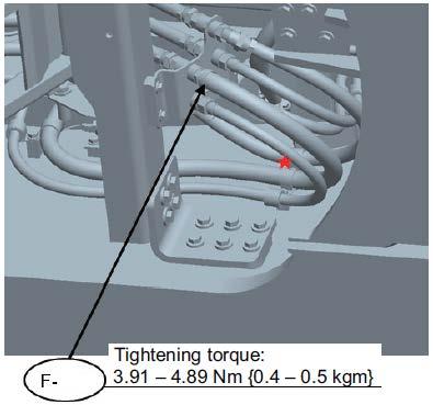
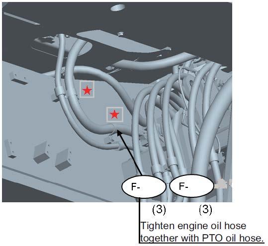
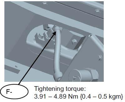

183 a This page is for service center installed machine. Assembly procedure Installation of coolant pipingA-67 Precautions Tools required Equipment required Name Q’ty Name Q’ty 1 Others No.Part No.Parts nameQ'ty F-80 07281-00419Clamp1 Install the coolant hose fixed at the revolving frame to radiator lower piping valve. 80 Screwdriver (Socket 7mm )

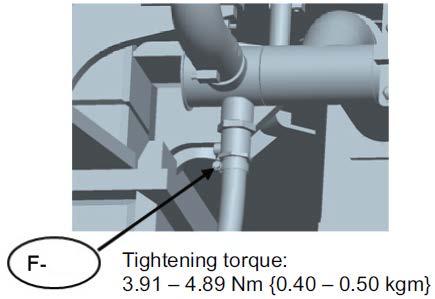
184 This item is for service center specification only Assembly procedure Installation of guard bracket (if equipped)A-68 Precautions Tools required Equipment required Name Q’ty Name Q’ty Others Front of machine Left of machine No.Part No.Parts nameQ'ty F-81 21T-46-31161-NKBracket1 F-82 01010-82050Bolt4 F-83 01643-32060Washer4 Air impact wrench 111Extension L200 Socket 30 mm in width across flats 81 8283

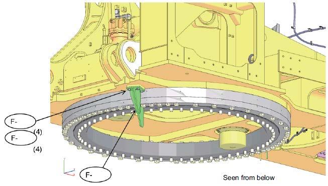
185 C.ASSEMBLY OF BACKHOE
186 Method of slinging boom cylinder for installation Assembly procedure Installation of boom cylinder (1/2)C-1 Precautions Tools required Equipment required Since you can install the boom cylinder in reverse without realizing, check its direction before installing it. Name Q’ty Name Q’ty Hammer 1 36 mm Socket 1 ø12, 5 m Wire 2 ø16, 5 m Wire 1 SC14 Shackle 1 8 t Crane 1 Air Impact wrench 1 Others Boom Weight:cylinder2,100 kg/each Pay attention to the mounting direction of the boom cylinder! The tube on the cylinder bottom side must be on the upper side.
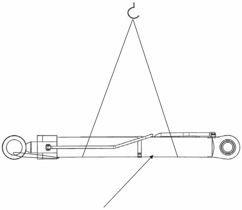
187 Assembly procedure Installation of boom cylinder (2/2)C-1 Precautions Tools required Equipment required 1.The bushings are press fitted to the revolving frame and the parts marked with A are tightened temporarily when the machine is shipped. 2.Before inserting the pins, apply grease to the pin holes (inside of the bushings). a When installing the plates, hold them with wires etc. so that you will not catch your fingers in them. NameQ’tyNameQ’ty Others BoomLeftcylinder H = 2000 Right O-ring Side of center of machineofOutsidemachine Pin, weight: 93.8 kg (2 places) (2 places) (2 places)Plate, bolt, washer (hasBushingbeen press fitted) (outside) (hasBushingbeen press fitted) (inside) Install only the shims 16 mm thick on inside of the machine and adjust the clearance by changing the quantity of the shims on outside of the machine. No.Part No.Parts (1)Remove[Procedure]H-607000-15180O-ring4H-521T-70-31690Shim8H-421T-70-31470Shim8H-321T-70-31421Shim2H-2707-H1-X5770-NKCylinder,H-1707-H1-X5760-NKCylinder,nameQ'tyLH1RH1thepartsmarkedwith A which are installed to the revolving frame temporarily. (2)Clean the pins and inside of the bushings. (3)Sling the cylinder and position it to the pin hole. (4)Install the O-ring to the cylinder bushing. (5)Set the shims and spacer and install the parts marked with A Reduce the clearance marked with to 1 mm or (6)Performless. this procedure for the right and left boom cylinderClearancefeet. between pin and revolving frame bushing: 0.098 – 0.310 mm Clearance between pin and boom cylinder bushing hole: 0.043 – 0.131 mm ba a=185mm=365mm Shim (H-3, H-4 ,H-5) Air impact wrench 111Extension L200 Socket 36 mm in width across flats
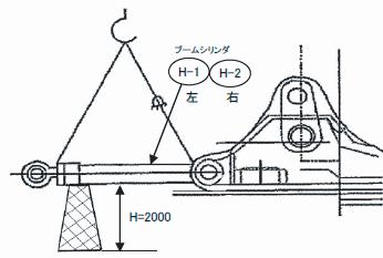
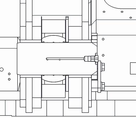


188 Remove the oil stopper from the boom cylinder piping and revolving frame piping, and then install the 4 hoses as shown in the following figure. a When removing the oil stopper, take care that oil may spout out. Use the split flanges, bolts, etc. used to install the oil stopper (on the machine hose side) as they are. Assembly procedure Installation of boom cylinder hosesC-2 Precautions Tools required Equipment required 1.Take care not to twist the hoses when 2.Takeinstalling.care not to catch the O-rings in the parts (Apply grease to them before 3.Afterinstalling).connecting the hoses, bleed air from the boom cylinder. 4.Tighten the hoses from the revolving frame side (to prevent them from twisting). a Keep the cylinder horizontally when bleeding air. Name Q’ty Name Q’ty 22 mm Socket 1 27 mm Socket 1 200 mm Extension 1 Air Impact wrench 1 Others Tightening torque : 343 – 425 Nm {35 – 43.5 kgm} O-ring Hose inside #14 L=1930 O-ringHose outside #20 L=2940 No.Part No.Parts H-1021T-64-41850Hose2H-921T-64-41860Hose2H-807000-B3048O-ring4H-707000-B2060O-ring4nameQ'ty Parts to install oil stopper (on cylinder side) #20 07371-52080Hose (Flange) × 8 pcs.:Reuse 01010-81865 (Bolt) × 16 pcs.:Reuse 01643-31845 (Washer) × 16 pcs.:Reuse 07000-B2060 (O-ring) × 4 pcs.:Keep 07378-12010 (Head) × 4 pcs.:Keep #14 07371-51470Hose (Flange) × 8 pcs.:Reuse 01010-81455 (Bolt) × 16 pcs.:Reuse 01643-31445 (Washer) × 16 pcs.:Reuse 07000-B3048 (O-ring) × 4 pcs.:Keep 07378-11410 (Head) × 4 pcs.:KeepNo.Part No.Parts H-4921T-64-32990Bolt16H-4821T-64-32980Adapter4H-4701643-31445Washer16H-4601010-81455Bolt16H-4507371-51470Flange8H-4407000-B3048O-ring4nameQ'ty Hexagon socket 14 mm in width 1across flats
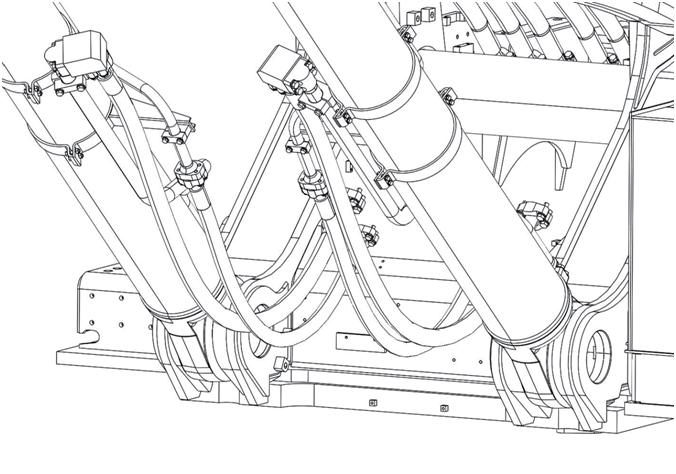

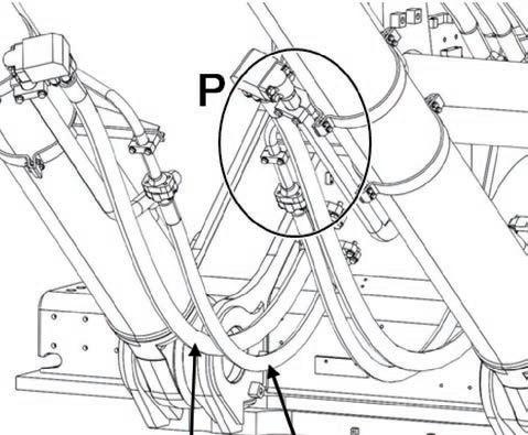
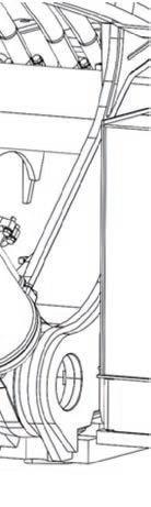

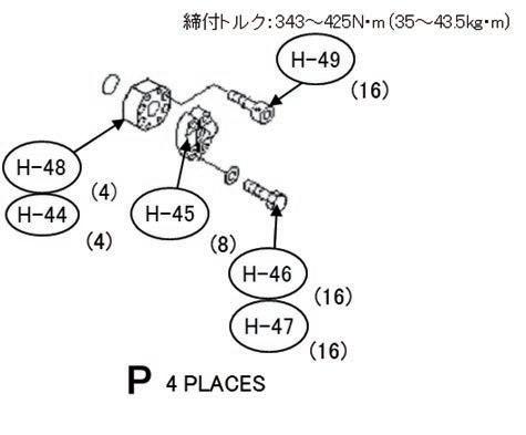


189 Assembly procedure Assembly of boom sub assembly (1/5)C-3 Precautions Tools required Equipment required 1.Take care not to catch the O-rings in the parts (Apply grease to them before 2.Securelyinstalling).take measures to prevent the arm cylinder from projecting. 3.Use some split flanges, bolts, etc. used to install the oil stoppers as they are. Name Q’ty Name Q’ty 19 mm Socket 1Lift work stand 1 22 mm Socket 1 27 mm Socket 1 300 mm Extension 1 200 mm Extension 1 Air Impact wrench 1 Others 1. Installation of work equipment piping (tubes) No. Part No. Parts name Q'ty H-11 21T-64-39140-NK Tube 1 H-12 21T-64-39150-NK Tube 1 H-13 21T-64-39160-NK Tube 1 H-14 07000-B3048 O-ring 2 H-15 07000-B2060 O-ring 7 H-16 01643 31845 Washer 12 H-17 01010-81865 Bolt 12 17 1717
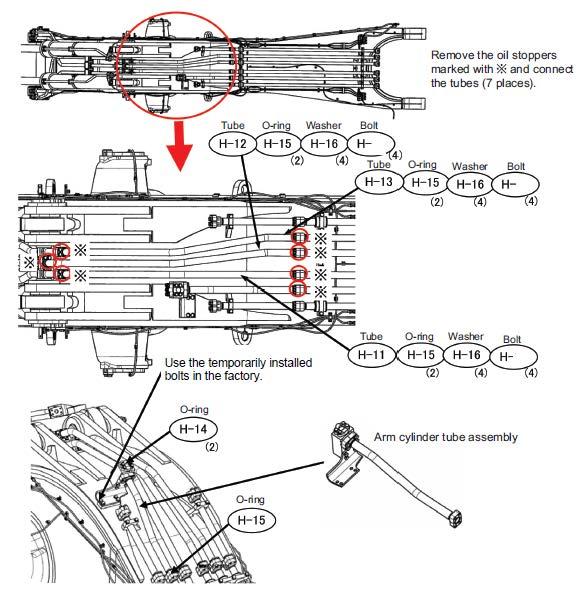
190 2.Installation of arm cylinder
Assembly procedure Assembly of boom
Plates, bolts and washers
Fix the arm cylinder rod securely so that it will not come out during work. sub assembly LeftRightcylinder
O-ring Set shims on both inside and outside. Pin (1)Remove[Procedure] the pin from the boom. (2)Clean the pin and inside of the bushing. (3)Install the O-ring to the cylinder bushing. (4)Sling the cylinder and set it to the pin hole. (5)Set the shim and install the pin. (6)Perform the above procedure for the right and left arm cylinders. No.Parts
H-2221T-70-31441-SAShim4H-2107000-12140O-ring4H-20707-H1-X5790-NKCylinder,H-19707-H1-X5780-NKCylinder,nameQ'tyLH1RH1Shim(H-22)
(2/5)C-3 Arm
No.Part
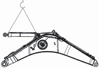
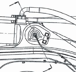
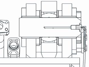
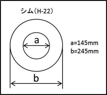
191 3.Installation of work equipment piping (hoses) Assembly procedure Assembly of boom sub assembly (3/5)C-3 Precautions Tools required Equipment required 1.Take care not to catch the O-rings in the parts (Apply grease to them before 2.Securelyinstalling).take measures to prevent the arm cylinder from projecting. 3.Adjust the hoses so that they will not be twisted. Name Q’ty Name Q’ty Others Hose#14 Hose#14 Hose#20O-ring O-ring O-ring Flange cylinderonside Flange cylinderonside Flange cylinderonside Washer on cylinder side Washer on cylinder side Washer on cylinder side Bolt cylinderon side Bolt cylinderon side Bolt cylinderon side H-24 H-27 H-28 H-30 H-32 H-23 H-26 H-29 H-31 H-33 H-25 H-27 H-28 H-30 H-32 No.Part No.Parts H-2707000-B3048O-ring4H-2607000-B2060O-ring4H-2507085-C1420Hose1H-2407085-C1418Hose1H-2307084-C2022Hose2nameQ'ty No.Part No.Parts H-3301010-81865Bolt8H-3201010-81455Bolt8H-31H-3001643-31445Washer8H-2907371-52080Flange4H-2807371-51470Flange4nameQ'ty01643-31845Washer8Remove the oil stoppers from the boom piping (tubes) and arm cylinder piping, and then install the 4 hoses as shown in the following Connectingfigure.parts: 8 places marked with ※ Use the split flanges, bolts, etc. used to install the oil stoppers on the tube side as they Partsare.toinstall oil stoppers (on tube side) #20 07371-52080Hose (Flange) × 4 pcs.:Reuse 01010-81865 (Bolt) × 8 pcs.:Reuse 01643-31845 (Washer) × 8 pcs.:Reuse 07000-B2060 (O-ring) × 2 pcs.:Keep 07378-12010 (Head) × 2 pcs.:Keep #14 07371-51470Hose (Flange) × 4 pcs.:Reuse 01010-81455 (Bolt) × 8 pcs.:Reuse 01643-31445 (Washer) × 8 pcs.:Reuse 07378 11410 (Head) × 2 pcs.: 07000-B3048 (O-ring) × 2 pcs.: KeepKeep

192 4.Installation of working lamps Assembly procedure Assembly of boom sub assembly (4/5)C-3 Precautions Tools required Equipment required a When installing the seal (209-72-11311), take care of the direction of its lip so that the grease can come out from inside. Name Q’ty Name Q’ty Others Install work equipment lamps as shown at left and connect their wires. 4 places on right and left of boom. Working lamp See pageBracket(5/5) WasherBolt Bolt Clip No.Part No.Parts nameQ'ty H-3420Y-06-43230Working lamp H-39209-72-11311H-3801024-81225H-3701010-81430H-3601643-31445Washer4H-3520Y-06-21551Bracket4ass’y4Bolt4Bolt4Seal4 H-40 21T-70-31290 Seal 2 H-41 08193-21012 Clip 4 H-41 See page (5/5)
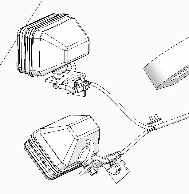

193 Assembly procedure Assembly of boom sub assembly (5/5)C-3 Install the seal as seen in figure below. 4 places on right and left of boom. Seal (2) H-40 Top side Seal Bottom side
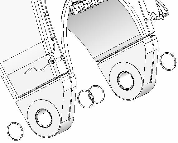
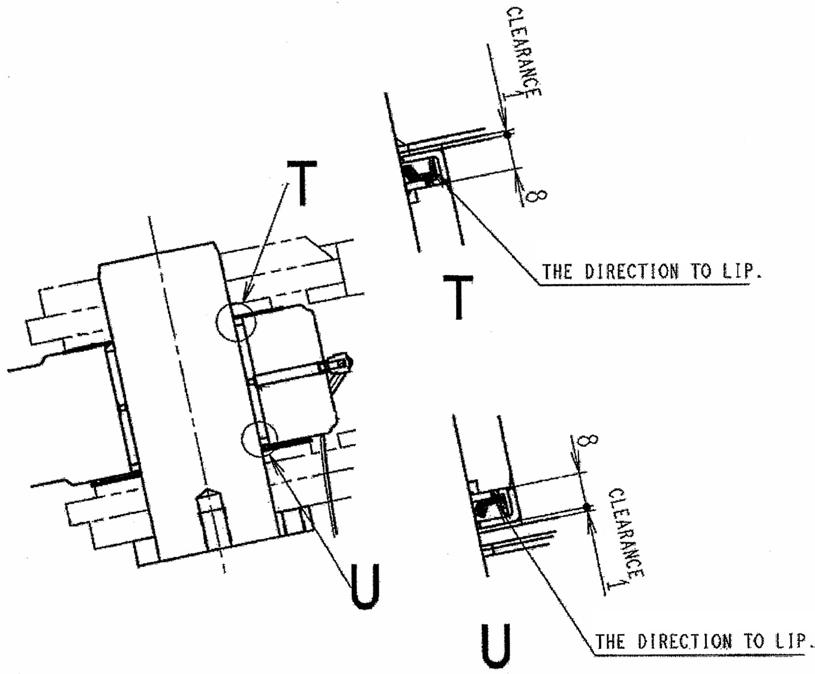
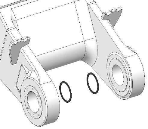
194 1.Slinging method Assembly procedure Installation of boom assembly (1/2)C-4 Precautions Tools required Equipment required 1.Appoint a worker to act as a signalman for the crane operator. 2.Do not go under a raised load. 3.Check that the wires are fitted properly to the 4.Whenhook.working, securely fix the arm cylinder rod to prevent it from projecting. a Take care that wooden blocks will not be driven out. Name Q’ty Name Q’ty Hammer 1Lift work stand 1 36 mm Socket 1 ø30, 5 m Wire 4 SB55 Shackle 4 45t Crane 1 Air Impact wrench 1 Others 45 t Crane Apply wooden blocks (about 100 mm square) to protect grease piping and wiring harness. 30 × 5 m wire × 4 pcs. + SB55 shackle × 4 pcs. Hook hole diameter: 80 Boom Weight:assembly23,900kg a Sling horizontally.
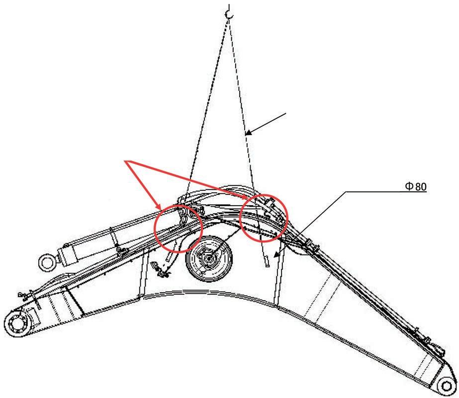
1.There are bushings press fitted to the revolving frame and boom, and the parts marked with ※ are installed temporarily for 2.Inserttransportation.thepinfrom the lower side of the 3.Takeground.care not to catch the seals in the 4.Beforeparts. inserting the pin, apply grease to the inside of the bushing.
(1)Remove[Procedure] the parts marked with ※ which are installed to the revolving frame temporarily. (2)Clean the pins and inside of the bushings. (3)Set the boom as shown above so that the clearances at the parts marked with on the right and left sides will be even and then decide the thickness and quantity of the shims to reduce the clearance to 1 mm or less. (4)Assemble the shims and pins. Clearance between pin and revolving frame bushing: 0.128 – 0.278 mm Clearance between pin and boom foot bushing hole: 0.386 – 0.562 mm (5)Perform this procedure for the right and left boom feet.
195 2.Installation of boom foot pin Assembly procedure Installation of boom assembly (2/2)C-4 Precautions Tools required Equipment required
Boom Revolvingassembly frame Shim Shim H-43 H-42 Insert shims on only outside of machine. Shim (H-40, H-41) No.Part No.Parts nameQ'ty H-42 21T-70-31480Shim8 H-43 21T-70-31490Shim16
Name Q’ty Name Q’ty Others Bushing (has been press fitted) (outside) Bushing (has been press fitted) (inside) Pin, Weight: 87.9 kg Plate, bolt, washer Bushing (has been press fitted) (boom foot) (2 places) (2 places) (2 (2(2places)places)places)
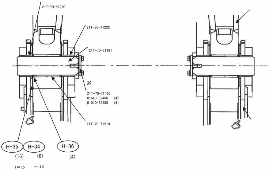
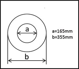
196 Assembly procedure Installation of boom cylinder head side (1/2)C-5 Precautions Tools required Equipment required 1.When slinging the boom cylinder, do not install the wire directly to its rod or body. (Protection of rod) 2.Bleed air from the cylinder. (See C-14.) Name Q’ty Name Q’ty Hammer 1 36 mm Socket 1 200 mm Extension 1 ø2, 5 m Wire 1 ø16, 5 m Wire 2 45t Crane 1 Air Impact wrench 1 Others 45 t Crane 16 × 5 m Wire Boom cylinder Boom cylinder top pin Boom top G.L. (Ground level) (1)After[Procedure]inserting the boom foot pin, lower the boom with the crane until its top touches the ground. (2)Remove the ropes from the boom assembly. (3)Sling the cylinder with the wire as shown above. (4)Start the engine. (Low idle)

197 Assembly procedure Installation of boom cylinder head side (2/2)C-5 Precautions Tools required Equipment required 1.The bushings are press fitted to the boom assembly and the parts marked with ※ are tightened temporarily when the machine is shipped. 2.When inserting each pin, check that the O-ring of the cylinder is not caught. 3.Check that pins and inside of the bushings are clean. 4.Extend and retract the boom cylinder carefully with the engine at low idle. Do not operate a lever other than the boom control lever. 5.Before inserting each pin, apply grease to the pin hole (inside of the bushing). Name Q’ty Name Q’ty Others Bushing, press fitted already (outside) Pin, Weight: 98.4 kgPlates, bolts and washers O-ring 21T-70-31240 (2 places) Bushing, press fitted already (inside) 21T-70-31250 (2 places) 21T-70-31181 (2 places) 21T-70-71490 (2) 01643-32460 (4) 01010-82455 (4) No.Part No.Parts nameQ'ty H-50 07000-15180O-ring4 (5)Remove[Procedure] parts marked with ※ from the boom. (6)Clean the pin and inside of the bushing. (7)Sling the cylinder with wires. While extending and retracting it hydraulically, adjust the pin holes. (8)Install the seal, O-ring and pin and then install the cover. (Since the pin is heavy, sling it with a crane, taking care of safety.) Fit of pin and boom bushing ---- Clearance: 0.106 – 0.298 mm Fit of pin and boom cylinder ---- Clearance: 0.043 – 0.131 mm (9)Perform the above procedure for the right and left of the boom cylinder top. H-50
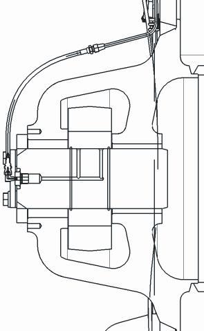
198 Assembly procedure Installation of hoses between boom and chassisC-6 Precautions Tools required Equipment required 1.Take care not to catch the O-rings in the (Applyparts. grease to them before installing.) 2.When the oil stopper is removed, oil spouts out. Take care. 3.Adjust the hoses so that they will not be Lightlytwisted.tighten the clamps on chassis side, adjust the hose directions, tighten the clamps on the work equipment side to the specified torque, then tighten the clamps on chassis side to the specified torque. 4.Connect the bucket cylinder pipings (marked with a) in Connection of bucket cylinder (C-9). Name Q’ty Name Q’ty 22 mm Socket 1 27 mm Socket 1 200 mm Extension 1 Air Impact wrench 1 Others O-ringI-1 BArm HArm BBucket BBucket HBucket BArm No.Part No.Parts I-107000-B2060O-ring6nameQ'ty Oil Tubestoppersside ※ 07071-52080(12) ※ 01643-31845(24) ※ 07378-12010(6)07000-B2060(6)01010-81835(24) Hose 21T-64-39620(6)07000-B2060(6)01010-81865(24)01643-31845(24)07371-52080(12)side (1)Remove[Procedure] the oil stoppers from the hoses and tubes. The parts marked with ※ will be reused to connect the hoses and tubes. (2)Connect the hoses and tubes (6 places).
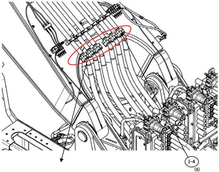
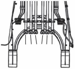
199 1.PreparationAssemblyprocedure Installation of arm assembly (1/3)C-7 Precautions Tools required Equipment required •Before inserting the pin, apply grease to the inside of the bushing. •Fix the link securely so that the bucket cylinder will not extend. Name Q’ty Name Q’ty Hammer 1 36 mm Socket 1 200 mm Extension 1 ø30, 5 m Wire 2 SB55 Shackle 2 45 t Crane 1 Air Impact wrench 1 Others 45 t Crane 45 t Crane 30 × 5 m wire × 2 pcs. + SB55 shackle × 2Fixpcs.the link section securely so that bucket cylinder will not be extended when assembly is slung. (1)Remove[Procedure] the parts marked with ※ which are installed to the boom top temporarily. (2)Clean the pins and inside of the bushings. Sling the arm assembly as shown in the left figure. (3)Press fit the seals to arm top, link and boom connecting boss. Arm Weight:assembly12,900 kg
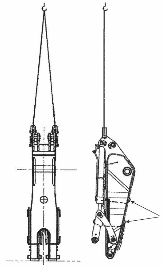
200 Assembly procedure Installation of arm assembly (2/3)C-7 Precautions Tools required Equipment required Install the seals so that they will not slant. Name Q’ty Name Q’ty Others No.Part No.Parts I-4209-72-11261Seal4I-321N-70-12160Seal4I-221T-70-31290Seal2nameQ'ty Arm linkFront Bucket side Arm A boss Wrist link Arm C boss
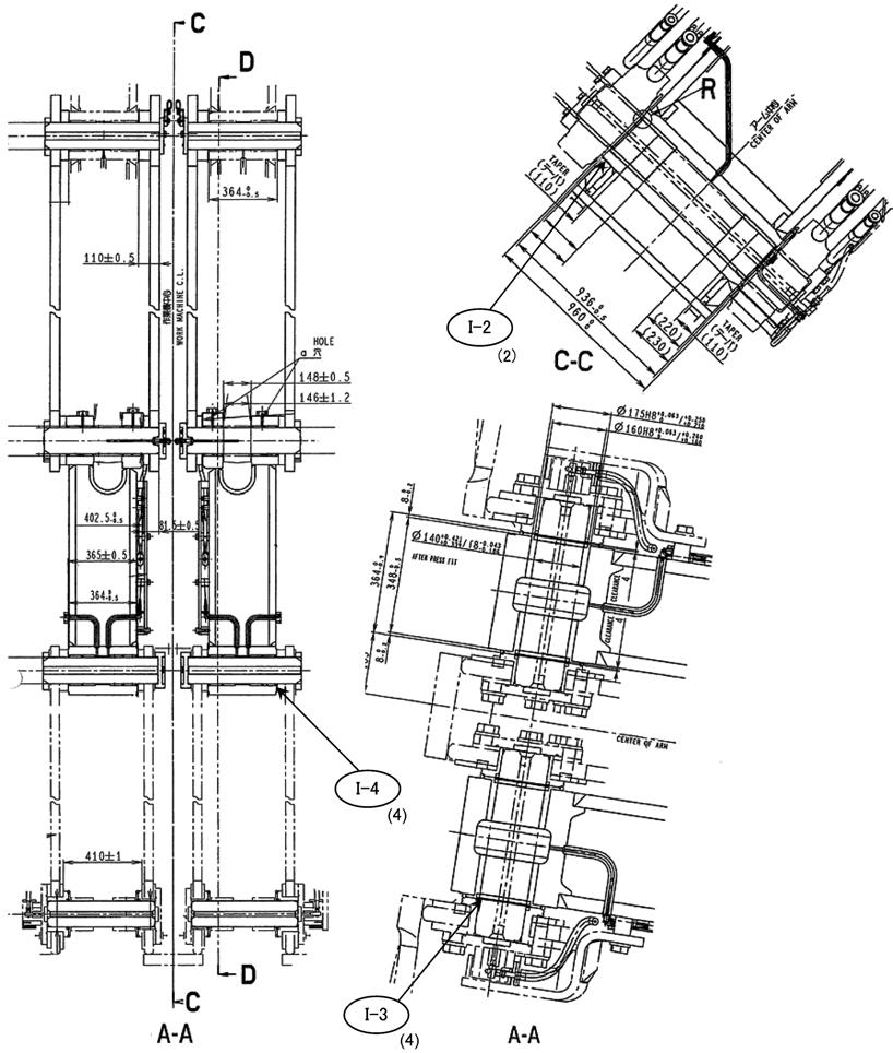
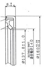

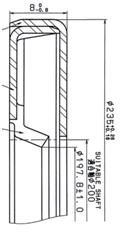


201 2.Installation of arm assembly Assembly procedure Installation of arm assembly (3/3)C-7 Precautions Tools required Equipment required 1.Take care not to catch the O-rings and seals in the parts. (Before fitting the O-rings, apply grease to 2.Therethem.)are bushings press fitted to the arm assembly and boom assembly, and the parts marked with ※ are installed temporarily for transportation. 3.Insert the shims in the right and left sides evenly. Name Q’ty Name Q’ty Hammer 1 36 mm Socket 1 200 mm Extension 1 ø30, 5 m Wire 2 SB55 Shackle 2 45t Crane 1 Nylon sling 1 Air Impact wrench 1 Others 45 t Crane tShim=1.5 Shimt=1 Shimt=9 tShim=12 O-ring (hasBushingbeen press fitted) 21T-70-32151 (2 places) Cover, bolt, washer Pin Shim (I-5~8) No.Part No.Parts t1.5I-821T-70-31820Shim1t12I-521T-70-31391Shim2nameQ'tyt9I-621T-70-31780Shim1t1I-721T-70-31810Shim1I-907000-15260O-ring2 (1)Raise[Procedure]and lower the boom several times. After the boom cylinder becomes easy to control finely, lower the boom slowly to align the holes. (2)Install the nylon sling to the pin and lift it up. (3)Set the arm as shown in the above figure and install it as shown in the figure below. Clearance between pin and boom bushing: 0.710 – 0.854 mm Clearance between pin and arm bushing: 0.520 – 0.703 mm (4)Adjust the clearance between the boom and arm to 1 mm or less with shims. Mobile elevating work platform 1

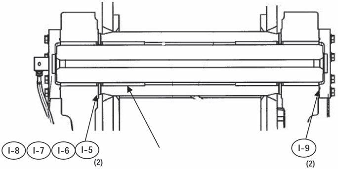

Boomcylinder No.Parts installed to the arm cylinder top tempins and inside of the bushthe O-ring to the cylinder bushing. the wire to the left arm cylinder assembly as shown in the figure at left. the rod fixing wire of only the left (6)Givecylinder.theoperator directions to operate the (7)Raisearm.or lower the crane and extend or retract the arm cylinder to align the Ifholes.thestroke is short, raise the boom a lit(8)Settle. the lock plate. this procedure similarly for the right arm cylinder top. between pin and arm bushing: 0.503 – 0.629 mm between pin and arm cylinder: 0.243 0.369 mm
(2)Cleanporarily.the
(5)Remove
(9)Perform
(4)Install
(1)Remove[Procedure]I-1021T-70-32181-SAShim4nameQ'tyI-1107000-12140O-ring4thepartsmarkedwith ※ which are
Clearance
202 Assembly procedure Installation of arm cylinderC-8 Precautions Tools required Equipment required 1.After connecting the hose, bleed air from the arm 2.Limitcylinder.the engine speed to low idle and do not move the cylinder to the stroke end. 3.Take care of the seals and O-rings. (Apply grease before fitting) 4.Align the holes carefully and do not put your hand/finger in the holes. 5.There are bushings press fitted to the arm assembly, and the parts marked with ※ are installed temporarily for transportation. 6.When slinging the arm cylinder, do not install the wire directly to its rod or body. 7.When extending and retracting the arm cylinder, limit the engine speed to low idle and operate the lever carefully. Do not operate the bucket. 8.Before inserting the pin, apply grease to the inside of the bushing. 9.Insert the shims in the inside and outside evenly. Name Q’ty Name Q’ty Hammer 1 36 mm Socket 1 200 mm Extension 1 ø12, 5 m Wire 1 45 t Crane 1 Air Impact wrench 1 Others 12 × 5 m Wire Arm cylinder top Arm
Clearance
(3)Installings.
–
Arm Section of arm cylinder top O-ringI-11 Shim Pin Lockplate, washer, bolt Bushing (has been press fitted) (2 places) (4 places) I-10 Shim (I-10) No.Part
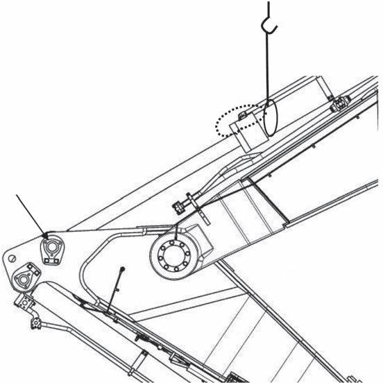
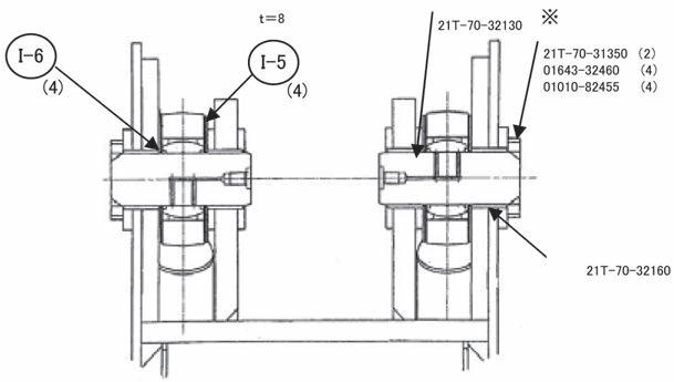

203 Assembly\ procedure Connection of hoses between boom and armC-9 Precautions Tools required Equipment required 1.Take care not to catch the O-rings in the parts (Apply grease to them before 2.Afterinstalling).connecting the hoses, bleed air from the bucket cylinder securely. 3.When the oil stopper is removed, oil spouts out. Take care. Name Q’ty Name Q’ty 22 mm Socket 1 27 mm Socket 1 200 mm Extension 1 Air Impact wrench 1 Others #20Hose O-ring Flange cylinderonside Washer on cylinder side Bolt cylinderon side #14Hose O-ring Flange cylinderonside Washer on cylinder side Bolt cylinderon No.Partside No.Parts I-1607000-B3048O-ring4I-1521T-64-41870Hose2I-1407084-C1427Hose2I-1307371-52080Flange4I-1207371-51470Flange4nameQ'tyNo.Part No.Parts I-2101010-81865Bolt8I-2001010-81455Bolt8I-1901643-31845Washer8I-1801643-31445Washer8I-1707000-B2060O-ring4nameQ'ty Remove the oil stoppers from the boom piping (tubes) and bucket cylinder piping, and then install the 4 hoses as shown in the following Connectingfigure.parts: 8 places marked with ※ Use the split flanges, bolts, etc. used to install the oil stoppers on the tube side as they Partsare.toinstall oil stoppers (on tube side) #20 07371-52080Hose (Flange) × 4 pcs.:Reuse 01010-81865 (Bolt) × 8 pcs.:Reuse 01643-31845 (Washer) × 8 pcs.:Reuse 07000-B2060 (O-ring) × 2 pcs.:Keep 07378-12010 (Head) × 2 pcs.:Keep #14 07371-51470Hose (Flange) × 4 pcs.:Reuse 01010-81455 (Bolt) × 8 pcs.:Reuse 01643-31445 (Washer) × 8 pcs.:Reuse 07000-B3048 (O-ring) × 2 pcs.:Keep 07378-11410 (Head) × 2 pcs.:Keep
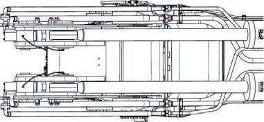
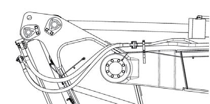
204 Connection between chassis and boom (Connecting parts of revolving frame and boom seen from rear upper direction of machine) Connection between boom and arm (Connecting parts of boom and arm seen from right of machine) Assembly procedure Connection of auto grease pipingC-10 Precautions Tools required Equipment required •Grease pipings can be installed before the connection of the arm. Name Q’ty Name Q’ty 30 mm Spanner 1 32 mm Spanner 1 Others Remove the oil stopping parts marked with ※ and connect the hoses and T-pieces. Oil stopping parts Hose 07376-50422side (Plug) T-piece 07222-00414side (Plug) 07221-20422 (Nut) No.Part No.Parts I-2907631-20409Hose1I-2801024-81225Bolt2I-2721T-70-32330-NKBracket1I-2601024-81055Bolt6I-2521T-04-31620-NKPlate3I-24203-973-5720-NKSeat3I-23203-973-5660-NKClamp3I-2221T-68-31830-NKTube1nameQ'tyRemovetheoilstoppingpartsmarkedwith A and connect the hoses and T-pieces (2 places). Oil stopping parts Boom side 07376-50422Arm07221-2042207222-00414(Nipple)(Plug)(Nut)side(Hoes)(Plug)


205 Assembly procedure Connection of wiring between boom and chassisC-11 Precautions Tools required Equipment required Name Q’ty Name Q’ty Others No.Part No.Parts nameQ'ty I-30 04434-51712Clip2 I-31 01024-81220Bolt2 Air impact wrench 111Extension L200 Socket 19 mm in width across flats X X 30 31 (1)Remove the connector plug. (2)Clamp the wiring harness on the side of the cab base. (2 places) (3)Pass the wiring harness through the hole on the side of the cab base and connect it to connector CN-A13 in the cab base. (Refer to the procedure A-17.) Wiring harness clamp (Side of cab base)
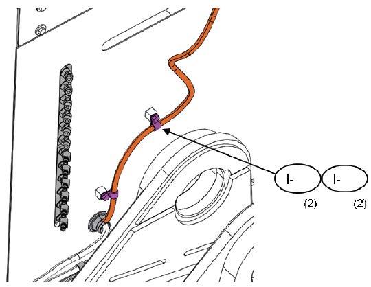
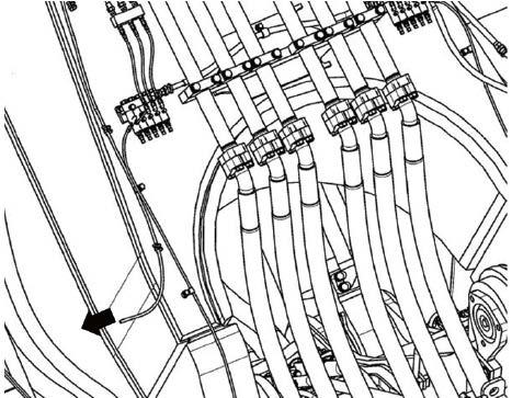
206 Assembly procedure Installation of bucket assembly (1/3)C-12 Precautions Tools required Equipment required 1.Bushings are press fitted to the arm assembly and bucket assembly. 2.Put a block under the bucket to prevent the latter from falling back down. Name Q’ty Name Q’ty Hammer 1 ø20, 5 m Wire 2 19 mm Socket 1 55 mm Socket 1 10 mm Spanner 2 10 mm Hexagonal wrench1 45 t Crane 1 Air Impact wrench 1 Others 45 t Crane 20 × 5 m Wire × 2 pcs. Wooden block (1)Install[Procedure]the wire to the bucket assembly as shown in the figure and place it on a level (2)Cleanground.the pin and the inside of the bushing. (3)Coupling with arm 1)Align the holes by operating the boom and 2)Installarm.the pins. 3)Adjust the shims. 4)Install the covers. 5)Supply grease.
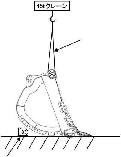

207 Detail of arm and bucket connecting pins Assembly procedure Installation of bucket assembly (2/3)C-12 Precautions Tools required Equipment required 1.Take care of the seals and O-rings. 2.Before inserting each pin, apply grease to the pin hole (inside of the bushing). 3.Tightening torque of elbow (J-6): 19.6 – 39.2 Nm {2.0 – 4.0 kgm} Name Q’ty Name Q’ty Others J-8 J-1 Pin (bucketSeal side) O-ring: See following figure. Stamp: L.H. Stamp: R.H. •Stamps on pin covers LH: For lefthand RH: For righthand Bushing, press fitted already Bushing, press fitted already Bushing, press fitted already Nut Washer O-ringBolt O-ring section No.Part No.Parts J-1601643-33690Washer12J-1501010-83685Bolt12J-1407000-15175O-ring2J-1321T-70-34341-NKCover2J-1221T-70-33171Pin2J-1001010-83695Bolt12J-907000-15195O-ring2J-821T-70-34333-NKCover2J-707000-12011O-ring2J-621T-62-34220Elbow2J-501596-00606Nut4J-401640-20610Washer8J-3205-09-61240Bolt4J-2209-70-71370O-ring4J-1209-72-11261Seal4nameQ'tyJ-1101643-33690Washer12 Fit of pin and arm bushing --- Clearance: 0.382 – 0.527 mm Fit of pin and bucket bushing (outside) --- Clearance: 0.255 – 0.390 mm Fit of pin and bucket bushing (inside) --- Clearance: 0.293 – 0.419 mm M6 × 1 piece, width across flats 10 mm
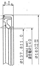
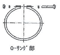
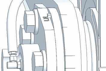
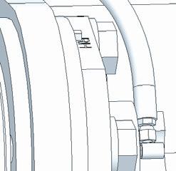
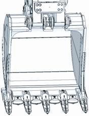
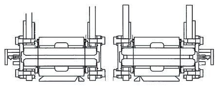
208 (1)Remove[Procedure] the right and left covers. (2)Connect the hoses. 3 Tightening torque of hose: 19.6 – 39.2 Nm {2.0 – 4.0 kgm} (3)Install the right and left covers. Be careful not to catch the hose. Assembly procedure Installation of bucket assembly (3/3)C-12 Hose Cover Cover a Be careful not to catch the hose.

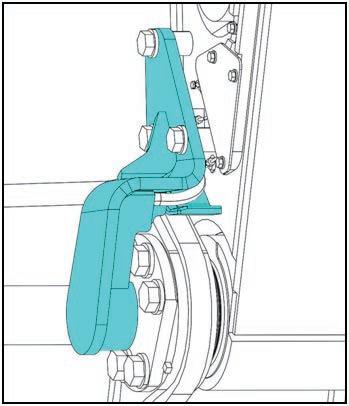
Connection of bucket link connection parts. the holes by operating the bucket. If the arm angle is as shown in the left figure below, you must press the link strongly in the direction of the arrow and cannot assemble easily. Take care. the pins. the covers. (5)Supply grease. air has not been bled from the bucket cylinder, limit the engine speed to low idle and do not move the cylinder to the stroke end. the arm angle carefully so that you can work easily. bushing is press fitted to the link the bucket cylinder, set the engine speed slow and operate the lever cylinder is moved to near either stroke end while the bucket is not installed, the grease hose will be broken. a Take care when bleeding air from the bucket cylinder. mm Press Bucket connectinglink pin
(3)Install
(1)Clean[Procedure]the
5.Ifcarefully.thebucket
Name Q’ty Name Q’ty Hammer (large) 1 24
3.A
Socket 1 200 mm Extension 1 ø12, 5 m Wire 1 45t Crane 1 Air Impact wrench 1 Others
a
(4)Install
209
Assembly procedure Installation of bucket link (1/2)C-13 Precautions Tools required Equipment required 1.Since
(2)Align
2.Set
4.Whenassembly.moving
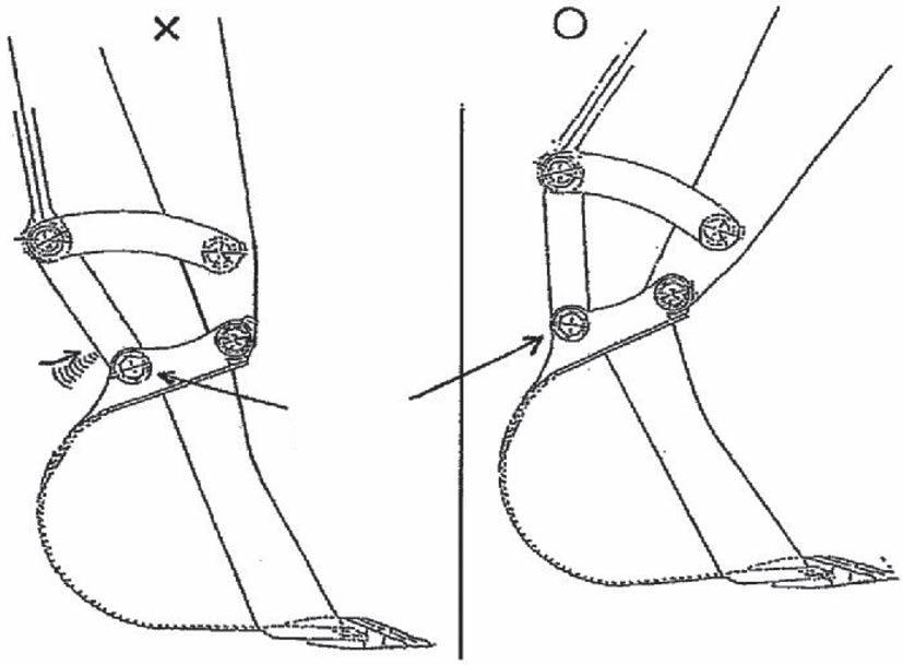
210 Bucket link connecting pin Assembly procedure Installation of bucket link (2/2)C-13 Precautions Tools required Equipment required 1.Take care of the seals. 2.Before inserting the pin, apply grease to the inside of the bushing. Name Q’ty Name Q’tyShimOtherst1.0(hasBushingbeen press fitted) Adjust clearance to 1 mm or less. Pin Shim (J-22) No.Part No.Parts J-2221N-72-11230Shim2J-2101643-31645Washer6J-2001010-81645Bolt6J-1921T-72-73170-NKStopper2J-1821T-70-33250-NKPin2nameQ'ty Clearance between pin and link bushing: 0.363 – 0.507 mm Clearance between pin and bucket: 0.043 – 0.306 mm
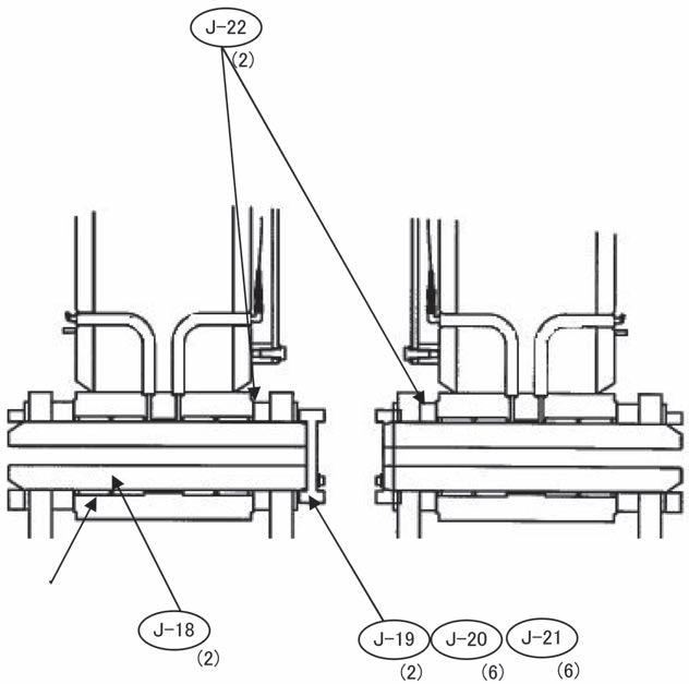
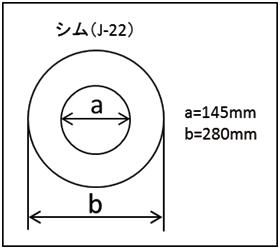

a
(5)Extend and retract each cylinder slowly 4 to 5 times. (Stop the cylinder approximately 100 mm before each stroke end and avoid relief.)
(1)Connect air bleeding vinyl hoses to air bleeders (1), (2), and (3).
Repeat (5) and (6) above until clean oil flows out.
(6)While running the engine at low idle, slowly extend and retract each cylinder to each stroke end once.
(3)Loosen air bleeders (1), (2), and (3) 4 turns.
(7)When clean oil flows out of air bleeders (1), (2), and (3), tighten air bleeders (1), (2), and (3).
211 Assembly procedure Bleeding air from cylinders (1/4)C-14 Precautions Tools required Equipment required
(4)Run the engine at low idle.
After bleeding air from each cylinder, retract the cylinder rod to the stroke end and check the sight gauge of hydraulic tank. If the oil level is below L, add hydraulic oil into the oil filler port.
a Before operating the cylinder, check that the flushing filter is installed. (To collect dirt in the circuit) Name Q’ty Name Q’ty Others Vinyl hoses
Perform the following procedure after assembling piping to each cylinder.
a If the engine speed is increased high or the cylinder is operated to the stroke end from the first, the air in the cylinders may damage the piston packings, etc.
a Since much air is in the circuit at the first operation, the cylinder may not operate for 10 seconds or more, but do not move the lever to the stroke end.
(2)Prepare oil containers at the vinyl hose ends.
Bleed air from work equipment circuit

At the first operation, the cylinder does not move for more than 10 seconds since much air is in the circuit. Do not move the control lever to the stroke end, however.
(1)Before installing the boom, set the boom cylinder in the horizontal position and perform following steps (2) and (3).
Bleeding air from boom cylinder
a After starting the engine, warm it up sufficiently to fit all the parts.
Assembly procedure Bleeding air from cylinders (2/4)C-14 Precautions Tools required Equipment required Name Q’ty Name Q’ty Others
(5)Keep the engine speed similarly to (3) for 1 minute.
Accordingly, perform the following air bleeding operation after assembling the boom cylinder.
(6)Bleed air from boom, arm and bucket cylinders immediately after installing each of them.
a
(2)While running the engine at low idle, extend and retract the boom cylinder 5 – 6 times, stopping it at about 100 – 200 mm before each stroke end.
(3)Extend the boom cylinder to the stroke end and keep the boom control lever at the stroke end for 3 minutes.
212
a Do not set the engine speed high or move the cylinder to a stroke end from the first. (Air in the cylinder may damage the piston packing etc.)
(4)After installing the boom, perform above steps (2) and (3).
When assembling the boom, you must align the boom cylinder top pin holes by extending or retracting the boom cylinder.
(2)Run the engine at full throttle and perform step (1).
(1)While running the engine at low idle, extend and retract the arm cylinder 5 - 6 times, stopping it at about 100 - 200 mm before each stroke end.
a Do not move the cylinder to the stroke end.
a After starting the engine, warm it up sufficiently to fit all the parts.
a Do not set the engine speed high or move the cylinder to a stroke end from the first. (Air in the cylinder may damage the piston packing etc.)
Assembly procedure Bleeding air from cylinders (3/4)C-14 Precautions Tools required Equipment required Name Q’ty Name Q’ty Others
Bleeding air from arm cylinder (Carry out this operation before installing the bucket)
After assembling the arm and arm cylinder, bleed air from the arm cylinder according to the following procedure.
213

Bleeding air from bucket cylinder
Precautions Tools required Equipment required
After assembling the bucket, bleed air from the bucket cylinder according to the following procedure.
(2)Run the engine at full throttle and perform step (1). a Do not move the cylinder to the stroke end. a Do not set the engine speed high or move the cylinder to a stroke end from the first. (Air in the cylinder may damage the piston packing etc.) a After starting the engine, warm it up sufficiently to fit all the parts.
Name
(4/4)C-14
Bleed air with the bucket installed. If the bucket cylinder is moved to near either stroke end while the bucket is not installed, the auto-grease hose will be broken. Q’ty Name Q’ty Others
Assembly procedure Bleeding
214
(1)While running the engine at low idle, extend and retract the bucket cylinder 5 - 6 times, stopping it at about 100 - 200 mm before each stroke end.
(3)After bleeding air, add hydraulic oil to the specified level. air from cylinders
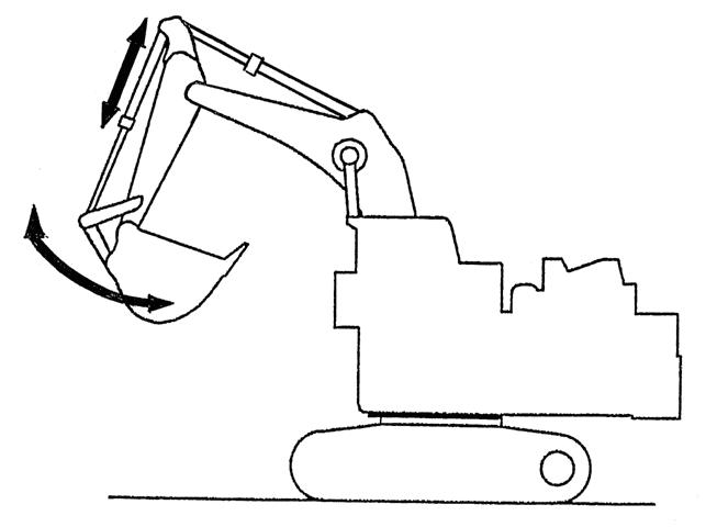
215 After assembling the large-sized hydraulic excavator in the field, touch up the following parts. When the machine is used on the seashore etc. where it is rusted easily, touch up the following parts, too. Unpainted parts of machined surfaces of flanges after installing piping Grease tubes Metallic hose bands, etc. Use rust-preventive clear paint for touching up the machined surfaces etc. (Recommended brand: KOMATSU genuine rust-preventive clear paint) Assembly procedure Parts to be touched up after field assembly (work equipment side)C-15 Precautions Tools required Equipment required Name Q’ty Name Q’ty Touch-up paint Rust-preventiveSandBrushpaper clear paint Others (1)Front and rear underside of boom (2)Underside of arm (3)Underside of bucket

216 •After assembling the whole machine, bleed air from the grease circuit according to the following procedure. (1)Remove the 3 plugs (581-96-19590, marked with a) from the injector assembly manifold one by one from the one nearest to the pump. Then, operate the auto grease unit continuously in the manual mode and check that pressurized grease comes out. After checking, install the plugs again. Order of check: Revolving frame front face ➞ Boom top face ➞ Arm top face (2)Supply grease with the grease gun through the service nipple of the injector and check that grease comes out of each greasing point. Assembly procedure Bleeding air from auto grease circuit (1/3)C-16 Precautions Tools required Equipment required A Do not use molybdenum disulfide grease to the bearings of the swing circle etc. Bushing:Molybdenum disulfide grease may be used. Bearing:Use lithium grease. Name Q’ty Name Q’ty Others Discharge adjustment screw Locknut 3 Tightening torque : 19.6 -- 24.5 Nm {2.0 -- 2.5 kgm} 3 Tightening torque : Plug (581-96-19590)19.6--29.4Nm {2.0 -- 3.0 kgm} Manifold Injector assembly Indicator pin Service nipple Tightening torque of cover : 18 Nm {1.84 kgm}

217 Assembly procedure Bleeding air from auto grease circuit (2/3)C-16 Boom cylinder bottom, right Circle Boom cylinder bottom, left Plug (581-96-19590) 3 Tightening torque : 19.6 -- 29.4 Nm {2.0 -- 3.0 kgm} Revolving frame frontArmfacecylinder bottom, right Boom top, right Boom cylinder head, right Boom foot, right Boom foot, right Boom cylinder head, right Boom top, right Arm cylinder bottom, right Plug (581-96-19590) 3 Tightening torque : 19.6 -- 29.4 Nm {2.0 -- 3.0 kgm} Boom top face


218 Assembly procedure Bleeding air from auto grease circuit (3/3)C-16 Arm B boss, right Arm A boss, right Bucket, right Bucket cylinder head, right Bucket cylinder head, left Bucket, left Arm A boss, left Arm B boss, left Bucket cylinder bottom, right Arm cylinder head, right Arm cylinder head, left Bucket cylinder bottom, left Arm C boss When adjusting injector, remove piping cover. After adjusting, install again. Front link + Bucket, left Front link + Wrist link, left Front link + Wrist link, left Front link + Bucket, right Front link + Wrist link, right Front link + Wrist link, right Plug (581-96-19590) 3 Tightening torque : 19.6 -- 29.4 Nm {2.0 -- 3.0 kgm} Arm top face

219 M.INSPECTION AND SERVICING PROCEDURES AFTER ASSEMBLY
220 Assembly procedure Inspection of oil levels and coolant levels and using standard of fuel and lubricant (1/2)M-1 * For details ofthe notes (Note. 1, 2, 3, 4) in the table, see the Operation and Maintenance Manual. The details refer to an Operation and Maintenance Manual about Recommended Komatsu fluids again. Hydraulic oil Hyper grease Hydraulic system Lithium grease Grease fitting EN590 Class2-3020 EN590 Grade D-1050 Fuel tank Diesel fuel G2-TE (KES)-2050 G2-LI (KES) Cooling system Non-Amine Engine coolant AF-NAC (Note. 4) AF-NAC (KES)-4050-2050G2-LI-S (KES)-3050 TO30 (KES) Fluid type TO10 (KES)-3010 Power train oil 0 40 EO10W30-LA(KES) -1550-2040EO15W40-LA(KES) Reservoir (KES)EOS5W30-LA(note.1) -2535 (KES)EOS5W40-LA(note.1) AmbientMin-2540MaxtemperaturedegreesCelsius( ℃)RecommendedKomatsuFluids Engine oilEngine oil pan PTO case Power train oil -2050 Power train oil TO10 HO46-HM(KES)-3050(KES) Swing machinery case Final drive case HO56-HE (KES)-3050 TO30 (KES)-3050
221 Assembly procedure Inspection of oil levels and coolant levels and using standard of fuel and lubricant (2/2)M-1 Engine oil pan PTO case machinerySwingcase(Each) Final(Each)casedrive oilHydraulicsystem Fuel tank Coolingsystem Grease Specifiedcapacity USLiter13840308524003400239200gal36.4610.577.9322.46634.13898.3463.1552.84 capacityRefill USLiter1284030851300--200gal33.8210.577.9322.46343.48--52.84 Min.temperatureatmospheric °CAbove-10-15-20-25-30-35-40°FAbove145-4-13-22-31-40 Amount of antifreeze USLiter71.78698109.9119.5129.1138.6gal18.9422.7325.8929.0531.5734.1036.63 Amount of water USLiter167.3153141129.1119.5109.9100.4gal44.2040.4137.2634.1031.5729.0526.52 Volume ratio (%)30364146505458
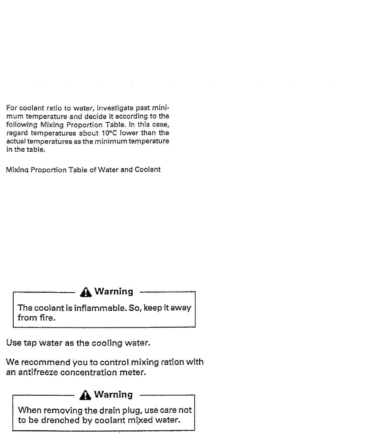
222 Assembly procedure Flushing of hydraulic circuit (1/9)M-2 Precautions Tools required Equipment required a Store and protect removed standard element (21M-60-51250), strainer (20Y 60-31140), and bypass valve assembly from dirt and breakage since they are used again after flushing. a Replace before starting assembly. (To collect dirt when connecting the hoses and dirt in the work equipment circuit) Name Q’ty Name Q’ty Small impact wrench 1 Socket 19 mm in width across flats1 Others 1.Replace return filter (Replace standard filter with flushing filter) Replace the standard hydraulic oil return filter element, bypass valve sensor assembly, and strainer with flushing element (1)and plate (2). a When replacing the element, raise it slowly so that dirt sticking to it does not fall in. Remove dirt left in the case with the hand. Flushing filter Standard filter Bypass valve sensor 20Y-60-31140Strainerassembly(3) Standardreturnfilter 21M-60-51250 (3)flushingbeforeReplace Special element for flushing Absolute filtration rating: 6 μ No.Loose-supply itemParts nameQ'ty K-1 21N-60-51220Cover3 K-2 569-33-72140Joint3 K-3 566-32-11620Cap3 K-4 566-32-11430Bleeder3 K-5 07000-B5180O-ring3 K-6 07002-61223O-ring3 K-7 07069-34057Spring3 K-8 22U-60-21380Plate3 K-9 NoInstalled209-60-77551Element3tochassisPartsnameQ'ty K-10 01024-81235Bolt12 K-K- K- KK- KK-K-KK-
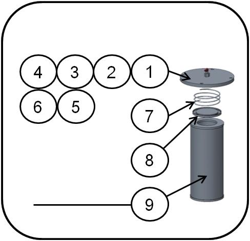
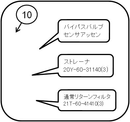
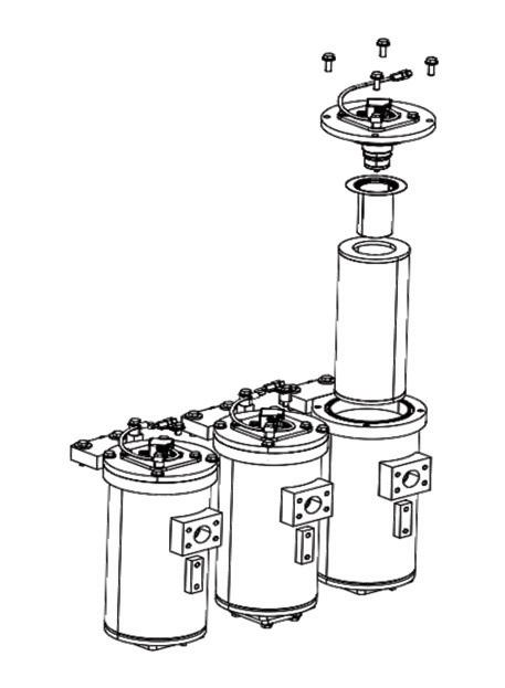


223 Assembly procedure Flushing of hydraulic circuit (2/9)M-2 Precautions Tools required Equipment required Name Q’ty Name Q’ty Others Fig. 1 Good state Fig. 2 Bad state a Do not install the element with its bottom on the elevated part of the case bottom as shown in Fig. 2. When the filter case is filled with oil, it is difficult to check if the element is inserted correctly. Turn the element by hand after inserting it in the case. When it turns smoothly, judge that it is inserted correctly. Installed state of element
2.Bleed air from work equipment circuit
(2)Prepare
(3)Loosen
a Before operating the cylinder, check that the flushing filter is installed. (To collect dirt in the circuit) Name Q’ty Name Q’ty Others Vinyl hoses
(4)Run the engine at low idle. and retract each cylinder slowly 4 to 5 times.
224 Assembly procedure Flushing of hydraulic circuit (3/9)M-2 Precautions Tools required Equipment required
(6)While running the engine at low idle, slowly extend and retract each cylinder to each stroke end once.
a If the engine speed is increased high or the cylinder is operated to the stroke end from the first, the air in the cylinders may damage the piston packings, etc.
(1)Connect air bleeding vinyl hoses to air bleeders (1), (2), and (3). oil containers at the vinyl hose ends. air bleeders (1), (2), and (3) 4 turns.
(Stop the cylinder approximately 100 mm before each stroke end and avoid relief.)
a After bleeding air from each cylinder, retract the cylinder rod to the stroke end and check the sight gauge of hydraulic tank. If the oil level is below L, add hydraulic oil into the oil filler port.
Perform the following procedure after assembling piping to each cylinder.
(5)Extend
Repeat (5) and (6) above until clean oil flows out.
(7)When clean oil flows out of air bleeders (1), (2), and (3), tighten air bleeders (1), (2), and (3).
a Since much air is in the circuit at the first operation, the cylinder may not operate for 10 seconds or more, but do not move the lever to the stroke end.
225 Assembly procedure Flushing of hydraulic circuit (4/9)M-2 Precautions Tools required Equipment required If the levers are operated at high idle (with the throttle at Max.), the element may break since the filter relief valve is stopped. Name Q’ty Name Q’ty Others 3.Flush hydraulic circuit After assembling all the parts, flush the hydraulic circuit. a Run the engine at low idle (set the throttle to Min.) with the levers in neutral for 15 minutes, then perform the following (1)Flushprocedure.workequipment piping Extend and retract each cylinder to just before each stroke end for several minutes. (a)Extend and retract bucket cylinder 5 (b)Extendmin. and retract arm cylinder 5 (c)Extendmin. and retract boom cylinder 5 min. Bucket operatio Arm Boomoperationoperation
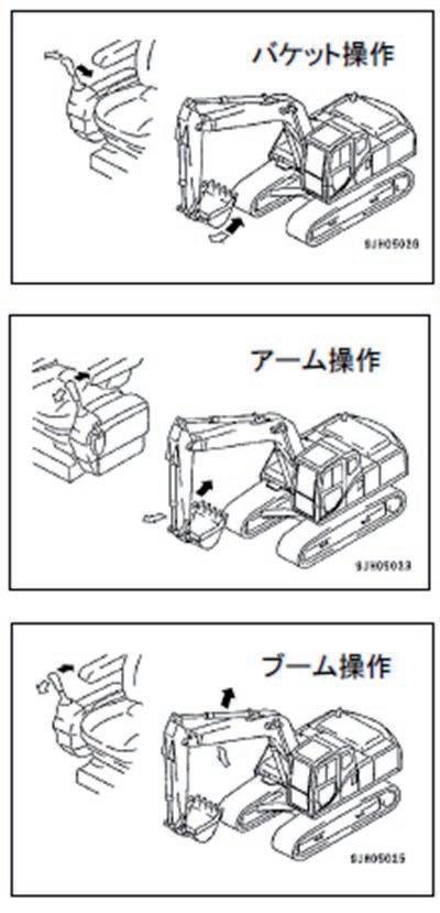
226 Assembly procedure Flushing of hydraulic circuit (5/9)M-2 Precautions Tools required Equipment required Name Q’ty Name Q’ty Others (2)Flush swing circuit Swing RIGHT } 3 min. eachSwing LEFT (3)Flush travel circuit Push the ground with the work equipment and raise either side of the machine as shown at right. Operate the travel lever as follows. Travel RIGHTForward } 3 min. eachReverse Travel LEFTForward } 3 min. eachReverse (4)CheckAfterflushing, replace the flushing filter with the standard filter according to "Replace return filter". At this time, check the dirt collected in the flushing element and see if it is problematic. If the dirt seems to be problematic, consult your Komatsu distributor. Swing operation
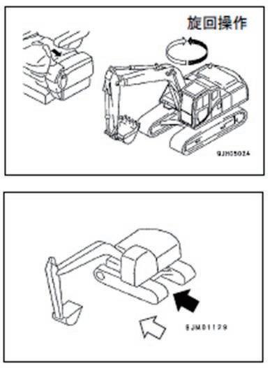
227 Assembly procedure Flushing of hydraulic circuit (6/9)M-2 Precautions Tools required Equipment required Name Q’ty Name Q’ty Small impact wrench 1 Socket 19 mm in width across flats1 Others 4.Replace return filter (Flushing filter → Standard filter) Reinstall removed standard hydraulic oil return filter element (1), strainer (2), and bypass valve sensor (3). a When replacing the element, raise it slowly so that dirt sticking to it does not fall in. Remove dirt left in the case with the hand. No.Item installed to machineParts nameQ'ty K-11 21M-60-51250 Element3 K-12 20Y-60-31140Strainer3-CoverA.3K-13 NoInstalled to chassisParts nameQ'ty K-14 01024-81235Bolt12 K-11K-13K-14K-12
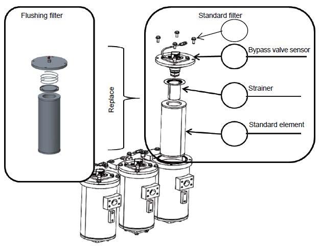
Installed state of element a Do not install the element with its bottom on the elevated part of the case bottom as shown in Fig. 2. When the filter case is filled with oil, it is difficult to check if the element is inserted correctly. Turn the element by hand after inserting it in the case. When it turns smoothly, judge that it is inserted correctly.
Fig. 1 Good state Fig. 2 Bad state
Check the used filter element according to "Inspection and maintenance procedure M??", then discard it. Discard according to local laws. The strainer, valve, and replaced plate are reusable. It is recommended to keep them for the next flushing. Name Q’ty Name Q’ty Others
228 Assembly procedure Flushing of hydraulic circuit (7/9)M-2 Precautions Tools required Equipment required
a
(3)Loosen air bleeders (1), (2), and (3) 4 turns.
(2)Prepare oil containers at the vinyl hose ends.
229
5.Bleed air from work equipment circuit (After flushing) After flushing, replace the return filter with the standard element, then bleed air.
(8/9)M-2 Precautions Tools
(1)Connect air bleeding vinyl hoses to air bleeders (1), (2), and (3).
a Since much air is in the circuit at the first operation, the cylinder may not operate for 10 seconds or more, but do not move the lever to the stroke end.
(6)While running the engine at low idle, slowly extend and retract each cylinder to each stroke end once.
Assembly procedure Flushing of hydraulic circuit required Equipment required
After finishing assembly, finally check the hydraulic tank oil level. For details, see Step M-XX "Check oil level in hydraulic tank and add oil" Name Q’ty Name Q’ty Others
(5)Extend and retract each cylinder slowly 4 to 5 times. (Stop the cylinder approximately 100 mm before each stroke end and avoid relief.)
(7)Repeat (5) and (6) above until clean oil flows out.
a After bleeding air from each cylinder, retract the cylinder rod to the stroke end and check the sight gauge of hydraulic tank. If the oil level is below L, add hydraulic oil into the oil filler port. Vinyl hoses
a If the engine speed is increased high or the cylinder is operated to the stroke end from the first, the air in the cylinders may damage the piston packings, etc.
(4)Run the engine at low idle.
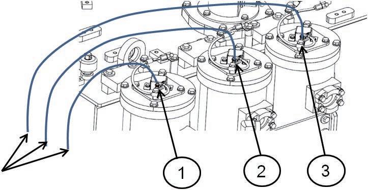
230 Assembly procedure Flushing of hydraulic circuit (9/9)M-2 Precautions Tools required Equipment required Name Q’ty Name Q’ty Others (8)Run the engine at high idle. (9)Slowly extend and retract each cylinder to each stroke end once. (10)When clean oil flows out of air bleeders (1), (2), and (3), tighten air bleeders (1), (2), and (3). Repeat (9) above until clean oil flows out. a After bleeding air from each cylinder, retract the cylinder rod to the stroke end and check the sight gauge of hydraulic tank. If the oil level is below L, add hydraulic oil into the oil filler port. Vinyl hoses
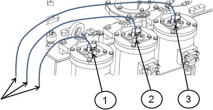
5.After
2.Remove
4.Operate
6.Set
Assembly
a
Precautions Tools required Equipment required Name Q’ty Name Q’ty Others FREELOCK
3.Run
Releasing
231
1.Set
When disconnecting the hydraulic piping, be sure to release the residual pressure according to the following procedure. the lock lever to the "FREE" position. the hydraulic tank cap. Loosen the oil filler cap of the hydraulic tank slowly to release the residual pressure, and then remove it. the engine for about 10 seconds, and then stop it. a Limit the engine speed to 1,000 rpm. a Keep the work equipment control levers in neutral. each work equipment control lever to the stroke end in 5 – 6 seconds after stopping the engine. Perform the operations in 3 – 4 above by 3 times. releasing the residual pressure, install the oil filler cap of the hydraulic tank. the lock lever to the "LOCK" position. procedure residual pressure from hydraulic circuitM-3
a
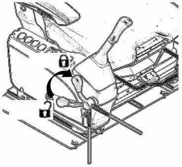
232 For check of the gas pressure in the HIC accumulator, see PC2000-11 Shop Manual, "Testing and adjusting". Assembly procedure Releasing residual pressure from HIC circuit and check of gas pressure in HIC accumulatorM-4 Precautions Tools required Equipment required Name Q’ty Name Q’ty Others
233 Assembly procedure Charging air conditioner with refrigerant (1/3)M-5 Precautions Tools required Equipment required If refrigerant gas gets in your eyes, you may lose your sight. Accordingly, when adding it, put on protective goggles. Gas must be collected and charged by a Forspecialist.details of refrigerant charging procedure, see the instruction manual for the tool kit. Be sure to observe the amount of air conditioner gas to be charged. If automatic charging machine is used, be sure to follow its operation manual to charge specified amount (front: 980 g, rear: 960 g) Name Q’ty Name Q’ty Others N2: Vacuum pump O: Gas leak detector N1: Service tool Using the tool kit in the following table, charge the air conditioner with gas. SymbolPart No. Part name Remarks N 1799-703-1200 Service tool kitFor HFC134a (R134a) 2 799-703-1100 Vacuum pump For HFC134a (R134a) (100 V) 799-703-1111 Vacuum pump For HFC134a (R134a) (220 V) 799-703-1121 Vacuum pump For HFC134a (R134a) (240 V) O799-703-1401Gas leak detector Approx. 30 min -100 kPa {-750 mmHg} or below Leave for 5 min There is pressure fluctuation (There is leakage) 1.Start vacuuming Stop sight4.Check3.Charge2.Checkvacuumingairtightnessrefrigerantthroughglass connectedCheck/Repairportions 5.Check gas leakage CONTROL PANEL A/C UNIT CONDENCER RECIEVER TANK COMPRESSER A B A B A B A B A B OPERATOR'S CAB. CONDENCER BOX ENGINE UNIT Charge the air conditioner gas according to the following procedure. For detail, see the next pages and after. a Since PC2000-11 is equipped with two air conditioners, charge them one by one, checking A and B shown in the figure. Type of air conditioner gas: HFC134a (R134a) Amount of charge:Front compressor (A): 980 ± 50 g Rear compressor (B): 960 ± 50 g Charge them with refrigerant in five each of 200g air conditioner gas can (20Y-979-3310) through the compressors of A and B. Use the air conditioner gas supplied loose from the plant. Do not use any other gas. However, it cannot be supplied loose in the EU district (for the machines of EU specification). Accordingly, prepare and use the same product locally.
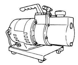
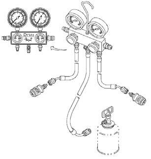

234
3.Charging of refrigerant
Refrigerant gas must be collected and added by a qualified person. For details of refrigerant charging procedure, see the instruction manual for the tool kit.
If the compressor is operated while the high pressure valve of the tool kit is open, the refrigerant flows back, and it is dangerous. If the refrigerant is charged from the low pressure side first, the compressor may be broken by liquid compression. Q’ty Others
Refrigerant charge work
3-3) To operate only the control panel corresponding to the compressor being charged with the gas, turn on only the air conditioner switch of panel A (left side) while A (front side) is being charged, and turn on only the air conditioner switch of panel B (right side) while B (rear side) is being charged. 3-4) While running the engine at low idle, charge the 800 g of the rest of the air conditioner gas (200 g x 4) from the low pressure
Charging air conditioner with refrigerant (2/3)M-5 Circuit Compressor Control panel Receiver tank AFront side of machineLeft side of machineLeft side of machine BRear side of machineRight side of machineRight side of machine
Assemblyside. procedure
3-2) Close the high pressure valve of the tool kit, and then start the engine.
Precautions Tools required Equipment required If refrigerant gas gets in your eyes, you may lose your sight. Accordingly, when adding it, put on protective goggles.
1.Using the vacuum pump, vacuum the refrigerant piping to -100 kPa {750 mmHg} or below. Air and moisture are removed from the refrigerant piping by vacuuming.
2.After vacuuming, leave for five minutes and check that the gauge pressure does not change. If the pressure has changed, air tightness is low. In this case, check the piping joints again and repair, and then perform the procedure again from 1.
ENGINE ASS'Y A Front compressor B Rear lowCharginghighCharginghighChargingcompressorvalveonpressuresideChargingvalveonlowpressuresidevalveonpressuresidevalveonpressureside A/C SWITCH No.Part No.Parts nameQ'ty E-55 20Y-979-3310Drum10 CONTROL PANEL OPERATOR'S CAB. A B
3-1) With the engine stopped, charge 200 g of the air conditioner gas (one can) from the high pressure side. (Never operate the air conditioner while no refrigerant gas is in it.)
Name Q’ty Name
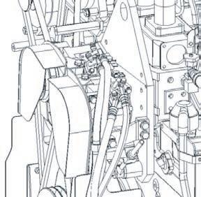

★
★
4.
235 Assembly procedure Charging air conditioner with refrigerant (3/3)M-5
Ambient temperature Ga uge pres s ure Refrigerant is insufficient Refrigerant is charged too much between ambient temperature and refrigerant pressure Check the amount of the charged air conditioner gas through the sight glass. Do not check the amount of the charged air conditioner gas by only the gauge pressure since it varies largely with the ambient temperature While running the engine at high idle, check theamount of charged refrigerant through the sight glass on the top of the receiver tank. If the amount is proper, few bubbles are seen through the sight glass while the air conditioner is operated If the refrigerant seems milky, the amount of ther efrigerant is insufficient In this case, check gas leakage, repair the leaking portion, and then charge the refrigerant again adding refrigerant while how much refrigerant ha sbeen charged is unknown, add until few bubbles are seen, and then add 200 g (one can) as spare, and the total amount is proper. while operating the air conditioner, check the piping joints for gas leakage with the detector Check gas leakage in a well ventilated place Apply the probe not at one point but all around the joint BA Inspection Sight glass
Precautions Tools required Equipment required Name Qʼty Name Qʼty Othe rs
★ When
Relationship
5.Finally,
★
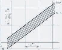
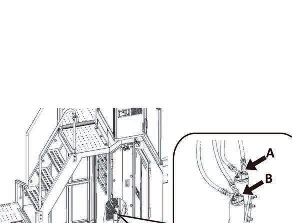
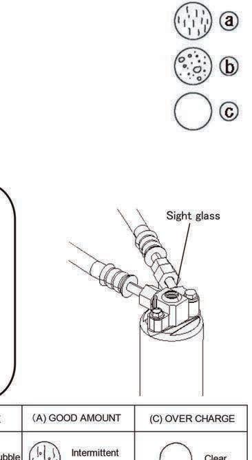
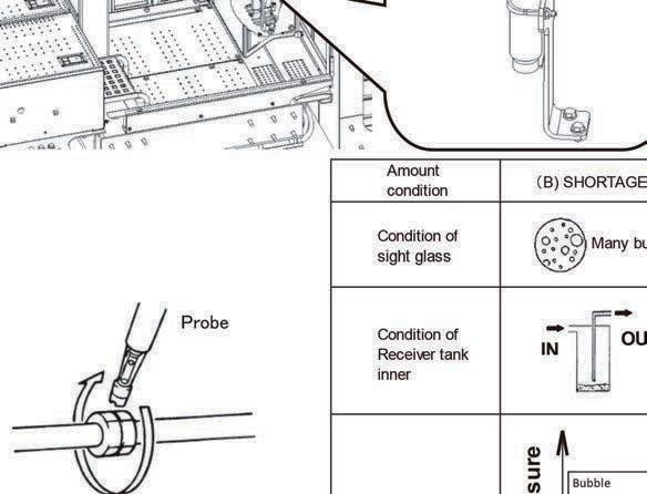
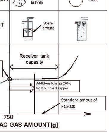


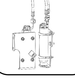

236 Assembly procedure Installed angles of mirrors (1/3)M-6 Precautions Tools required While sitting in the operator's seat and checking the visibility, adjust the angle of each mirror. Name Q’ty Name Q’ty Right step mirror Operator's cab mirror Left rear mirror Right Front Left step mirror <Right step mirror> (Loose-supply item) No.Part No.Parts nameQ'ty K-15 21T-53-31820-XCSupport1 K-16 21T-53-31791-XCBracket1 K-17 21T-53-33860-XCBracket1 K-18 21T-53-31841-XCBracket1 K-19 21T-53-31850-XCBracket1 K-20 07283-53444Seat10 K-21 07283-33450Clip10 K-22 01597-01009Nut24 K-23 01643-31032Washer24 K-24 07283-33442Clip2 K-25 20Y-54-61630-XCClamp1 K-26 01252-71025Bolt2 K-27 01010-81640Bolt2 K-28 21T-72-12620Washer1 K-29 01643-31645Washer1 K-30 23S-54-36270Mirror1 K-31 56B-54-17313Mirror ass’y1 K-20K-16K-21K-22K-23 K-26K-25K-15K-20K-21K-22K-23K-28K-27K-30K-31K-17K-29 K-20K-21K-23K-22K-18 K-23K-22K-24K-19 K-21K-23K-22K-20K-17 Air impact wrench 1 Socket 19 mm in width across flats 1 Socket 24 mm in width across flats 1 Socket 17 mm in width across flats 1 Extension L200 1 Hexagon socket 8 mm in width across flats 1
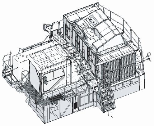

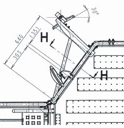

237 <Left rear mirror> (Sent individually) Assembly procedure Installed angles of mirrors (2/3)M-6 Precautions Tools required Equipment required While sitting in the operator's seat and checking the visibility, adjust the angle of each mirror. Name Q’ty Name Q’ty FrontLeft No.Part No.Parts nameQ'ty K-32 23S-54-36270Mirror2 K-33 21T-54-34690-XCSupport1 K-34 21T-54-79620-XCClamp2 K-35 01252-71025Bolt4 K-36 21T-54-34850-XCPlate1 K-37 21T-54-34680-XCPlate1 K-38 07283-32236Clip4 K-39 01643-31032Washer8 K-40 01597-01009Nut8 Air impact wrench 1 Socket 17 mm in width across flats 1 Extension L200 1 Hexagon socket 8 mm in width across flats 1 K-K-40K-3938K-36K-32K-K-40K-3938K-37K-33 K-32 K-34K-35
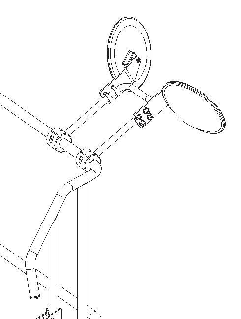
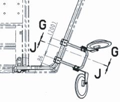
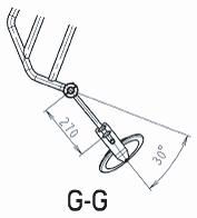
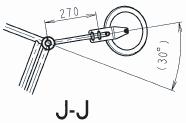
238 <Operator's cab left mirror> (Installed to side of operator's cab when machine is shipped) <Left step mirror> (Loose-supply item) Assembly procedure Installed angles of mirrors (3/3)M-6 Precautions Tools required Equipment required While sitting in the operator's seat and checking the visibility, adjust the angle of each mirror. Name Q’ty Name Q’ty No.Part No.Parts nameQ'ty K-41 2A5-54-13421Mirror1 K-42 2A5-54-16550-XCSupport1 K-43 20Y-54-61630-XCClamp1 K-44 01252-A1030Bolt2 Air impact wrench 1 Extension L200 1 Hexagon socket 8 mm in width across flats 1 K-44K-43K-42 K-41

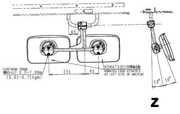
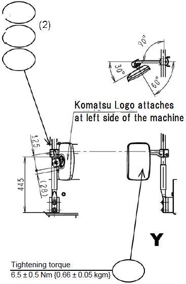
239 Assembly procedure Installed angles of lights (1/3)M-7 Precautions Tools required Equipment required While sitting in the operator's seat and checking the lighting direction, adjust the light angles. Name Q’ty Name Q’ty Others <Light above operator's cab> <Light above fuel tank>FrontFrontRightRight K-45K-46 (3) No. Part No. Q'ty K-45 21T-06-32810 1 K-46 22B-06-11690 3 Air impact wrench 1 Extension L200 1 Socket 22 mm in width across flats 1 Part name Work Lamp Ass`y Adjust angle of each working lights
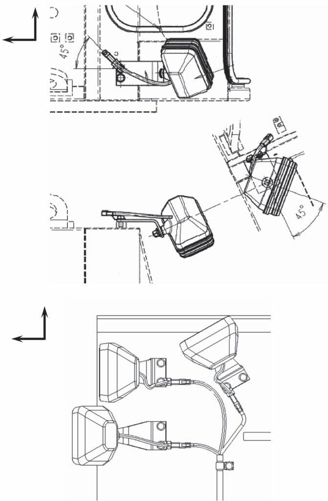
240 Assembly procedure Installed angles of lights (2/3)M-7 <Left step light> Bottom view of left step FrontLeft a For the part No. of the light, see A-13.
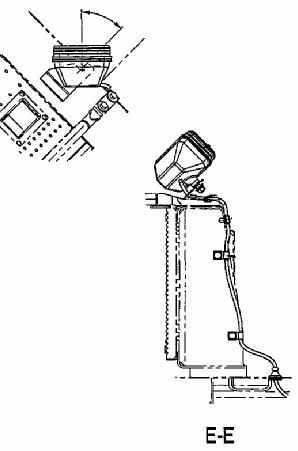


241 Assembly procedure Installed angles of lights (3/3)M-7 Precautions Tools required Equipment required Name Q’ty Name Q’ty Others Up Front Left side (Right side is similar) <Work equipment (Boom) light> Air impact wrench 1 Extension L200 1 Socket 22 mm in width across flats 1
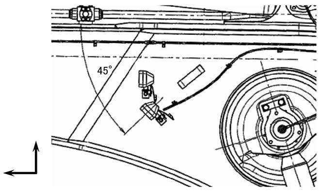
242 •Perform the following procedure when using KOMTRAX. •See the " Electrical system" of the chapter "Testing and adjusting " in PC2000-11 shop manual. •METHOD FOR STARTING UP KOMTRAX TERMINAL •DEFAULT SETTING OF KOMTRAX Plus CONTROLLER •DEFAULT SETTING OF WIRELESS LAN MODEM <Quoted from shop manual as a reference> Assembly procedure Method for starting up KOMTRAX terminal and default setting of KOMTRAX Plus controllerM-8


Equipment require AssemblyM-9Procedure ToolNameQ'tyrequirePrecautions NameQ'ty (1/13)Method of camera calibration for KomVision Others Calibration Flow 1.Calibration Sheet Spreading 1‐1:Required equipmentandworking space 1‐2:Sheet Spreading 2. Calibration procedure 2‐1:Calibration procedure(Auto) 2 2:Calibration procedure(Manual) 2‐3:Aujustplate in front of camera 2 & camera 3. 2-4:Adjust angle of other cameras. 3. Reference 3 1:CalibrationMarkerPoint(PC2000 11) 243
Calibration sheet ; See "Tool require" below 562-98-3A120 SHEET , Grid Front 562-98-3A130 SHEET, Grid Side 562-98-3A140 SHEET , Grid Rear 1 2 1 Q'tyPart No. Name Others Precautions Tool require Equipment require NameQ'ty (2/13) AssemblyM-9Procedure Method of camera calibration for KomVision 1.Calibration Sheet Spreading 1‐1:Required equipmentandworking space <Equipment> <Working space> 18m x 25m 1‐2:Sheet Spreading 1‐2‐1 At firstworking equipment is needed to be risen up to out of camera view. Reason is below, In order to spread Front Calibration sheet on the front of the machine. During calibration, in order to prevent that working equipment get into camera view. 18m 25m 244 If(Note)themachine has wide shoe(OPT:1010mm), it is necessary to rotate the upper swing structure clockwise by 5°. Reason is to see marker P5 on monitor.


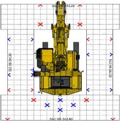
Precautions Others Name Equipment require Method of camera calibration for KomVision (3/13) NameQ'ty Q'ty AssemblyM-9Procedure Tool require 1 2 2 245 ※Place Part Number on rear side. 1 2 3. Spread the calibrationsheet (Rear), to fit the front edge of Rearsheet to “reference line”, and to fit center point of the Rear sheet to “b1 point”. Mark on the ground using the side edge of back surface on C/W (Point a1,a2) . Connect Point a1 and a2 and create reference line as right view. And mark on the ground on center of Rear Camera(Point b1)

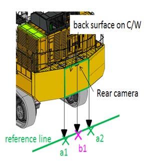
Others Precautions Tool require Equipment require NameQ'tyNameQ'ty Assembly Procedure Method of camera calibration for KomVision (4/13)M-9 1‐2‐4. Spread the calibrationsheet (Left& Right), and fold area shown as (★) of calibration sheet in the back. ※Place Part Number on out side. 1 2 5. Fit calibrationsheetsofleft& right 246 to the front edge of Rear sheet as below.
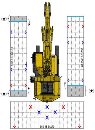
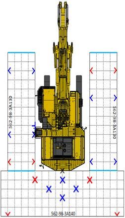
Others Precautions Tool require Equipment require NameQ'tyNameQ'ty Assembly Procedure Method of camera calibration for KomVision (5/13)M-9 1 2 6.Spread the calibrationsheet (Front), to fit the rear edge of Front sheet to front edge of Left and Right sheetas below. 247 ※Place Part Number on front side. If you have other calibretion sheet, it is necessary to make 16×23 grids as below. Please decide marker position according to 「3-1」.
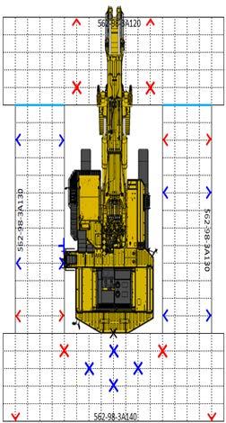

Others Precautions Tool require Equipment require NameQ'tyNameQ'ty Assembly Procedure Method of camera calibration for KomVision (6/13)M-9 2 Calibration procedure 2‐1:Calibrationprocedure(Automatic) KomVision Touch Panel Monitor a Push lower left corner on monitor. ・・・① b Push menu button. ・・・・・・・・・・・・・・② c.Push maintenance mode button. ・・・・・③ d.Push password input area. ・・・・・・・・・④ e Input Password and Push OK button. ・・⑤ f. Push OK button. ・・・・・・・・・・・・・・・・⑥ g.Push 7CAMERA CALIBRATION button. ・・⑦ h Push Automatic button. ・・・・・・・・・・・・⑧ i. ConfirmAutomatic calibration result.・・・⑨ j. Calibration result is "Failure" is displayed ⇒To (8/13) "Success" is displayed in all camera ⇒To(10/13) ① Hidden button ③ ② to Next Page 248
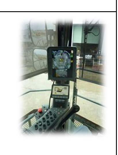

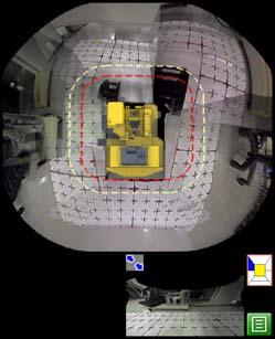
Result message Assembly Procedure Method of camera calibration for KomVision (7/13)M-9 Precautions Tool requireEquipment require Case Success Failure ⑨OthersNameQ'tyNameQ'ty Sentence Calculation Completed Successfully. Calculation Completed, But Large Error x.x pixels CAM* Calculation Failed. Recheck Marker Positions. ⑩Push Button NEXT MANUAL ④ ⑥ ⑤ Please push OK after password input. Password:6491 Confirm Automatic calibration result of 7 cameras in this window. If failure is displayed, perform manual calibration to readjust. (to next page) ⑦ ⑧ ⑨ ⑩ 249


Assembly Procedure Method of camera calibration for KomVision (8/13)M-9 Precautions Tool require Equipment require OthersNameQ'tyNameQ'ty 2 2:Calibrationprocedure(Manual) a. Pushthe manual button. ・・・⑩ b. Touch the vicinity of the marker you want to select in whole screen window.・・・⑪ c Magnification ratio change bar slid and the vicinity of marker is expanded.・・・⑫ d.Use enlarged screen window to select vicinity of the marker.・・・⑬ e.Push adjust button and adjust marker position.・・・⑭ f.Push decide button and decide marker position.・・・⑮ g.Use popup image and select marker .・・・⑯ h.Push OK button.・・・⑰ i. Perform manualcalibration in all cameras that failure sentense is displayed. j. Afterfinish all manual calibration, Push CALC button and confirm result window.・・・⑱ k. After success of all cameras calibration, push NEXTbutton.・・・⑲ l. Push END NEW SET TING button to save. next to BACK button to return regular screen . ・・・⑳ Repeat P●~P● (4 Points) Push NEXT button 250
In case of marker P1 for CAMERA1 Assembly Procedure Method of camera calibration for KomVision (9/13)M-9 Precautions Tool require Equipment require OthersNameQ'tyNameQ'ty ⑪ ⑬ ⑮ ⑩ ⑯ ⑰ Perform manual calibration in all cameras that failure sentens is displayed. Popup Image whole screen window ⑭ ⑫ ⑱ 251 enlarged screen window ratio change bar


Assembly Procedure Method of camera calibration for KomVision (10/13)M-9 Precautions Tool require Equipment require OthersNameQ'tyNameQ'ty ALL Success ⑲ ⑳ ⑳ 252
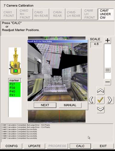


Assembly Procedure Method of camera calibration for KomVision (11/13)M-9 Precautions Tool require Equipment require Name Q'ty NameQ'ty Hexagonal wrench 6mm width across flats 1 Others CAM②CAM③ Adjustfront plate of Camera 2 & Camera 3 to show car body approx 5% in camera display. Reason for understanding car body side easily. 2 3.Adjust plate in front of camera 2 & camera 3. CAMERA ③ CAMERA ② front plate approx 5% Car bodyside <Before> <After> 253


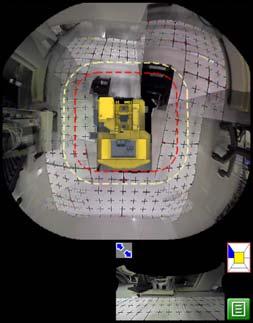

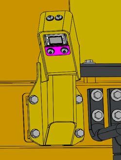
Assembly Procedure Method of camera calibration for KomVision (12/13)M-9 Precautions Tool require Equipment require Name Q'tyNameQ'ty Spanner 6mm in width across flats 1 254 2-4:Adjust angle of other cameras <Before> <After> Adjust angle of other cameras to show car body approx 5% in camera display. Reason for understanding car body side easily. Car body side Approx. 5% Hexagonal wrench 6mm 1 in width across flats Socket 19mm in width across flats 1 Socket 17mm in width across flats 1 Air impact wrench 1 <How to adjust angle of cameras> After adjusting cameras, tighten the bolts according to the procedure「A-63」. <How to access cameras>
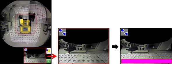
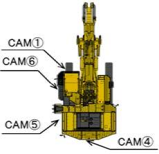

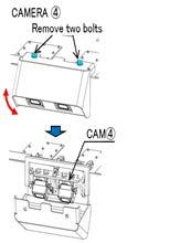
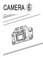
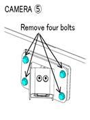
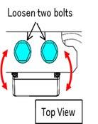
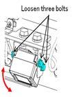
Assembly Procedure Method of camera calibration for KomVision (13/13)M-9 Precautions Tool require Equipment require OthersNameQ'tyNameQ'ty 3. Reference 3‐1:Calibration Marker Point(PC2000‐11) 255
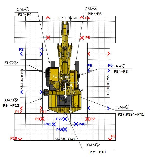
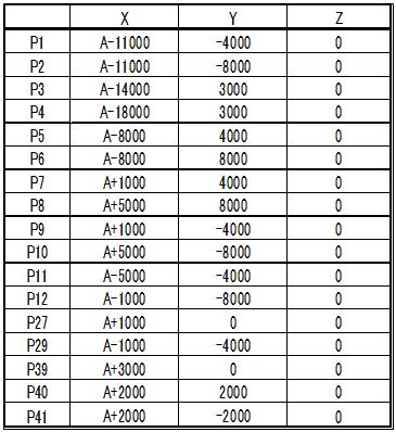
Check that oil flows out of main pump bleeders (1) and (2) Loosen suction tube plug (5) and check that oil flows out of it Crank for 15 sec twice Check that oil flows out of bleeder (2)
A-57 7/14Page Pilot valveLow
Low idle Raise and lower bucket 4 – 5 times (Stop at 100 mm before stroke end and do not relieve)
Main pump
Accordingly,
A-57Page5/14
Low idle Keep for 5 minutes
Loosen pump bleeders (1), (2) and (3) Add hydraulic oil to specified level
Low idle Start and stop swinging 5 – 6 times over Check that oil containing no bubble flows out of swing motor bleeder (11)
Low idle Raise and lower boom 4 – 5 times (Stop at 100 mm before stroke end and do not relieve)
Low idle Check that oil containing no bubble flows out of travel motor bleeder (12) idle Check that oil containing no bubble flows out of PPC bleeder (13) idle Check that oil containing no bubble flows out of PV1 and PV2 bleeders
the hydraulic pump assembly, pump EPC valve, or VC valve is removed and installed or the hydraulic oil is replaced, bleed air according to Field assembly manuals A-57 and C-14 and enter the contents of the bleeding work performed in this check sheet. (Make a copy of this page for the record.) the air is not bled at all or bled insufficiently, the pump may be broken. be sure to bleed air according to the given procedure. Operation Check time Checked by
(2)If
Start and run at low idle
Low idle Raise and lower arm 4 – 5 times (Stop at 100 mm before stroke end and do not relieve)
High idle Raise and lower boom 4 – 5 times (Stop at 100 mm before stroke end and do not relieve)
Check that oil flows out of fan pump bleeder (3)
High idle Raise and lower arm 4 – 5 times (Stop at 100 mm before stroke end and do not relieve)
C-14A-57 1/3Pages4/14Page–3/3 cylinderequipmentWork
Fan pump
Add hydraulic oil to specified level
Swing motor circuit
Low idleRelieve arm at stroke end
Date of check Serial JobsiteNo.
A-57Pages3/14–4/14
Low idleRelieve bucket at stroke end
Low idleRelieve boom at stroke end
High idle Raise and lower bucket 4 – 5 times (Stop at 100 mm before stroke end and do not relieve)
Raise work equipment from ground and swing upper structure 180° in opposite direction Loosen suction tube plug (5) and check that oil containing no bubble flows out Check that oil containing no bubble flows out of bleeders (1), (2) and (3) Stopped Remove hydraulic tank cap and add hydraulic oil to specified level
256 PC2000-11 Main pump air bleeding check sheet 1.Purpose(1)When
resultConsumed
Stopped
2.Air bleeding check Shop Manual Airportionbleeding Engine speed
Raise work equipment from ground and swing upper structure Loosen180°suction tube plug (5) and check that oil containing no bubble flows out
Start o
Travel motor circuit
Check that oil containing no bubble flows out of bleeders (1), (2) and (3) Tighten hydraulic tank cap
A-57 6/14Page PPC circuitLow
Backhoe specification1/13 Report No. FIELD ASSEMBLY INSPECTION REPORT After completion o f a ssembling a machine, make inspections according to these check sheets for assuring machine performance and quality. After the inspection, these check sheets must be submitted through EQP CARE system, or please send these check sheets to E-mail address below. Komatsu Osaka Plant ; [E-mail address] JP00MB_os_shaken@global.komatsu ModelPC2000-11,-11E0TypeBackhoespec. Machine serial No. User unit No. EngineSAA12V140E-7model Engine serial No. Service meter reading Date of inspection Attachment 1 ManufacturerModelSerialNo. 2 Location of machine at inspection Distributor's name Customer's name Address: DateName:: reportDeliveryNo. Inspector's Signature:Title:Inspector'scomments:name: KOMATSU USE ONLY: Check sheet receiving date: RemarkBy:: Check sheets filling instructions: 1. Use following indexes for entry of judgment. .......... Normal .......... Correction made on abnormal point .......... Abnormal .......... Not applied 2.Enter measured values in parentheses. [] (1)CriteriaNotes: area based on the standards when the machine is shipped out of the factory. (2)This FEIELD ASSEMBLY INSPECTION REPORT is for "A" specification.
Backhoe specification2/13 Category Revision Check item At assemblylocaltime At operating___hours Criterion assemblybeforeCheck Oil and coolant levels Measured value Coolant Soft water Radiator coolant []levelSub[]leveltankcoolant Radiator coolant level Sub tank coolant level (A,AntifreezeB,C,D, E) NotAdded/added [] pointFreezing [] A: -50 – -40 °C D:-20 – -10 °C B: -40 – -30 °C E:-10 – 0 °C C: -30 – -20 °C(Not necessary in summer) Engine oil E015W40-LAE010W30-LA [] L – H +5 (In 15 minutes after stopping engine) PTO oil T030T010 [] L +5 – H (In 15 minutes after stopping engine) Swing machinery case oil T030 [] L +5 – H +10 (In 15 minutes after stopping engine)T030 Final drive gear case oil T030[ ] 0 – -10 mm from level plug bottom T030[ ] Hydraulic oil HO56-HE[ ] Between H – L (Posture: Max. reach) Battery electrolyte [ ] Max. 13 mm from filler bottom Engine No. [ ] When acceptedAfter check Service meter[ h][ h] assemblyduringCheck Loosened or untightened connecting pin lock bolt Must not be detected. Loosened or untightened work equipment piping split flange Must not be detected. Uninstalled, lost or caught work equipment piping O-ring Must not be detected. Loosened or twisted grease piping joint Must not be detected. Shim adjustment for work equipment pin Max. 1 mm (For shim position, see assembly manual) Confirm the mounting direction of the boom cylinder Cylinder bottom side tube must be on the upper side. Improperly inserted or un-inserted wiring Must not be detected. Loosened or untightened ladder mounting bolt Must not be detected. Max. 25 mm RightFrontRearLeft
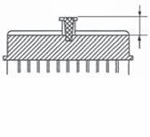
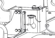

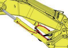
Backhoe specification3/13 Category Revision Check item At assemblylocaltime At operating___hours Criterion assemblyduringCheck Loosened or untightened counterweight mounting bolt Must not be detected. Clearance or level difference between counterweight and frame Max. 15 mm Loosened or untightened operator's cab mounting bolt Must not be detected. Loosened or untightened cab base mounting bolt Must not be detected. Loosened or untightened container base mounting bolt Must not be detected. Loosened or untightened hydraulic tank mounting bolt Must not be detected. Loosened or untightened fuel tank mounting bolt Must not be detected. Loosened or untightened center frame mounting bolt Must not be detected. Loosened or untightened travel system piping bolt/joint Must not be detected. Uninstalled, lost or caught travel system piping O-ring Must not be detected. Loosened or untightened track frame mounting bolt Must not be detected. Loosened or untightened travel motor cover bolt Must not be detected. Uninstalled part (Rearview mirror, etc.) Must not be detected. Bleeding air from hydraulic pump As per assembly manual Bleeding air from travel motor Bleeding air from swing holding brake circuit Bleeding air from work equipment cylinder circuit Bleeding air from HIC circuit Adjustment of track tension Flushing hydraulic circuit Greasing each part of work equipment Grease all parts. Check that grease comes out. Addition of hydraulic oil Add to between L – H. Addition of fuel and window washing fluid Fill tank. Check of charged air conditioner gas a Use the air conditioner gas supplied loose from the plant. Do not use any other gas. However, it cannot be supplied loose in the EU district (for the machines of EU specification). Accordingly, prepare and use the same product locally. Check that few bubbles are seen through sight glass on top of receiver tank while air conditioner is operated OverchargeoremptyGas amount is insufficient Proper

1. Check of monitor function When the starting switch is turned ON, all of the gauge section, check-before-starting section and monitor section must light up and alarm buzzer must sound.
Backhoe specification4/13
2. Check of gauge section and check-before-starting section
3. Check of monitor section After the engine is started, the caution lamps must not light up and the alarm buzzer must not sound in the range between low idle and high idle. Operation of service meter Service meter must be free from flaw, blur and uneven operation.
Display must be as shown on left.
Category Revision Check item At assemblylocaltime At operating___hours Criterion
monitorofCheck
All lamps must go off about 3 seconds after the starting switch is turned ON (all lamps are ON), then 2 seconds after, only the gauge section is displayed and the check-before-starting section and monitor section are kept OFF.
Initialization of KOMTRAX Plus Initialization must be executed. (Pm clinic, downloading, application for start of use).
MonitorMonitor
Monitor display
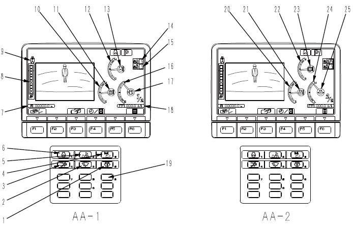
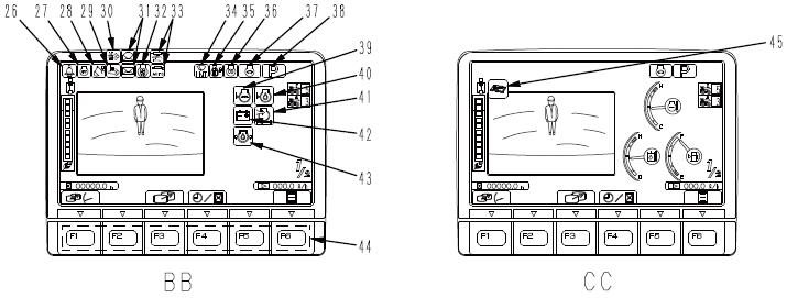

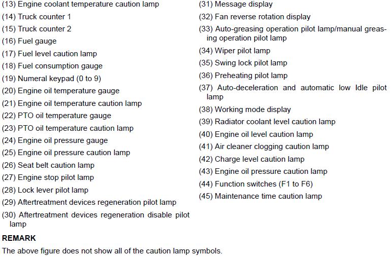
ON position (Operation): When swing operation is performed, machine does not swing. At this time, swing lock monitor lights up.
OFF position (Reset): Machine can swing. At this time, swing lock monitor goes off.
Backhoe specification5/13 Category Revision Check item At assemblylocaltime At operating___hours Criterion leversandswitchesofCheck
Operation of horn switch
Operation of hydraulic lock lever Lever down:LockEngine can be started. No work equipment moves. Lever up:UnlockEngine cannot be started. All work equipment moves.
If the switch is pressed, the horn sounds and flashlight (if equipped) at the front of the cab blinks for about 5 seconds.
Operation of swing lock switch
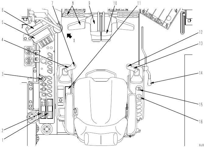
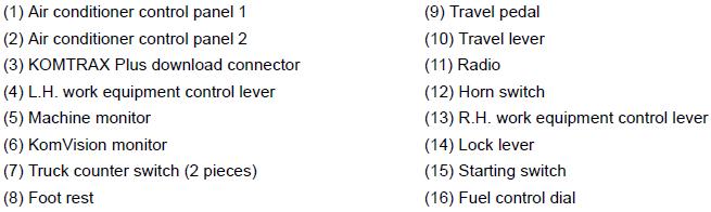
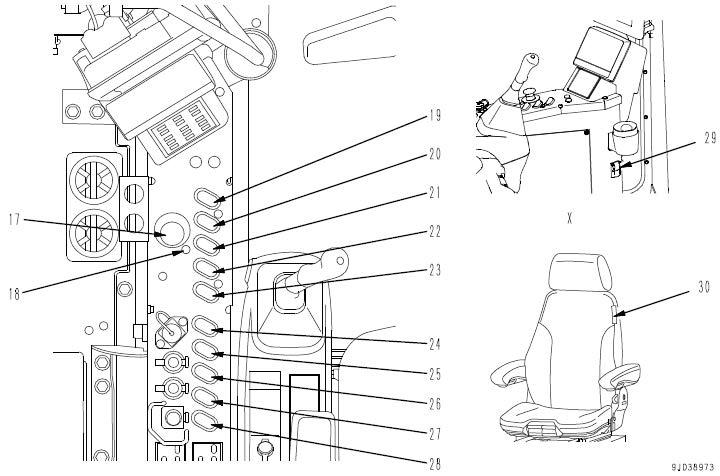

•Even if the starting switch is OFF, if the switch is pressed, the step light is turned ON for about 90 seconds.
Ladder must be raised and lowered smoothly. When ladder is lowered: Machine cannot swing and travel. Work equipment cannot operate. When ladder is raised: Machine can swing. Work equipment can operate.
Operation of room lamp switch
leversandswitchesofCheck
Switch is installed to front and rear of engine compartment and inside of operator’s cab (3 places in total), and left and right of power module (2 places if equipped)
Operation of heavy lift switch
ON position: Room lamp lights up.
Operation of power-assisted ladder
Operation of auxiliary lamp switch ON position: Auxiliary lamp lights up.
OFF position: Room lamp goes off.
OFF position: Auxiliary lamp goes off.
Operation of wiper switch
Operation of working lamp switch
OFF position: Working lamp goes off.
ON position: Rotary lamp lights up.
OFF position: Rotary lamp goes off.
Operation of emergency engine stop switch
Operation of greasing mode switch
MANUALGreaseposition:must be supplied manually.
Lighting of P: For heavy load work Lighting of E: For lower fuel consumption If the switch is operated, the monitor changes and the operator can select.
Operation of step light switch
Operation of machine push-up switch
Low pressure setting: Boom thrust force is low. High pressure setting: Boom thrust force is increased.
•If the switch is pressed, the step light is turned ON for about 90 seconds.
If the switch is pressed when the engine is started, engine must stop. While the engine is stopped in an emergency, caution lamp of monitor lights up.
Lighting of INT Intermittentlamp:operation of wiper Lighting of ON (Continuous) lamp: Continuous operation of wiper Lighting of ON (Continuous upper) lamp: Continuous operation of only upper wiper
Operation of boom shockless control switch If the switch is turned ON, work equipment shakes less when boom is stopped.
Category Revision Check item At assemblylocaltime At operating___hours Criterion
During single boom raise operation, if the switch is turned ON, the boom raise force is increased.
Operation of buzzer cancel switch If the switch is pressed, alarm buzzer for warning item is stopped.
Operation of rotary lamp switch
Lighting of P+: For much work volume
Each time the switch is pressed, the monitor changes and the operator can select.
Backhoe specification6/13
Operation of window washer switch If the switch is pressed, the window washing fluid spouts against the front glass. (Wiper operation is linked.)
AUTOGreaseposition:is supplied automatically.
Operation of working mode selector switch
Operation of auto-decelerator switch
ON position: Working lamp lights up.
Lamp ON: Auto-decelerator is operated. Lamp OFF: Auto-decelerator is reset. Each time the switch is pressed, the monitor changes and the operator can select.
Operation of air conditioner
Check of fault history (electrical system and mechanical system)
Operation of cigarette lighter If the lighter is pushed in, it is heated red and returns automatically several seconds after.
When the switch is turned ON, the air conditioner starts.
While the leve or pedal is operated, work equipment or machine moves with the lock lever released.
When normal: Switch is set "down". If the switch is set "up", the monitor caution lamp lights up.
When normal: Switch is set "down". If the switch is set "up", the alarm buzzer sounds and the monitor displays L03 error.
Operation of lock lever auto-lock release switch
Operation of service arm (if equipped) Service arm can be raised or lowered Whensmoothly.the service arm is lowered, work equipment or machine cannot move if the lever or pedal is operated. Monitor caution lamp lights up.
Auto-lock release function does not work with this switch “up”.
Category Revision Check item At assemblylocaltime At operating___hours Criterion leversandswitchesofCheck
Operation of radio When the switch is turned ON, the radio sounds.
Backhoe specification7/13
Operation of travel lever
If the switch (1 or 2) is pressed, the confirmation buzzer sounds and the monitor counts.
Operation of swing holding brake prolix switch
Operation of left work equipment control lever (With auto-deceleration function) This lever is used to operate the upper structure and arm. N (Neutral):Upper structure and arm are fixed.
When normal: Switch is set "down". If the switch is set "up", the monitor caution lamp blinks.
Operation of truck counter switch
Operation of emergency pump prolix switch
Forward:Lever is pushed forward. (Pedal is angled forward) Reverse:Lever is pushed back. (Pedal is angled back) N (Neutral):Machine stops.
Check that no abnormality is displayed and then delete the fault history. After finishing all the checks, check again that there is no fault history.
Operation can be continued with this switch set "up".
Brake can be released and machine can swing with this switch set "up". Swing brake is kept released, however.
Operation of right work equipment control lever (With auto-deceleration function) This lever is used to operate the boom and Nbucket.(Neutral):Boom and bucket are fixed.
Backhoe specification8/13 Category Revision Check item At assemblylocaltime At operating___hours Criterion performanceSwing Swing operation running in: Engine at high idle Right Left Normal swing speed[ sec][ sec] P+ mode: 12.0 – 13.0 sec/turn P mode: 12.8 – 14.0 sec/turn E mode: 12.8 – 14.0 sec/turn Brake angle Max. 55° (Sensory) Unevenness and hunting of swing Must not be detected. Abnormal sound and shakiness in swing Must not be detected. Travel performance Travel operation running in: Engine at high idle Abnormal sound and heating in track roller, carrier roller and idler Abnormal sound and heating must not be detected. Operation of travel brakeMust operate securely without dragging. Abnormal sound in travel and shakiness in swingMust not be detected. Travel deviation (Sensory) Must be free from abnormal travel deviation in the range from fine control to stroke end (Sensory). Travel deviation (To be measured only when abnormal) Max. 200 mm/20 m Track rotation speed Right 20.1 ± 2.0 sec/turn (P+ mode, full throttle) Left Track Grease(Elongation)HICStroketensionofcylindercylinder Empty(Work equipment posture: Max. reach) (Work equipment posture: Max. reach) Forward Reverse [] [] mm/20m mm/20m Forward Reverse [] [] sec sec Forward Reverse [] [] sec sec Right Left [] [] mm mm a Travel forward and in reverse on a flat ground and then stop slowly Right Left [] [] mm mm [] [] mm mm AB 135Stroke±5 mm
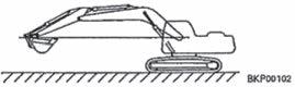


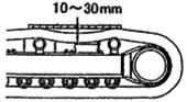
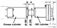
Backhoe specification9/13 Category Revision Check item At assemblylocaltime At operating___hours Criterion performanceequipmentWork Work equipment running in: Engine at high idle (Note: Lower boom cylinder to ground level) Pressurization: Relieve each port for 2 minutes and give shock 20 times (excluding boom lower operation). Work cushionspeedWorkP+postureequipmentmodeequipment(Includingworking time) P Engine:mode Full throttle 8.7 m boom 3.9 m arm 12 m3 bucket RaisesecLowersec Boom[][] Raise: 7.0 ± 0.7 sec Lower: 5.3 ± 0.5 sec In secOutsec Arm[ ][ ] In: 7.5 ± 0.8 sec Out: 5.0 ± 0.5 sec CurlsecDumpsec Bucket [][] Curl: 5.0 ± 0.5 sec Dump: 3.9 ± 0.4 sec Work equipment time Engine:lag Low When MeasureWhenSensorynormal:abnormal: Lower sec Boom[ ] Max. 6.0 sec In sec Arm[ ] Max. 5.0 sec Dump sec Bucket[ ] Max. 4.0 sec Abnormal sound from hydraulic pump and PTO Must be free from abnormality during no-load operation and when relieved. Heating of PTOMust be free from abnormal heating. Partial engine output performance Engine must not hunt in any gear speed during no-load operation and must not stall when hydraulic circuit is relieved at low idle. Fine control performance Work equipment must operate smoothly. Machine push-up operation (including machine push-up function) Boom, arm and bucket must not escape. Abnormal sound or creak from work equipment Must not be detected. Shock at cylinder stroke end (Shock at boom raise and arm in stroke ends) Cushion must work sufficiently. Function of accumulator Immediately after engine is stopped, with key switch ON, boom cylinder must be retracted from extension stroke end to ground level (when arm is at max. reach). BoomEmpty Empty Empty Arm Bucket
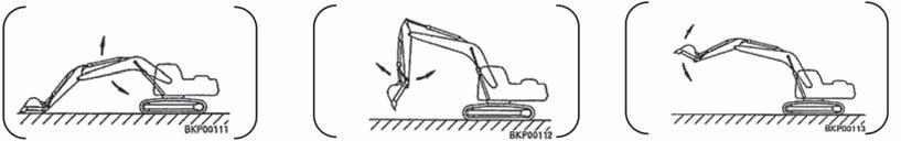
Backhoe specification10/13 Category Revision Check item At assemblylocaltime At operating___hours Criterion operationDuring Check of each part Operating effort of control lever when each actuator is operated • Lever must not be hitched during operation. • Lever must return to neutral by itself. Shaking and beat noise of operator's cabMust not be detected. Beat noise of frame, guard and ladderMust not be detected. seatoperator'sAround Movement of doors and windows Must move smoothly. Locks of doors and windows Must work securely. Adjustment of operator's seat All adjustment must be possible. Undercarriage Oil (Idler,leakagetrack roller, sprocket, final drive gear case, motor, brake valve) Must not be detected. Interference of each part Must not be detected. Looseness of track shoe bolt Must not be detected. Contact of link tread Must be free from overlapping, flaking and breakage. chassisAround Oil (Centerleakageswivel joint, pump, solenoid valve, relief valve, control valve, PPC valve, swing motor, brake valve, shuttle valve, swing machinery, hydraulic tank, piping) Must not be detected. Fuel (Fuelleakagetank,engine, piping) Must not be detected. Water leakage from engine cooling system Must not be detected. Oil leakage from engine lubrication system Must not be detected. Gas leakage from engine gas system Must not be detected. Operation of covers Must move smoothly. Locks of covers Must work securely.
Backhoe specification11/13 Category Revision Check item At assemblylocaltime At operating___hours Criterion chassisAround Operation of grease pump Must operate smoothly. Looseness and insufficient insertion of electric wiring terminalsMust not be detected. Electric wiring route Clearance of at least 10 mm must be made around moving part and edge. Air leakage from air system Must not be detected. Interference of each part Must not be detected. equipmentworkAround Oil (Cylinder,leakagepiping, block) Must not be detected. Grease leakage from grease piping Must not be detected. Interference of work equipment Must not be detected. Looseness of work equipment piping clamp and play of piping Must not be detected. Twist of hydraulic hose and operation of work equipment at reverse Must not be detected.
Backhoe specification12/13 Note: If the operation or function is defective, measure as necessary.The speeds in the criteria column are the values in P mode. Category Revision Check item At assemblylocaltime At operating___hours Criterion 1.Engine speed: Check in monitoring mode "01002". P+ mode Low idle [ rpm] 825 ± 50 rpm High idle [ rpm] 1980 ± 50 rpm Boom raise relieve speed (Heavy lift: OFF) [rpm] 1750 ± 50 rpm Boom raise relieve speed (Heavy lift: ON) [rpm] 1750 ± 50 rpm 2.Oil pressure measurement: Check in monitoring mode . 1F pump: "011001R pump: "01101" 2F pump: "011262R pump: "01127" Control valve main set pressure 2R[2F[1R[MPa]1F[MPa]MPa]MPa] 29.4 ± 1.0 MPa At engine high idle, boom raise, P+ mode, heavy lift OFF and relief Control valve main set pressure (Boosted pressure) 2R[MPa]2F[MPa]1R[MPa]1F[MPa] 32.1 ± 1.0 MPa At engine high idle, boom raise, P+ mode, heavy lift ON and relief Swing relief set pressure 1F[Right MPa] 1F[Left MPa] 28.4 ± 2.0 MPa At engine high idle, swing, P+ mode and relief Pilot relief valve set pressure[ MPa] 3.2 + 0.2/-0 MPaAt engine high idle 3.Current and voltage measurement EPC current: Check in monitoring mode. 1F pump: "013041R pump: "01305" 2F pump: "013062R pump: "01307" Pump EPC current 2R[2F[1R[mA]1F[mA]mA]mA] 220 ± 60 mA At engine high idle, lever neutral and P+ mode 2R[mA]2F[mA]1R[mA]1F[mA] 460 ± 60 mA At engine high idle, boom raise, P+ mode, heavy lift OFF and relief J/S differential pressure output voltage: Check in monitoring mode. 1F pump: "138081R pump: "13809" 2F pump: "138102R pump: "13811" J/S differential pressure output voltage 2R[2F[1R[V]1F[V]V]V] Min. 3.2 V At engine high idle, lever neutral and P+ mode 2R[V]2F[V]1R[V]1F[V] Max. 1.4 V At engine high idle, arm in, P+ mode, and relief
Backhoe specification13/13 Category Revision Check item At assemblylocaltime At operating___hours Criterion itemsmeasurementMain 4.Work equipment hydraulic drift (Bucket: No load, Hydraulic oil temperature: 50 ± 5 °C) Bucket tooth tip [ mm] Max. 1,200 mm/15 min Note:Only when the hydraulic drift of the bucket tooth tip is not acceptable, measure the hydraulic drift of the following Boomcylinders.cylinder [ mm] Max. 17 mm/min (250 mm/15 min) Arm cylinder [ mm] Max. 23 mm/min (350 mm/15 min) Bucket cylinder [ mm] 9 mm/min (140 mm/15 min) 5.Operating effort and stroke controlBoom lever Operating RaiseNLowerN effort {kg} {kg} 15.7 ± 4.9 N {1.6 ± 0.5 kg} At reliefhighengineidleand Stroke [mm][mm][mm]RaiseLowerPlay Stroke: 85 ± 10 mm Play: Max. 10 mm controlSwing lever Operating RightNLeft N effort {kg} {kg} 12.8 ± 3.9 N {1.3 ± 0.4 kg} Stroke [mm][mm][mm]RightLeftPlay Stroke: 85 ± 10 mm Play: Max. 10 mm controlBucket lever Operating Curl NDumpN effort {kg} {kg} 12.8 ± 3.9 N {1.3 ± 0.4 kg} Stroke [mm][mm][mm]CurlDumpPlay Stroke: 85 ± 10 mm Play: Max. 10 mm controlArm lever Operating In NOut N effort {kg} {kg} 15.7 ± 4.9 N {1.6 ± 0.5 kg} Stroke [mm][mm][mm]InOutPlay Stroke: 85 ± 10 mm Play: Max. 10 mm Right travel leverOperating ForwardNReverseN effort {kg} {kg} 24.5 ± 5.9 N {2.5 ± 0.6 kg} Stroke [mm][mm][mm]ForwardReversePlay Stroke: 115 ± 15 mm Play: Max. 10 mm Left travel leverOperating ForwardNReverseN effort {kg} {kg} 24.5 ± 5.9 N {2.5 ± 0.6 kg} Stroke [mm][mm][mm]ForwardReversePlay Stroke: 115 ± 15 mm Play: Max. 10 mm Serial No.Confirm with monitoring mode or visual check. monitorandcontrollersofNo.Serial Engine controller (L-BANK)[ ] [20400] Engine controller (R-BANK)[ ] [20401] Pump controller [ ] [20403] Valve 1 controller [ ] [20437] Valve 2 controller [ ] [20441] KOMTRAX Plus controller[ ] [20449] Iridium controller [ ] [20484] KomVision controller [ ] Visual check KomVision monitor [ ] Visual check Monitor [ ] [20402]
GEN00224-02
