1 minute read
C-10. Connection of auto grease piping

from KOMATSU PC2000-11 PC2000-11E0 HYDRAULIC EXCAVATOR FIED ASSEMBLY INSTRUCTION MANUAL GEN00224-02 - PDF

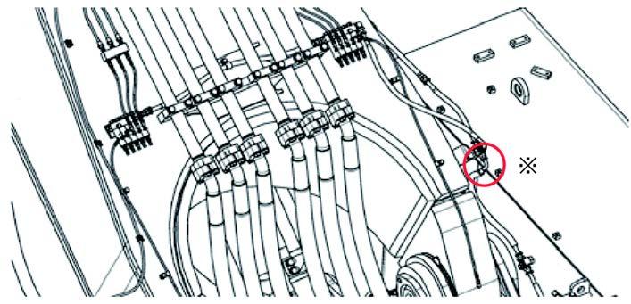
Connection between chassis and boom (Connecting parts of revolving frame and boom seen from rear upper direction of machine)
Connection between boom and arm (Connecting parts of boom and arm seen from right of machine)
Remove the oil stopping parts marked with ※ and connect the hoses and T-pieces.
Oil stopping parts Hose side 07376-50422 (Plug) T-piece side 07222-00414 (Plug) 07221-20422 (Nut)
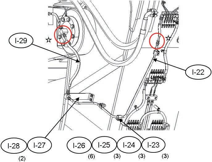
Remove the oil stopping parts marked with A and connect the hoses and T-pieces (2 places).
Oil stopping parts Boom side (Nipple) 07222-00414 (Plug) 07221-20422 (Nut) Arm side (Hoes) 07376-50422 (Plug)
No. Part No. Parts name Q'ty I-22 21T-68-31830-NK Tube 1 I-23 203-973-5660-NK Clamp 3 I-24 203-973-5720-NK Seat 3 I-25 21T-04-31620-NK Plate 3 I-26 01024-81055 Bolt 6 I-27 21T-70-32330-NK Bracket 1 I-28 01024-81225 Bolt 2 I-29 07631-20409 Hose 1
Precautions
• Grease pipings can be installed before the connection of the arm. Tools required
Name
30 mm Spanner
32 mm Spanner Q’ty
1
1 Equipment required
Name Q’ty
Others