8001
Engine p.
62
LUBRICATION FtGURA 108
Oil pump and relief valve inspection
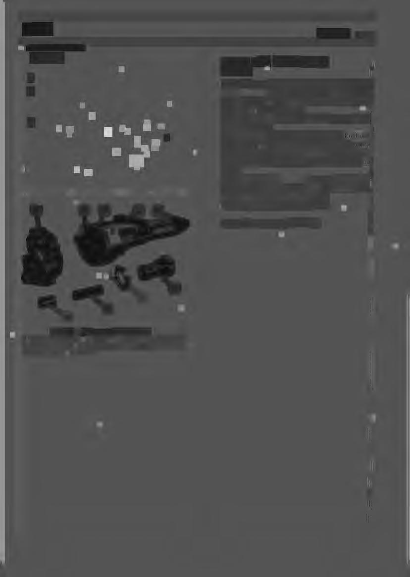
LUBRICATION SYSTEM COMPONENTS I . Oil suction scoop - 2. Pressure relief valve - 1 Oil pump - 4. Delivery line.
In the course of pump overhaul check clearance between gears (2-3 ) and pump cover face; correct clearance is .025 to .126 mm, maximum permissible clearance being .15 to .20 mm. The drive gear (5) is pinned to the oil pump shaft, the pin being staked. Also check clearance between shaft and lower bushing, which should be .16 to .35 mm, and between pump body outer sleeve and bearing in engine block. This is necessary because oil pressure has direct access to these parts. Check that the valve (9, ) moves freely in its housing and that it is free from signs of pick-up and score marks. Furthermore, using tool . check control spring (8) calibration data. Valves open at a pressure of 4.8 kg .
Fig. 58 1. Pump body cover 5. Pump drive gear 8. Valve spring - 9.
Oil pump components - 2. Gear - 3. Gear - 4 . Pump body 6. Oil pressure valve body - 7. Retainer Valve