11 minute read
LUBRICATION

LUBRICATION
FtGURA 108
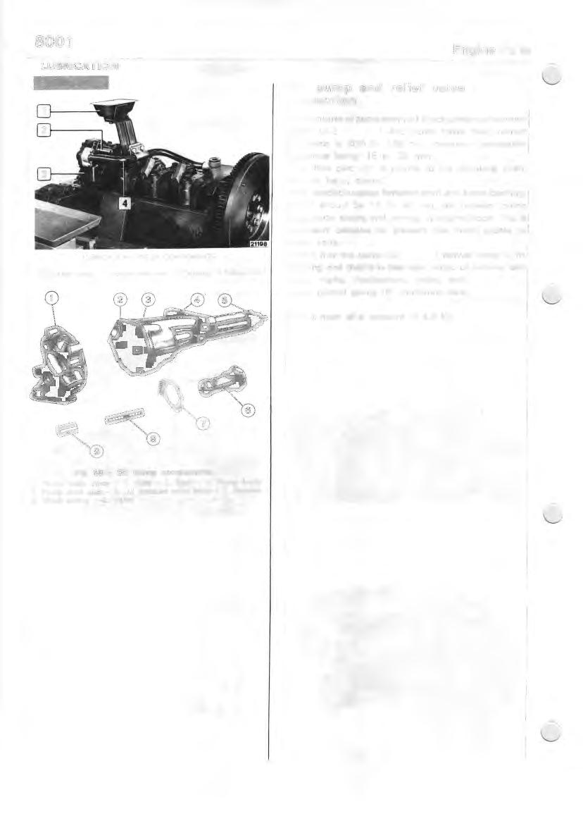
LUBRICATION SYSTEM COMPONENTS
I . Oil suction scoop - 2. Pressure relief valve - 1 Oil pump - 4. Delivery line.
Oil pump and relief valve inspection
In the course of pump overhaul check clearance between gears (2-3 ) and pump cover face; correct clearance is .025 to .126 mm, maximum permissible clearance being .15 to .20 mm. The drive gear (5) is pinned to the oil pump shaft, the pin being staked. Also check clearance between shaft and lower bushing, which should be .16 to .35 mm, and between pump body outer sleeve and bearing in engine block. This is necessary because oil pressure has direct access to these parts. Check that the valve (9, ) moves freely in its housing and that it is free from signs of pick-up and score marks. Furthermore, using tool . check control spring (8) calibration data.
Valves open at a pressure of 4.8 kg.
Fig. 58 - Oil pump components 1. Pump body cover - 2. Gear - 3. Gear - 4. Pump body 5. Pump drive gear - 6. Oil pressure valve body - 7. Retainer 8. Valve spring - 9. Valve
Water pump
6
0.5-c0,7
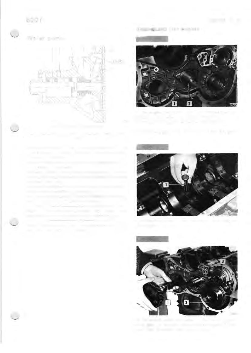
ASSEMBLING THE ENGINE
CROSS-SECTION OF WATER PUMP
21199
I . Hub - 2. Shaft w ith bearing - 3. Screw - 4. Pump body - 5. Seal - 6. Cover 7. Rotor.

The water pump is of the centrifugal vaned type. The pump bearing is intergrally cast with the rotor shaft and is boxed at the ends. Water seal between the pump body (4) and the shaft (2) is by means of the seal (5). The seal is fitted in the water pump body (4) so that water cannot leak between the outer surface of the seal and the pump body. The seal fitted in the housing provided for it in the rotor complements the effect of seal (5). The bearing stop screw (3) must be fixed in its housing with "LOCTITE 242" sealing compound.
NOTE - The rotor and fan pulley hub (7 and I) are fitted on the bearing shaft without retaining pins.
When assembling the pump, make sure the rotor (7) is flush with the end of the shaft (2). Fix the engine block to the revolving overhaul stand no. 99322205 by means of brackets 99361033. Fit the camshaft bushes as per the instructions •
Fix the timing gear (I); fit the pin (2) for the idler gear.
Lubricate the tappets (I) and fit them in their seats on the engine block.
Fit the vacuum pump drive gear (3), the injection pump drive gear (2); lubricate the camshaft supports ( I ) and insert the camshaft in the engine block.
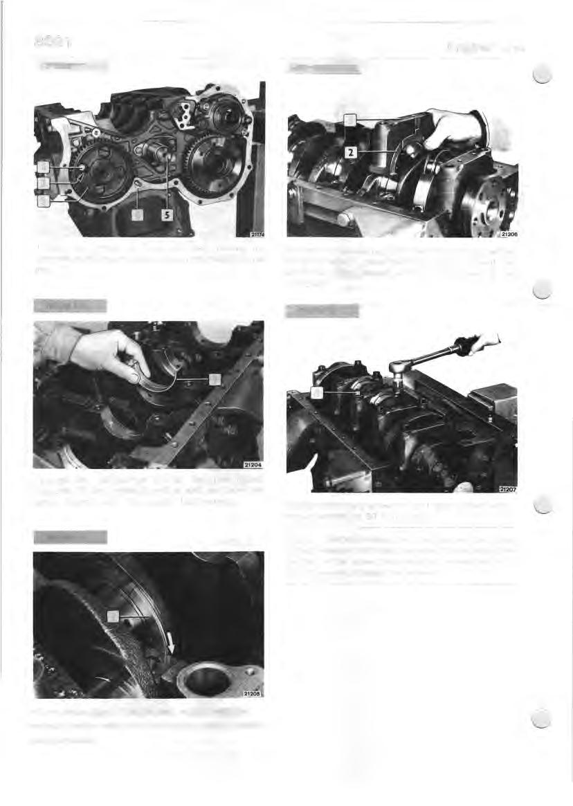
Tighten the screws ( I ) fi xing the plate holding the camshaft on the engine block through the holes (2) in the gear (3). Fit the main journal caps and the half-bearings; before fitting the caps (I), place the thrust washers (2) with the anti-friction alloy coated surface turned towards the· crankshaft.
FIGURE 121

Arrange the half-bearings (I) on the main journal supports; lift the crankshaft with a hoist and cable and gently lower it onto the support half-bearings. Lubricate the fixing screws ( I ) and tighten them with a torque wrench to 80 Nm torque.
NOTE - Before reusing the main journal cap fixing screws, measure the thread diameter 40 to 60 mm from the start of the screw; this should not be less than I 3.5 mm; otherwise, change the screws.
Fit the thrust rings (1) on the last support with the surface covered with anti-friction alloy turned towards the crankshaft.
FIGUMlll
Fit tool ( I) on the angle wrench (2) and tighten the screws a further 90°.
Check the coupling play between the main bearings and the crankpins as instructed Check the crankshaft end float as described Fit the engine flywheel ( I) according to the instructions in the relative


Turn the engine round , placing it on the vertical. With expander 99360605 ( I ) fit the pistorv'connecting rod assemblies (3) in the cylinder liners, as instructed .
Fit the rear cover (I) complete w ith oil seal (2) on the engine block; to fit the seal use plate 99360454. Fit the connecting rod caps (2) complete with the halfbearings; turn the engine round, so that the shaft is pointing upwards; with a torque wrench (I), tighten the screws (3) to a torque of 40 Nm; lubricate the screws first.
INOTE - Before reusing the connecting rod cap fixing f screws, measure the diameter of the thread I 9 to 35 mm from the start of the screw; this should not be less than I 0.6 mm; otherwise, use new screws.
FIGURE 129
FIGURE 127
Turn the engine round and bring cylinder no. I to T.D.C. in the compression phase; this position is obtained when the notch (2) on the fl ywheel matches up to the O (I). on the graduated sector.
FIGURE 130
Fit the tool ( I ) on the angle wrench and tighten the screws (2) a further 60°. Check that it is possible to move the connecting rods axially on the crankpins.
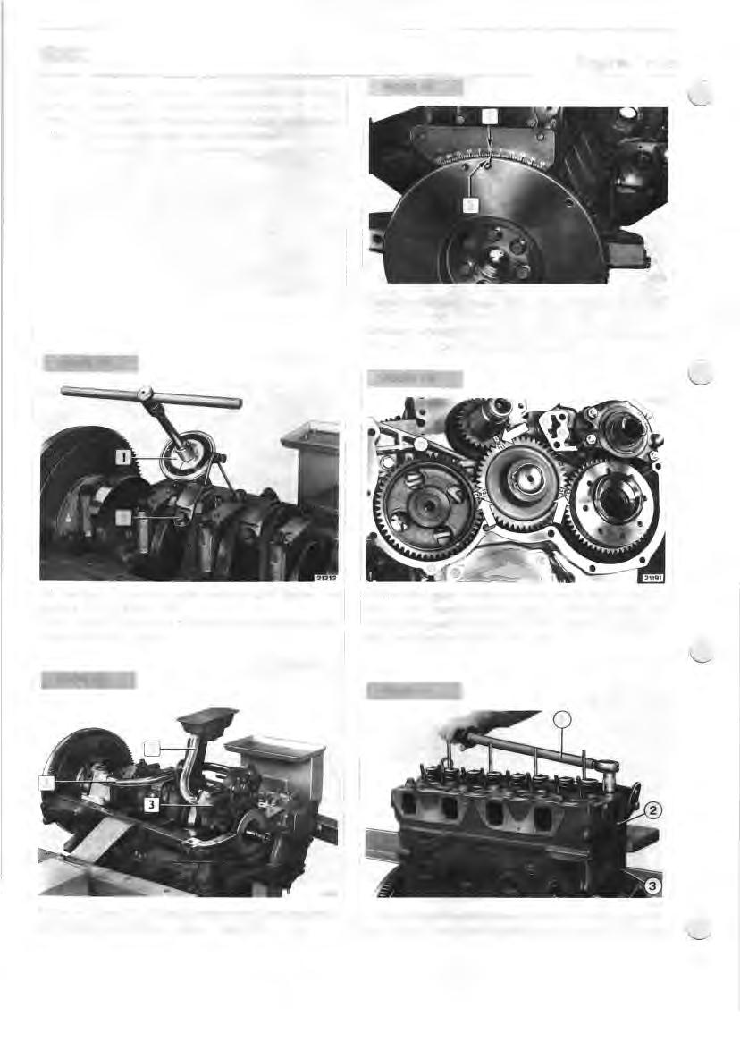
FIGURE 128
I Fit the idler gear, turning it so that the marks I, 2 and 3 (see arrows) stamped on it match up with the marks cut in the drive gear, the marks on the camshaft driven gear and the injection pump drive gear.
Fit the oil pump (3): fit the speedometer gear mounting and intake and delivery pipes ( I and 2).
5616
Turn the engine to the normal position. Fit the gasket, fit the cylinder head, then tighten the screws as instructed,
Fit the rocker arm pushrods (I) in their seats. Fit the coupling union (I), remembering that the mesh is located by a double tooth and a double cavity.

Fit the caps ( I ) on the valve stems.

Fit the rocker arm shaft complete ( I ). Adjust working play between valves and rocker arms as instructed.
INJECTOR HOLDER CASE
FIGURE 146
20983
If the engine shows loss of compression, especially around the injector seats, the fault is due to incorrect coupling between the injector carrier and the case force fitted in the cylinder head, or between the case and the cylinder head. This can be rectified by regrinding the seat at the end of the case or by replacing the case (2).

Fit the new case as follows: D fit the seal on the new case ( I ). D fit the new case with a suitable driver tool; D using the suitable tool cold head the lower part of the case: D regrind the seat of the case with a suitable grinder tool, making sure that the nozzle standout from the lower face of the cylinder head is 0.05 to 0.7 mm.
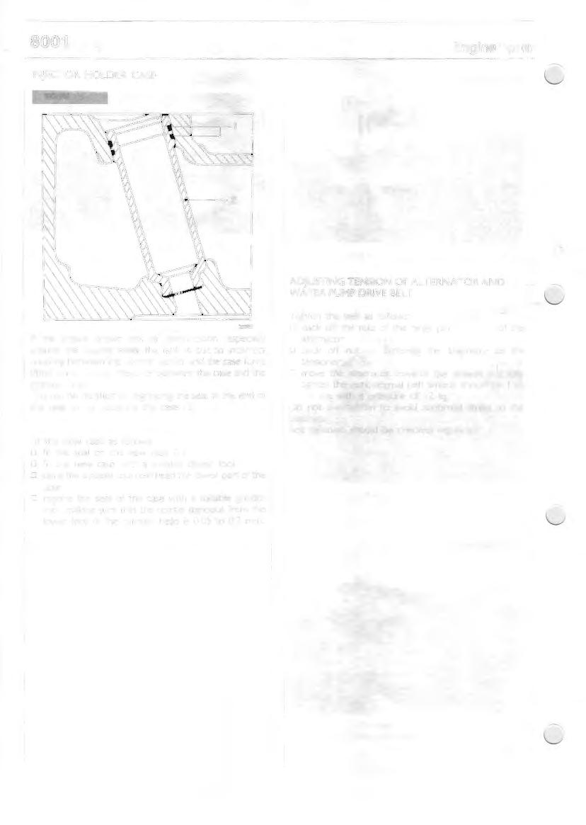
ADJUSTING TENSION OF AL TERNA TOR AND WATER PUMP DRIVE BELT
Tighten the belt as follows: D back off the nuts of the hinge pin of the alternator; D back off nut fastening the alternator to the tensioner; . D move the alternator towards the outside an1d fully tighten the nuts; normal belt tension should b~ I to
I .5 cm with a pressure of I 2 kg. Do not overtighten to avoid abnormal stress to the bearings. Belt tightness should be checked regularly.
CYLINDER GROUP
1st MEASUREMENT
2nd MEASUREMENT
3rd MEASUREMENT
20581
DIAGRAM FOR CHECKING DIAMETER OF CYLINDER LINERS
PISTON AND CONNECTING ROD ASSEMBLY
FITTING CYLINDER LINERS
When fitting the cylinder liners in their seats on the engine block - using a press - pay attention to the following: · D check that the outside diameter of the liners is mm
I 06.970 to I 06.940 and that the internal diameter of their seats on the engine block is I 06.850 to I 06.900 mm; o lightly smear contact surfaces with engine oil; D set the liner in its seat on the engine block and start press-fitting; D after pressing in 70 to 90 mm check that the load is over 5,000 N and below 23,000 N: . D continue fitting and check I 0 mm before completion that the load is between I 0,000 and 40,000 N; D on completion of fitting, consolidate for 2" with a bedding load over 50,000 N; D make sure edge of engine block contact with a bedding blow. If the press-fitting load is not within the above limits, remove the cylinder liner and replace it with another. After press-fitting, the cylinder liners must be reamed out and ground.
2,530 2,550 4,030 4,050 103,852 103,870
37,993 38.000
l37.983
37,990
MAIN DAT A REGARDING PISTON, PISTON RINGS AND PIN
• Measurements were taken on a diameter of IO I mm.
---"~1.Q_
DETAIL Of THE FIRST TAPERED GROOVE FOR THE COMPRESSION RJNG 20582
CONNECT! NG RODS
38.004. 38,014
I
37.983 37.990
lt805L
I
20581
MAIN DAT A REGARDING THE CONNECTING ROD. THE PIN BUSH AND THE HALF BEARINGS
• Measurements to be obtained after fitting the bush.
NOTE - After fitting the bush in the small end remove the part protruding from the side and then skim the bush to obtain the prescribed diameter.
CYLINDER HEAD
The following section describes the points on which en- I gines "SI.. differ from the previously described I engine "1.:·.
,c
It)
0
Exhaust
Intake
Reference dia. 36.4 I-" 432
2058S
MAIN DET .A.!LS OF INT AKE AND EXHAUST VAL VE SEA TS
TORQUE LOADS
COMPONENT
Cylinder head capscrew stage I : pretightening stage 2: pretightening stage 3: angle stage 4: angle
Capscrew, main bearing caps { pretightening angle
Capscrew, connecting rod caps { pretightening angle
Flywheel fixing screw { pretightening angle
TORQUE Nm (kgm) min. max.
70 ( 7,1) 70 (7,1) 90° 90°
80 (8.2) 90°
40(4.1) 60°
40 (4. 1) 60°
SPECIAL TOOL
TOOL NO.
DESCRIPTION
Support frame for removed engine. Flywheel hub remover. Remover for pulley hub and water pump impeller. Sliding hammer. Tool part for removing clutch shaft guide bearing (for use with 99340205). Injector case extractor. Spanner for rocker arm tappet play adjusting screw. Spanner for oil pipe plugs in engine block. Pl iers for assembling rings on the piston. Driver for removing valve guide. Tool for removing filter cartridges. Flywheel restrainer. Engine valve remover/installer. Installer for crankshaft front seal (use with 99370007). Installer for crankshaft rear seal (for use with 99370006). Drift for fitting sealing gasket for water pump drive. Test connection for cylinder pressure (for use with 99395682). Ring-bolt for lifting and transporting cylinder group. Tube for inserting pistons in cylinders. Brackets for fixing engine to revolving stand. Injector case header tool. Interchangeable hand-grip for drifts. Interchangeable hand-grip for drifts. Drift for fitting crankshaft core plugs. Valve guide hole reamer. Set of screw-taps for threading injector holder cases for removal. Reamer for reboring the lower part of the injector holder case (use with 99394079). Cutter for regrinding injector seat ( use with 99394019). Guide bush. Graduated sector for checking engine timing on bench.
Drive cylinder compression tester (for use with 99360647).
SPECIAL TOOLS
TOOL NO.
ENGINE 99315066 99340033 99340035 99340205
99342145 99350108 99357051 99360183
DESCRIPTION
Frame for holding the removed engine. Fl ywheel hub remover. Water pump rotor and hub pulley remover. Sliding hammer
lnJector case remover. Rocker arm clearance adjusting screw spanner. Engine block oil pipe plugs spanner. Pliers for piston rings assembly on pistons.
Valve guide remover. Valve guide assembler (use with 99360288). Filter cartridge remover. Flywheel restrainer. Valve installer/remover. Crankshaft front seal installer (use with 99370007). Crankshaft rear seal installer (use with 99370006). W ater pump impeller seal installer. Cylinder compression test union (use with 99395682). Sling for lifting crankshaft. Lug for lifting/transporting cylinder group (order n. 2 parts). Sling for removing/refitting engine. Tube for introducing pistons into cylinders (normal and oversized). Brackets for fixing engine to revolving stand. Spreader tool for injector cases. Interchangeable hand-grip for drivers. Interchangeable hand-grip for drivers. Driver for fitting crankshaft core plugs. Valve guide hole reamer. Set of screw taps for threading injector cases for removal. Reamer for injector housings (use with 993940 19). Cutter for grinding injector housing seat (use with 993940 19). Guide sleeve. Graduated sector for engine timing bench test.