15 minute read
FAULT-FINDING DIAGNOSIS

FAULT
The engine does not start
The stops
POSSIBLE CAUSE
REMEDY
Batteries low charge.
Battery terminals corroded or loose.
Incorrect timing of injection pump.
Deposits or water in fuel lines.
Insufficient fuel reserve.
Fuel supply failure.
Air bubbles in fuel lines or in injection pump.
Defective starter.
Inefficient thermostarter.
Electronic stop valve not working. Check and recharge the batteries. Change batteries, if necessary.
Clean, examine and tighten nuts on battery terminals. Change lead terminals and nuts, if badly corroded.
Check injection pump timing and reset if necessary.
Disconnect pipes and clean out with compressed air jet. Remove and clean the injection pump. Dry out the tank and refill with fuel.
Refuel.
Overhaul or change fuel or transfer pump.
Check the pipes to detect reasons for air in system and the fuel pump for an eventual diminishment of fuel; check if there is less fuel in the fuel pump; bleed air from inside the injection pump by unscrewing the appropriate plug and working the fuel pump by hand.
Repair or replace starter motor.
Switch on thermostarter at low temperature; if inefficient, change it.
Change the valve.
Too low idling.
Uneven injection pump deliveries.
Dirt or water in fuel lines.
Fuel filters blocked. Unscrew adjusting screw at end of hand throttle control cable.
Check deliveries.
Remove pipes and clean out with compressed air jet. Remove and clean injection pump. Dry out fuel tank and refill with fuel.
Remove filter elements and renew them if necessary.
Abnormal clearance between valves . Adjust clearance. and rockers.
Valves burnt out or cracked.
Air in fuel and injection systems.
Fuel filter blocked.
Injection pump controls broken. Renew the valves.
Check pipes for possible cracks or loose unions. Replace any worn parts, then bleed air from pipes and de-aerate injection pump and fuel filter by unscrewing the appropriate plugs and working the fuel pump by hand.
Change fuel filter.
Change faulty parts and check pump timing.
FAULT
ll'-na11111!'l under power and
POSSIBLE CAUSE
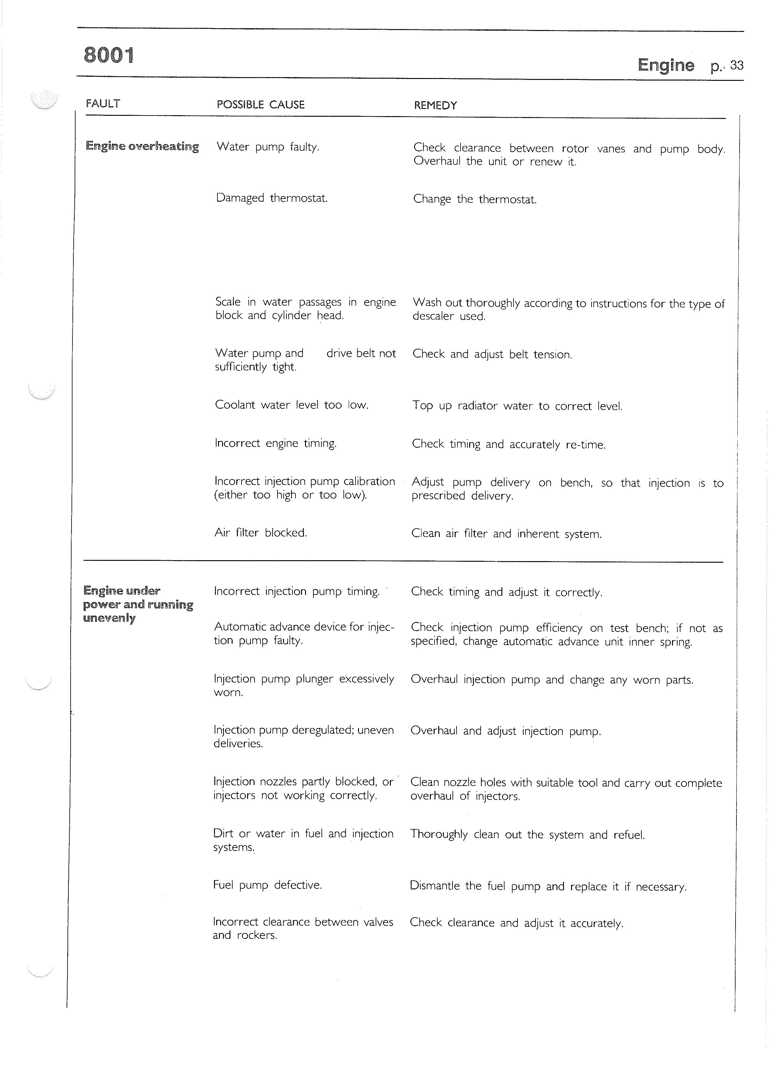
Water pump faulty.
Damaged thermostat.
REMEDY
Check clearance between rotor vanes and pump body. Overhaul the unit or renew 1t.
Change the thermostat.
Scale in water passages in engine block and cylinder head. Wash out thoroughly according to instructions for the type of descaler used.
Water pump and sufficiently tight. drive belt not Check and adjust belt tension.
Coolant water level too low. Top up radiator water to correct level.
Incorrect engine timing.
Incorrect injection pump calibration (either too high or too low).
Air filter blocked. Check timing and accurately re-time.
Adjust pump delivery on bench, so that injection is to prescribed delivery.
Clean air filter and inherent system.
Check timing and adjust it correctly.
Check injection pump effkiency on test bench; if not as specified, change automatic advance unit inner spring.
Incorrect injection pump timing.
Automatic advance device for injection pump faulty.
Injection pump plunger excessively worn. Overhaul injection pump and change any worn parts.
Injection pump deregulated; uneven Overhaul and adjust injection pump. deliveries.
Injection nozzles partly blocked, or · Clean nozzle holes with suitable tool and carry out complete injectors not working correctly. overhaul of injectors.
Dirt or water in fuel and injection Thoroughly clean out the system and refuel. systems.
Fuel pump defective. Dismantle the fuel pump and replace it if necessary.
Incorrect clearance between valves Check clearance and adjust it accurately. and rockers.
FAULT
Engine under power and running
unevenly
POSSIBLE CAUSE
REMEDY
Loss of compression.
Air filter blocked. With tool no. 99395682 (Motometer), check that pressure at T.D.C. in the different cylinders is equal and that the pressure reading is 21 kg/cm 2 ; if less, proceed to overhaul engine.
Clean air filter and inherent system.
Injection pump peak capscrew 1n- Adjust stops correctly. correctly adjusted.
Engine knocking abnormally
Engine smoke abnormally black or dark grey smoke:
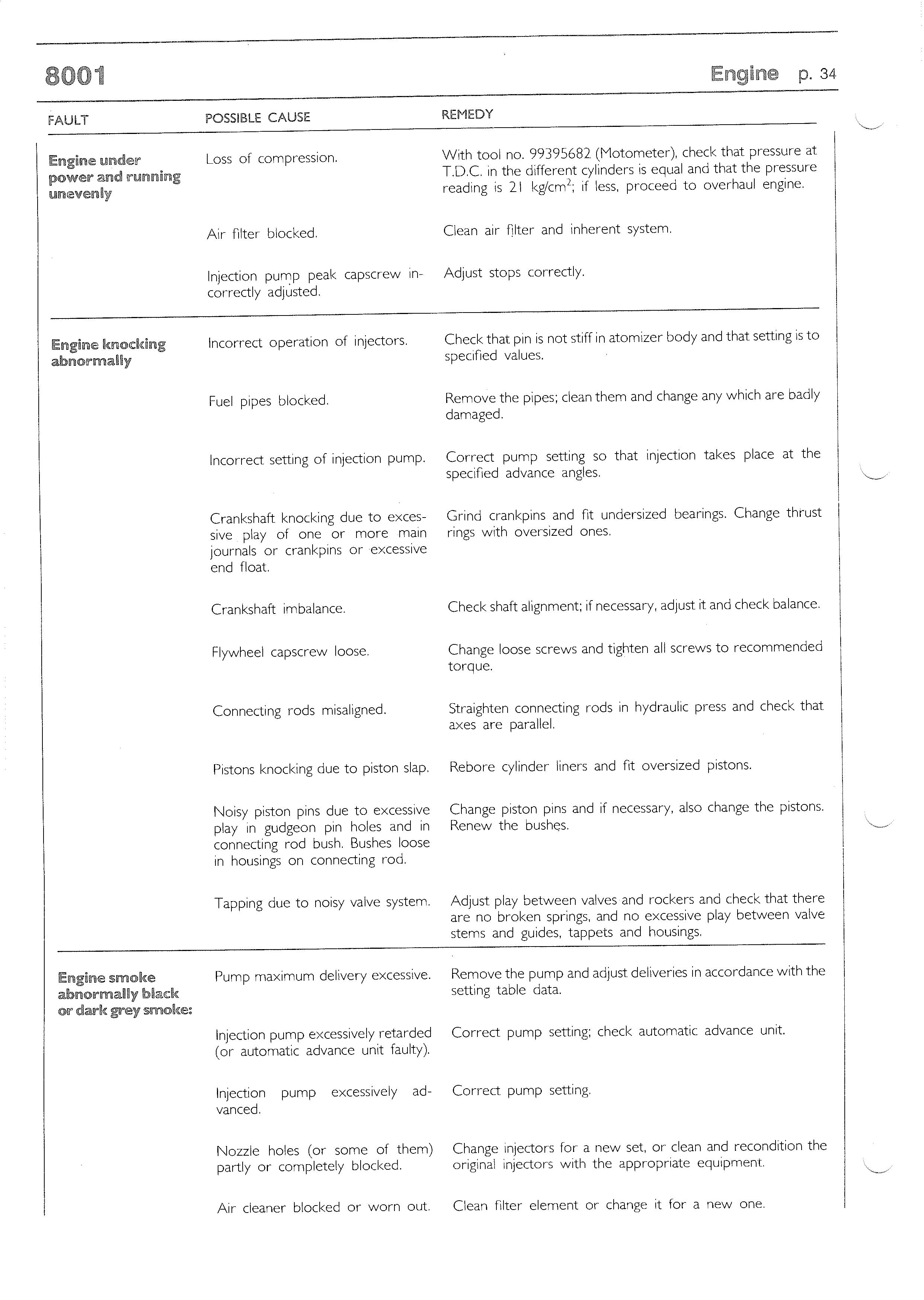
Incorrect operation of injectors.
Fuel pipes blocked. Check that pin is not stiff in atomizer body and that setting is to specified values.
Remove the pipes; clean them and change any which are badly damaged.
Incorrect setting of injection pump. Correct pump setting so that inJection takes place at the specified advance angles.
Crankshaft knocking due to excessive play of one or more main journals or crankpins or excessive end float.
Crankshaft imbalance.
Flywheel capscrew loose.
Connecting rods misaligned.
Pistons knocking due to piston slap.
Noisy piston pins due to excessive play in gudgeon pin holes and in connecting rod bush. Bushes loose in housings on connecting rod. Grind crankpins and fit undersized bearings. Change thrust rings with oversized ones.
Check shaft alignment; if necessary, adjust it and check balance.
Change loose screws and tighten all screws to recommended torque.
Straighten connecting rods in hydraulic press and check that a><es are parallel.
Rebore cylinder liners and fit oversized pistons.
Change piston pins and if necessary, also change the pistons. Renew the bushes.
Tapping due to noisy valve system. Adjust play between valves and rockers and check that there are no broken springs, and no excessive play between valve stems and guides, tappets and housings.
Pump maximum delivery excessive. Remove the pump and adjust deliveries in accordance with the setting table data.
Injection pump excessively retarded Correct pump setting; check automatic advance unit. ( 01- automatic advance unit faulty).
Injection pump excessively ad- Correct pump setting. vanced.
Nozzle holes (or some of them) partly or completely blocked. Change injectors for a new set, or clean and recondition the original injectors with the appropriate equipment.
FAULT
Black or dark grey smoke:
Blue, greyish blue or greyish white smoke:
The engine does not stop
POSSIBLE CAUSE REMEDY
Loss of engine compression due to: Overhaul the engine or simply repair faulty parts. o piston rings stuck; o cylinder liners worn; o valves deteriorated or misadjusted.
Unsuitable type of injectors fitted , or some injectors of different type fitted, or out of calibration.
Injection pipes of incorrect i.d. fitted; pipe ends damaged by repeated blockages. Change or calibrate injectors.
Check state of pipe ends or unions; if necessary, renew the pipes.
Injection excessively retarded or Correct pump setting and check automatic advance unit. automatic advance unit damaged.
Injector needles blocked or faulty Check whether needles jam or springs are broken. injectors.
Oil leaking from piston rings due to Overhaul the engine. jammed rings or wear on cylinder liner walls.
Engine oil leaking through intake Recondition the cylinder head. valve guide, due to wear on guides or valve stems.
Engine too cold (thermostat Jam- Renew the thermostat. med or resistant).
Governor broken. Repair as necessary.
Electric shut-off . broken.
Governor components stiff.
Excessive clearance between various parts of the governor. Repair as necessary.
Overhaul or renew.
Eliminate all play, allowing only minimum tolerances; change any worn-out parts.
DISMANTLING THE ENGINE
't FIGURE 20
Remove the water pump (I).
FIGURE 21 FIGURE 23
Remove the fuel pump ( I ).
FIGURE 24

Prevent the flywheel from turning by means of tool 99360352, straighten the lockplate ( I ) and back off the alternator/water pump drive pulley hub (3) locknut (2). Remove the vacuum pump (2) together with the drive union and injection pump ( I ).
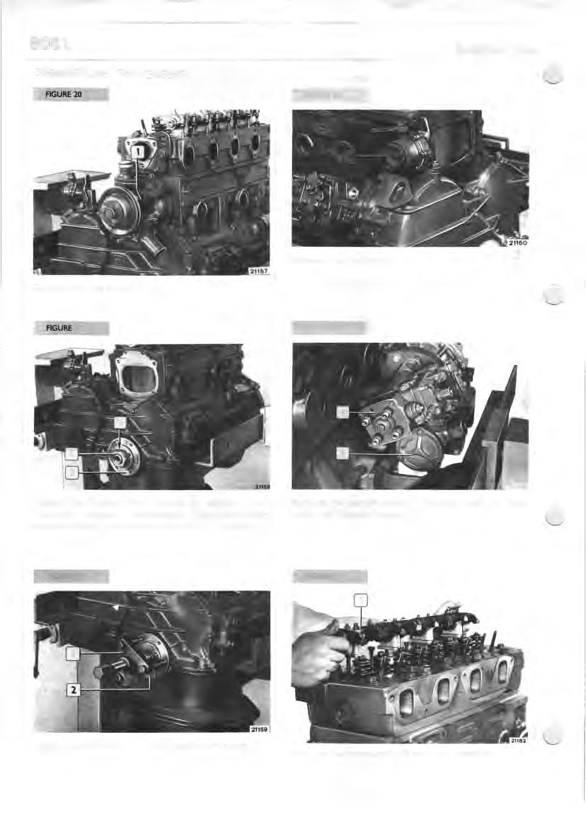
FIGURE 25
Apply tool 99340033 (I) and withdraw the hub (2). Remove the complete rocker carrier' shaft ( I ).
FIGURE 26 .
FIGURE 29
Recover the rocker arm pushrods (I) and the caps from the valve stem (2).
FIGURE 27
Take off the timing gear front cover ( 4 ). Remove the oil pump (3) and intake ( I) and delivery (2) pipes.
Back off the screws ( I ) fixing the cylinder head (2), remove the cylinder head and save the gasket.
FIGURE 28
Remove the retaining snapring (2) and withdraw the idler gear ( I ).
Unscrew the screws, remove the connecting rod caps ( I ) and recover the half-bearings.
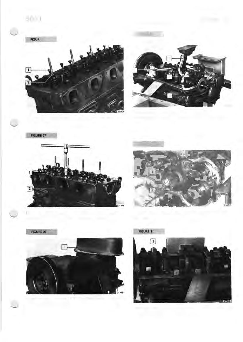
Turn the engine round I 80°, then remove the oil sump ( I ) and save the gaskets.
AGURE 32 FIGURE 35
Withdraw the piston/connecting rod assemblies (I) from the top of the engine block. Back off the setscrews (I) of the main journal caps (2) and remove them, recovering the half-bearings.
FIGURE 33 FIGURE 36
Undo the flywheel (2) setscrews (I) and remove it
FIGURE 3-4
Lift up the crankshaft ( I ) and remove it; recover the main half bearings (2) and the thrust rings.
Position the camshaft and back off the setscrews ( I ) of the thrust plate through the holes (2) in the gear; then withdraw the camshaft (3).
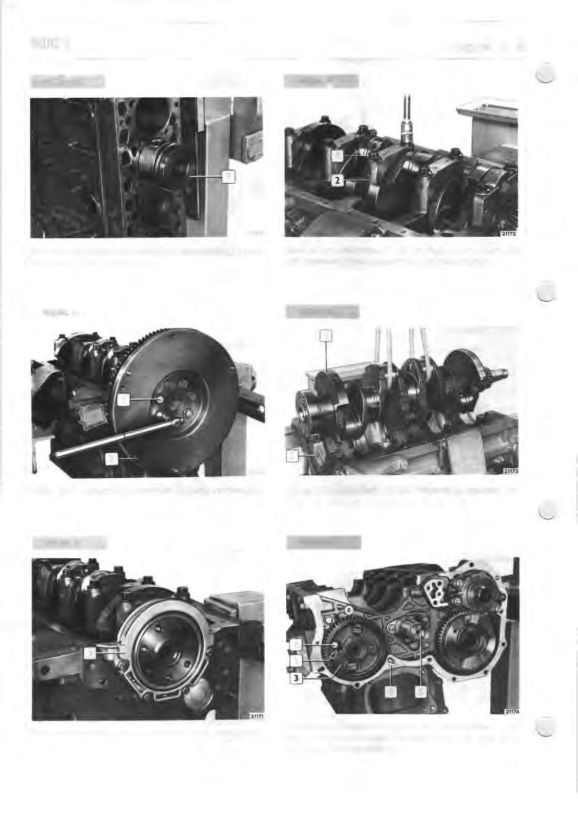
Remove the rear cover (I) complete with sealing ring.
Withdraw the tappets from their seats. Remove the timing gear case (4) complete with injection pump drive gear and vacuum pump. Remove the idler gear pin (5). the
I
CYLINDER GROUP
I st MEASUREMENT 104,000~104.024
ENGINE BLOCK
After engine disassembly, thoroughly clean the engine block and cylinders.
CHECKS AND MEASUREMENTS
NOTE - Never measure the cylinder liners loose, as they are easily distortable; measure the internal diameter with the liner fully fitted .

2nd MEASUREMENT
3rd MEASUREMENT
20395
DIAGRAM FOR CHECKING DIAMETERS OF CYLINDER LIN ERS
The above measurements should be carried out for each individual cylinder at three different heights on the liner and on two planes perpendicular to each other; the first parallel to the longitudinal ax is (a) and the 2nd perpendicular to (b) that axis, (b) w here, near the I st measurement, the maximum w ear is usually to be found . If ovality, taper or w ear are found , arrange to rectify them as a repair job, by grinding the liner if slightly worn or scored, or rebore and then grinding if scoring is deep or ovalisation is marked.
NOTE - If regrinding, all liners must be oversized the same (0.4 to 0.8 mm).
15256
The check of the inside diameter of the cylinder liners to control the degree of ovalisation, taper and wear should be done using a suitable gauge (2) fitted with a dial gauge in thousandths (I) previously zeroed on the ring gauge (3) with a diameter of I 04 mm.
NOTE - If a I 04 mm diameter ring gauge is not available use a moving gauge for outsides.
I 05
_J_
DIAGRAM OF BEVEL TO BE MADE O N CYLINDER LI NERS AFTER REGRINDIN G
Dismantling and refitting cylinder liners in the cylinders should be carried out w ith a hydraulic press and the appropriate plates. When fitting cylinder liners in their housings in the engine block, under a press, pay attention to the following: o check that the external diameter of the cylinder liners is I 07.020..,... I 07.050 mm and that the internal diameter of their seats in the engine block 1s
I 06.850-,- I 06.900 mm; o smear surfaces to be coupled with engine oil ; o set the liner in its seat in the engine block, then start the pressing: o after pressing in 70 to 90 mm, check that the load is 12.000..,... 34.000 N: o continue pressing and recheck IO mm before completion that the load is 30.000-,- 70.000 N .
If the press load is not within the above-mentioned limits, remove the cylinder liner and replace it with a new one. After press-fitting the liners should be reamed out and ground. They are actually supplied as spares with internal diameter slightly less than the nominal dimension to enable any deformations that may occur during fitting to be corrected . Cylinder liners are supplied as spares with their external diameter oversized by 0.2 mm. Check flatness of support surfaces (3) of the cylinder head by means of a straightedge (I ) and feeler gauge (2). After detecting distortion areas, smooth the face w ith a grinder, taking care to remove the minimum possible amount of material.
NOTE - Remove centering dowels only if it is necessary to skim the contact face of the block.
5592
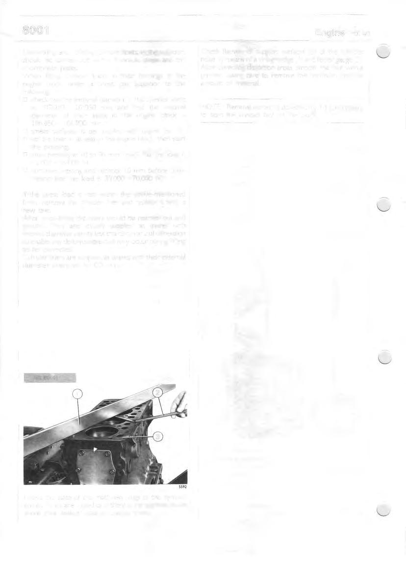
Check the state of the machined plugs of the cylinder group: if they are rusted or if there is the slightest doubt about their sealing capacity, change them.
CRANKSHAFT
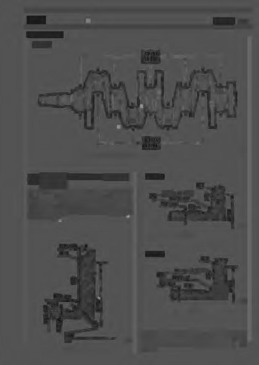
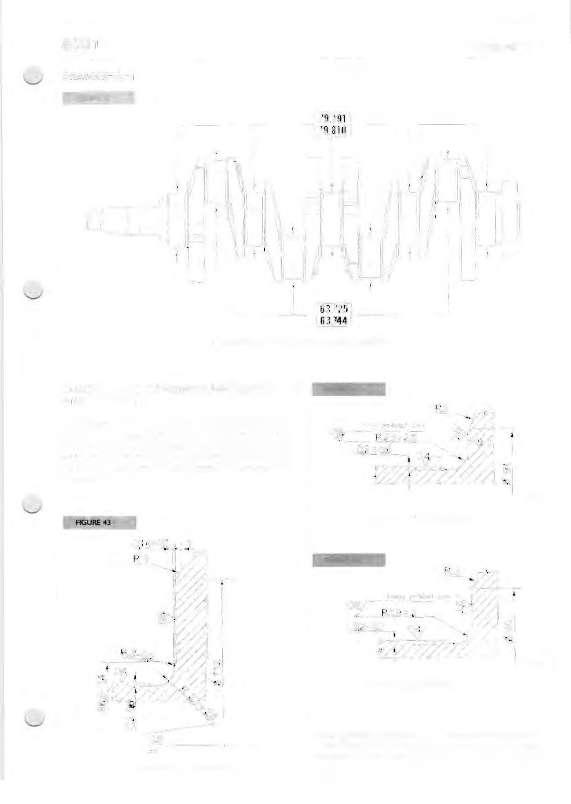
FIGURE 42
- --------< 79,791 79,810 1---------
L-- - - ---'-----1 63,725 ,_ ....______ _ __ 63.744
DETAILS OF CRANKSHAFT MAIN JOURNALS AND CRANKPINS
CHECKI NG AN!) GRINDING MAIN JOURNALS AND CRANKPINS
If any traces of seizure, scoring or ovality is found on the main journals and crankpins, they must be reground. Before carrying out grinding, with a micrometer measure the pins and establish on the basis of the undersize range of the bearings to what diameter it is necessary to reduce the pins.
FIGURE<M
DETAIL OF MAIN JOURNAL FI LLETS
DETAIL OF CRANKPIN FI LLETS
When grinding crankshaft pins, pay maximum attention to the fillet values, which must not change at all with reference to the dimensions quoted in Figures 43, 44 and 45.
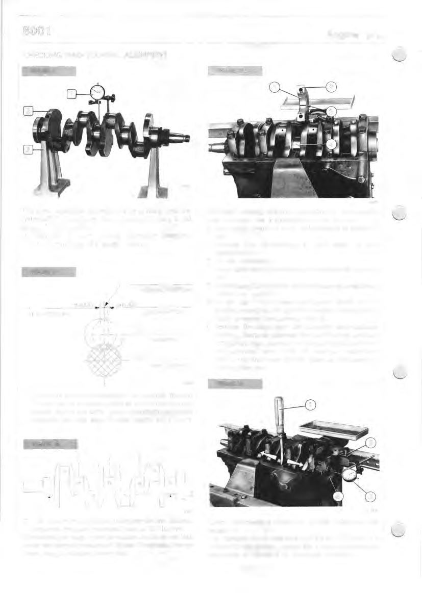
CHECKING MAIN JOURNAL ALIGNMENT
FIGURE 46 FIGURE 49
This check should be carried out after grinding, with the crankshaft (2) resting on two V-blocks (3), using a dial gauge (I) for checking. D Alignment of main journals: maximum tolerance > 0. IO mm (total dial gauge reading).
FIGURE 47
LIMIT POSITION NORMAL POSITION
LIMIT POSITION
CRANKPINS
MAIN JOURNALS
6236
D Crankpins alignment relative to main journals; the axis of each pair of crankpins and that of the main journals should be on the same plane; maximum permitted tolerance at right angle to that plane: ± 0.25 mr.
FIGURE 41
S607
To check existing clearance between the journals and their bearings, use a calibrated line, as follows: D thoroughly clean the parts and eliminate all traces of oil; D arrange the half-bearings in their seats on the supports; D fit the crankshaft; D run a calibrated (3) wire along the crankshaft journals (4); D fit the caps (2) complete with half-bearings, onto their respective supports; o fit the cap fixing screws and tighten them w ith a torque wrench at the specified torque, having previously smeared the screws w ith oil; o remove the caps from the supports and calculate existing clearance between the half-bearings and the crankshaft main journals by comparing the width of the calibrated wire (3) at the maximum projection point, with the mark on the scale on the case for holding the line.
FIGURE SO
6237
o The maximum permitted tolerance for the distance between the shaft rotational axis is · ± 0. IO mm. Check that the plugs in the lubrication circuit do not leak under an internal pressure of I 5 bar: if they leak, change them using a suitable driver tool.
S610
Check and measure crankshaft (4) end float using dial gauge (3). The standard fitting clearance is 0.082 to 0.334 mm. If it is found to be greater, change the thrust ring halves for new ones of standard or oversized thickness.
DYNAMIC BALANCER
Balancer Overhaul
When removing the dynamic balancer note the following points: - Drain the engine oil pan and remove the bottom cover. Check for wear, replace any defective parts, and ream the new bushings using expansion blade reamers.
To install bushings, heat the weights in oil at 140 ° to 160 ° C.
Dynamic Balancer Schematics
10. Housing - 11 . Flyweight drive gear - 13. Sleeve - 18. Drive pinion - 19. Intermediate gear - 27. Flyweights - 34. Idler gear - 40. Crankshaft.
- Take off the suction scoop, remove the fixing screws of the box to the oil sump and take off the flyweight assembly.
- If necessary, remove gear (18) with attached flange, withdrawing oil pipe and capscrews.
To disassemble the flyweight assembly proceed as follows :
- Withdraw roll pins (25) and take off the weight carriers using a suitable driver.
- Remove flange retaining screws (7), retaining ring (30) and flyweight drive gear (11 ).
a
Removing Flyweight Carriers
a. Section through idler gear - F. Oil ports - 7. Flange capscrew - 11 . Flyweight drive gear - 25. Roll pins - 26. Flyweight carrier - 27. Flyweight - 28. Flange - 29. Thrust washer - 30. Retaining ring - 35. Idler gear carrier - 36. Retaining ring - 37. Thrust washer - 38. Thrust washer.
Installing Dynamic Balancer (10) with Sleeve (13)
Timing marks arrowed . a. Installing oil pipe - 14. Retaining ring - 15. Thrust washer 19. Intermediate gear - 39. Lockring pin.
When assembling parts, make sure that flyweight drive gear (11) and flyweights (27) are positioned so that all reference marks are as arrowed. Note that :
- Idler gear (34) should be positioned with the longer end of hub facing towards the housing wall.
- Roll pin holes (26) in flyweight carriers should be aligned with associated holes in the housing.
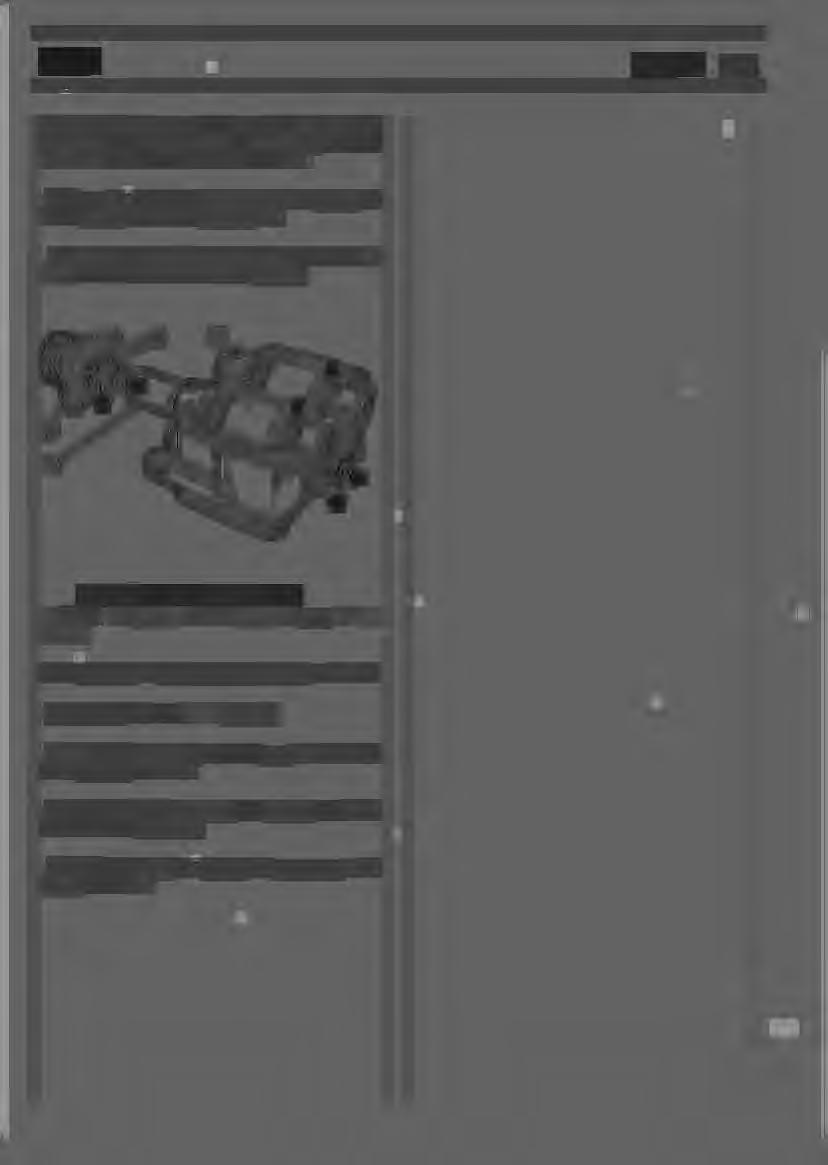
Dynamic Balancer Timing Marks
13. Sleeve - 16. Flange - 18. Drive pinion and gear - 27. Flyweights.
When installing the flyweights, adjust timing as follows :
- Bring piston No. 1 to T.D.C. position.
- Secure drive pinion (18) to the oil pan, with reference marks aligned as shown.
- Lock the flyweights in position with pin (39) and check reference mark alignment,
- Position sleeve (13) and tighten the capscrews to the torque of Nm 110.