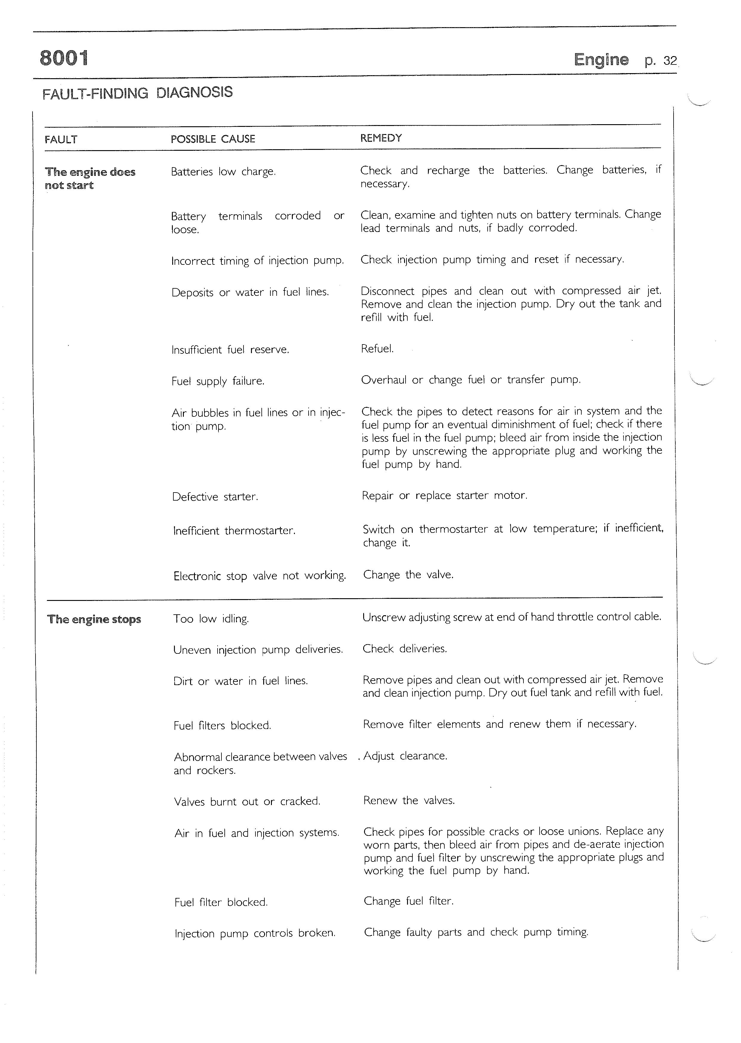
7 minute read
CONNECTING RODS

CONNECTING RODS
FIGURE 66
NOTE - Each connecting rod is marked on the body and cap with a number matching that of the cylinder in which it is to be fitted . If replacing the connecting rod , therefore, it is necessary to number the new one with the same number as the one it replaces.
15263 Check that axes of connecting rods are parallel. Permitted tolerance is 0.07 mm measured 125 mm from the longitudinal axis of the connecting rod .
FIGURE 69
3987
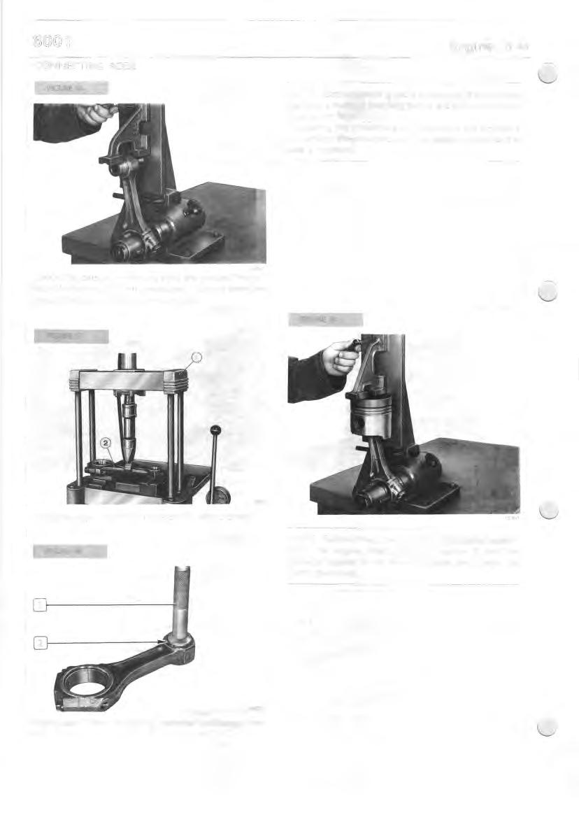
Straightening a connecting rod stem (2) using a press (I).
15264
NOTE - Before fitting the connecting rod/piston assembly in the engine, check that it is square. It must be perfectly square; if not, trace the cause and change the parts concerned.
21187
Fitting bush (2) for connecting rod small end, using driver (I).
FIGURE 70 FIGURE n
41,979 . 42 .017 38,004* 38,014
1 37,9831 37,990
6 7.1,0 7 67,1.22 1,805 1,815
0
63 ,725 73 .7 44

20396
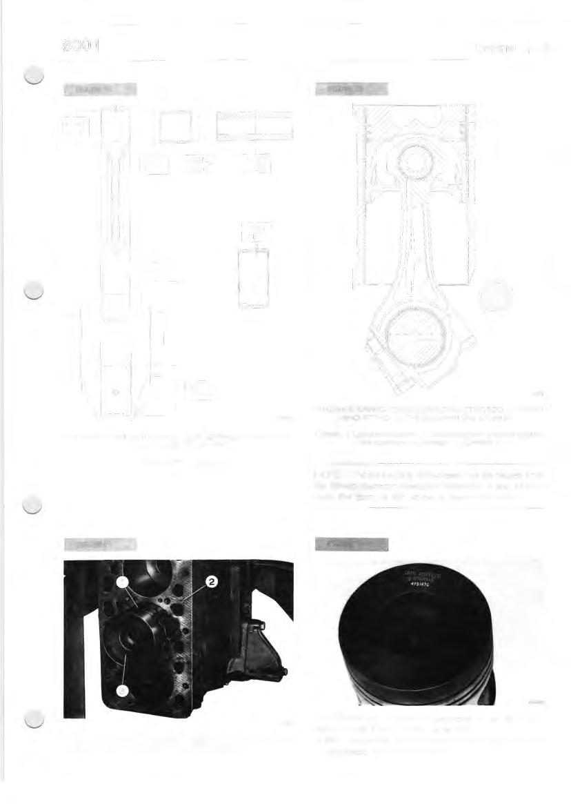
DETAILS OF CONNECTING ROD, BUSH, BEARINGS, CONNECTING ROD PIN AND PISTON PIN
* Measured after fitting bush. 4
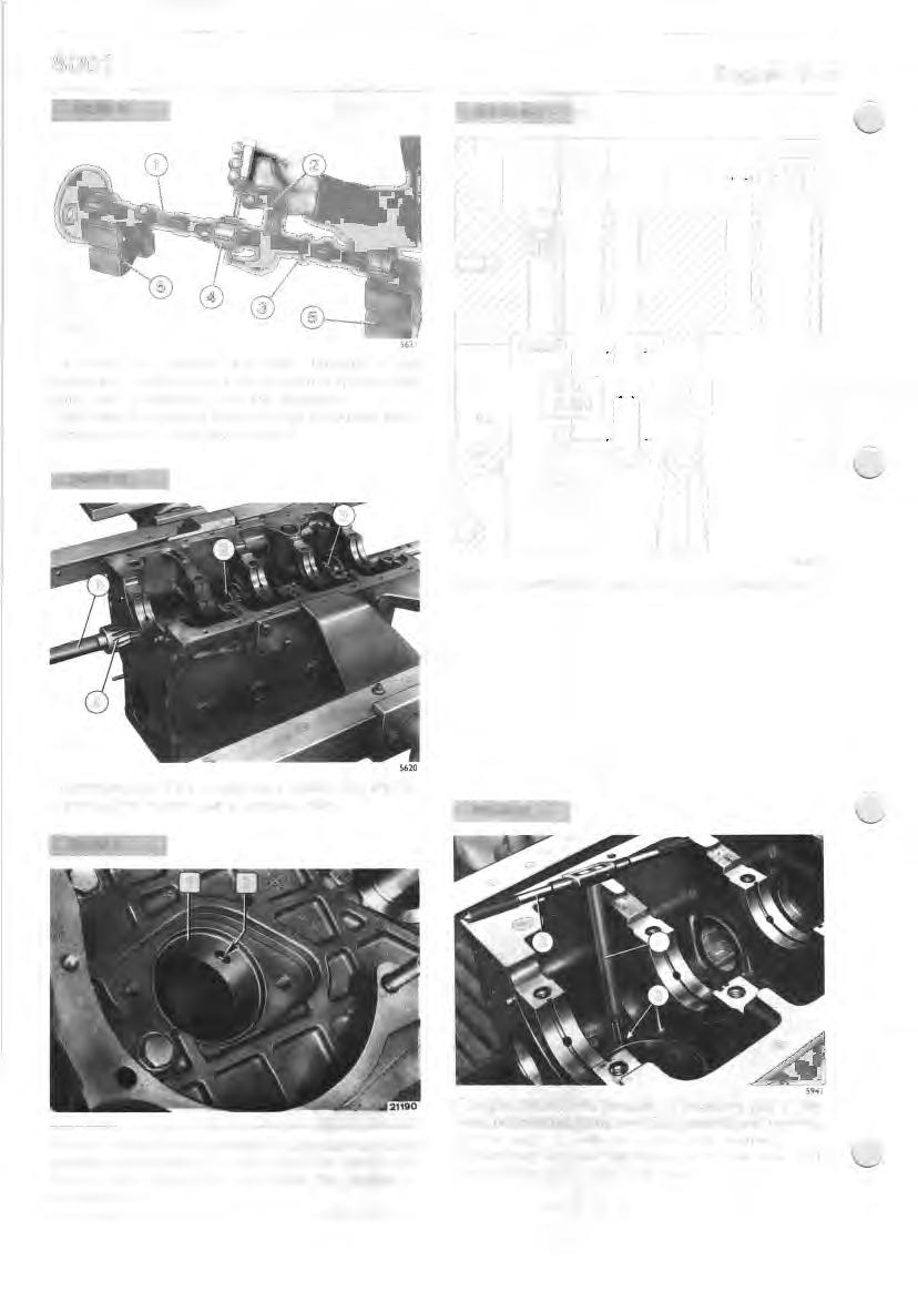
DIAGRAM SHOWING COUPLING OF CONNECTING ROD TO PISTON AND FITTING OF THE GROUP IN THE CYLINDER
I . Piston -2. Combustion chamber - 3. Stamped number of cylinder to which the connecting rod belongs - 4. Camshaft.
NOTE - The connecting rod screws may be reused until the thread diameter measured between I 9 and 35 mm from the start of the screw is below I 0.5 mm.
FIGURE 71 FIGUM 73
5632
Fitting connecting rod/piston assembly (3) in cylinder liners using compression ring 99360605 ( I ). The connecting rod/piston assemblies must be introduced in the liners, making sure that: D the connecting rod number corresponds to its associated cylinder number:
The assembly of the connecting rod-piston assembly in the liners should be carried out checking that: o the number of the connecting rod corresponds to the number of the cylinder; o the wording "LA TO PUNTERIE" (TAPPETS SIDE) stamped on the crown of the piston is turned towards the camshaft; o the connecting rod numbers are positioned on the opposite side to the camshaft; o the ring gaps are offset I 20° to each other. Lubricate the pistons well, including the piston rings and the inside of the cylinder liners.
FIGURE 75

FIGURE 74
6921
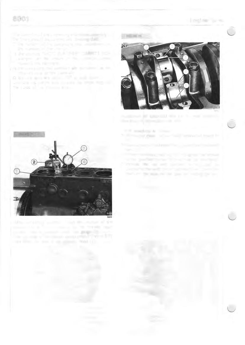
Application of calibrated line (3) to read assembly clearance of connecting rod pins.
Check clearance as follows:
D thoroughly clean the parts and remove all traces of oil;
D place a piece of calibrated line (3) along the crankshaft pins (2); o fit the connecting rod cap (4) and tighten the screws to the specified torque (screws must be lubricated); . D remove the cap and calculate existing play by comparing the width of the calibrated line (3) with the mark on the scale on the case for holding the line.
5603
After completing assembly, check the position of the pistons (4) at T.D.C. relative to the cylinder head surface, using a magnetic-based dial gauge (3). The top edge of the pistons should project 0.46 to 0.79 mm from the face of the cylinder head ( I ).
FIGURE 76
The surfaces of the shaft support pins and of the cams should be extremely smooth; if there are any signs of pick-up or scoring, change the shaft and its bu~hes.
0
54,280 54.3 0 5
0
FIGURE n
51.,875 54,930
50,470 50.50 0 54,3 75 54,430
DETAILS OF CAMSHAFT, BUSHES AND HOUSINGS IN ENGINE BLOCK
FIGUM78
50,080 50,130
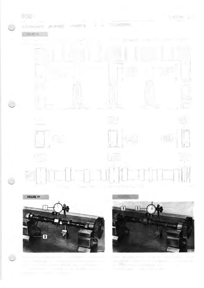
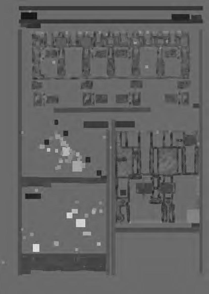
Place the camshaft on two parallel blocks (3) and check with a dial gauge (I), the alignment of the support pins (2); misalignment should not be over 0.020 mm. If misalignment is found to be greater than this, straighten the shaft in a press. With the camshaft (I) still on the parallel blocks, check the cam lift (3) height with a dial gauge (2); this should be: D 5.955 mm for the intake cam; D 6.027 mm for the exhaust cam.
FIGURE 79 FIGURE 82
1~
1 1
5621
To check play, measure the inside diameter of the bushes and the diameter of the camshaft ( I ) journals ( 4 ); actual play is obtained from the difference. If play over 0. 160 mm is found, change the bushes and if necessary, also change the camshaft.
20399
DETAILS OF TAPPETS AND THEIR SEA TS ON THE ENGINE BLOCK
5620
To remove and fit the bushes use a suitable tool and for skimming the bushes use a suitable miller.
FIGURE 83
NOTE - When fitting the bushes (I) pay attention to the direction of the holes (2), wich should be aligned with those in the engine block to enable the passage of lubrication oil.
59~1
Changing the tappets, because of excessive play in the seats, necessitates fitting oversized tappets and reaming out the seats (2) with the appropriate reamer (I). Tappets are supplied as spares in normal size and oversized by 0.10, 0.20, 0.30 mm.
TIMING CONTROL
Check gears for damage or excessively worn teeth. Excessively worn or damaged gears should be replaced. When fitting new gears, heat them in a furnace for approximately IO minutes at a temperature of approximately I S0°C, then fit them on the crankshaft and camshaft, inserting the tongues.
FIGURE &4
The timing check is carried out as follows: D provisionally set the play between the valves and rockers at 0.45 mm and check with a graduated sector that the advance and retard angles for intake and exhaust correspond to those indicated in the table :
When fitting the timing gears, match up the numbers I , 2 and 3 (ARROWS) cut in the gears.
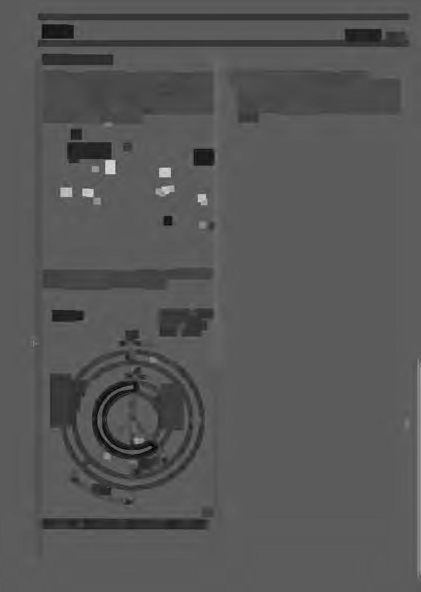
FIGURE 85

30
Aspirazione = Intake
P.M.S. = T.D.C.
Scarico = Exhaust
P.M.I. = B.D.C.
2791
8031I05-8041I05-8041SI25-8051I05
CAMSHAFT - BUSHES - TAPPETS 6 CYLINDERS
FIGURE 70
A
The camshaft support pin surfaces and cam lobe <;i_ •rfaces must be mirror smooth; if traces of seizing and sccring are detected, change the sf1aft and its bushes.
FIGURE 7·1
CAMSHAFT DETAILS
FIGURE 73
1~0)

Arrange the camshaft on two parallel blocks ( I ) and use a dial gauge (2) to check alignment of the support pins (3): misalignment should not exceed 0.020 rnm. If misalignment is greater t~1a:-. th:,t ~f;'J1·s, si.r a1gi ,te r1 the camshaft using a prPss
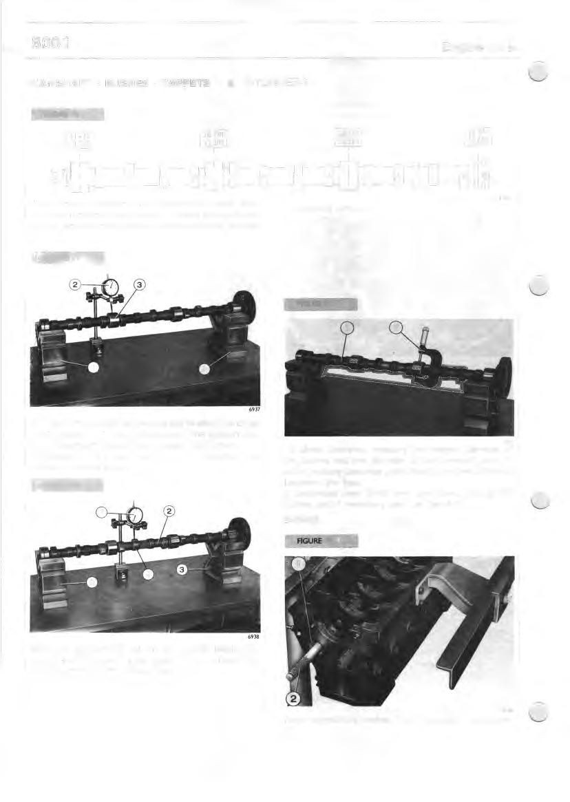
FIGURE 72
6939
To check clearance, measure the internal diameter of the bushes and the diameter of the camshaft pins ( I ); actual existing clearance is obtained from the difference between the two. If clearances over 0. I 60 mm are found, change the bushes and if necessary also the camshaft.
BUSHES
With the camshaft (2) still on the parallel blocks (3), check cam lift ( 4) with a dial gauge ( I ); this should be: o 5.955 mm fo~ the irtake lobe; IJ 6.027 ~r,m f::r the e;-,::,a.J,;t lohf:!
8138
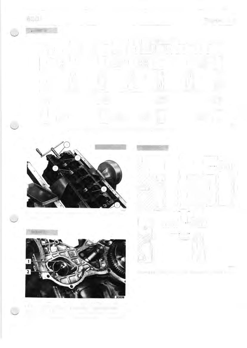
Removing/refitting bushes ( I ) of camshaft, using driver (2).
FIGURE 75
CAMSHAFT BUSH DETAILS AND THEIR HOUSINGS IN THE ENGINE BLOCK
FIGURE 78
69'40
Regrinding camshaft bushes with chuck ( I ), guide sleeve (2) and cutter (3). ,1.000.1 I 15,018
DETAILS OF TAPPETS AND THEIR HOUSINGS IN ENGINE BLOCK
NOTE - W hen fitting the bushes ( I ), pay attention to the location of the holes (2), which must be in line with those for the passage of lubricating oil in the engine block.