INTRODUCTION GENERAL
DESCRIPTION
This section has the description and repair procedures for the lift truck frame and connected parts. Included in this section are the frame, counterweight, fenders, hood, hydraulic and fuel tanks, radiator and operator compartment. The instructions for removal and installation of the engine are included in this section.
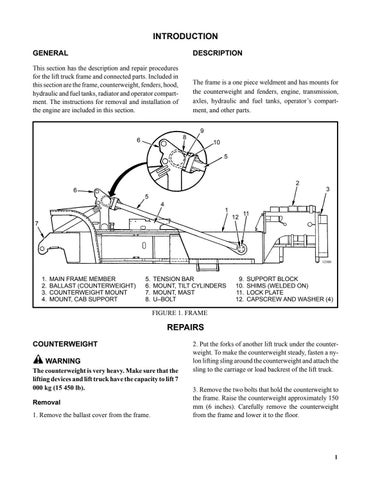
The frame is a one piece weldment and has mounts for the counterweight and fenders, engine, transmission, axles, hydraulic and fuel tanks, operator’s compartment, and other parts. 9 8
6
10 5
2 3
6 5 4 1 12
11
7
12500
1. 2. 3. 4.
MAIN FRAME MEMBER BALLAST (COUNTERWEIGHT) COUNTERWEIGHT MOUNT MOUNT, CAB SUPPORT
5. 6. 7. 8.
TENSION BAR MOUNT, TILT CYLINDERS MOUNT, MAST U–BOLT
9. 10. 11. 12.
SUPPORT BLOCK SHIMS (WELDED ON) LOCK PLATE CAPSCREW AND WASHER (4)
FIGURE 1. FRAME
REPAIRS COUNTERWEIGHT WARNING The counterweight is very heavy. Make sure that the lifting devices and lift truck have the capacity to lift 7 000 kg (15 450 lb). Removal 1. Remove the ballast cover from the frame.
2. Put the forks of another lift truck under the counterweight. To make the counterweight steady, fasten a nylon lifting sling around the counterweight and attach the sling to the carriage or load backrest of the lift truck. 3. Remove the two bolts that hold the counterweight to the frame. Raise the counterweight approximately 150 mm (6 inches). Carefully remove the counterweight from the frame and lower it to the floor.
1
