25 minute read
OPERATOR MANUAL


Supplement Crane Warm-up Procedures
© 2017 Manitowoc
Published 3-30-2017, Control # 516-04
An untrained operator subjects himself and others to death or serious injury. Do not operate this crane unless:
•You are trained in the safe operation of this crane. Manitowoc is not responsible for qualifying personnel.
•You read, understand, and follow the safety and operating recommendations contained in the crane manufacturer’s manuals and load charts, your employer’s work rules, and applicable government regulations.
•You are sure that all safety signs, guards, and other safety features are in place and in proper condition.
•The Operator Manual and Load Chart are in the holder provided on crane.
Section Contents
This Supplement provides information regarding the proper warm-up procedures for operating the crane in colder temperatures. The information provided here supplements the Operator and Service Manual s and must be used in conjunction with these manuals.
Cold Climate Engine Operation
Engine specific cold climate operation information is available through your Cummins dealer/service center under Service Bulletin 3379009.
CRANE WARM-UP PROCEDURES
The following procedures detail the actions that must be taken to properly warm the different crane components before operating the crane.
NOTE: For temperatures below -9°C (15°F) refer to arctic lubricants and conditions in the Operator and Service Manuals.
Before starting the crane, ensure the appropriate lubricants are used in order to provide lubrication for the prevailing ambient temperatures in which the crane will operate in (a list of lubricants and their temperature ranges can be found in the Lubrication section of your crane’s Operator Manual, by contacting your local Manitowoc distributor, or by contacting Manitowoc Crane Care directly).
Caution
Crane Damage Hazard!
Operating the crane with the incorrect lubricants and fluids for the prevailing ambient temperature and/or failing to adequately warm the crane prior to cold weather operation can lead to a failure of a crane component or system.
Always use Manitowoc recommended lubricants and fluids for the prevailing ambient temperature and properly start and warm the crane using the cold weather procedures found in this Operator Manual and supplement before operating the crane at full load.
Engine
Warm-up Procedures for All Temperature Ranges:
1. Upon startup, allow the engine to idle for 3 to 5 minutes before operating with a load.
2. Cold Engine Startup: After allowing the engine to warm by idling it for 3 to 5 minutes, slowly increase the engine speed to provide adequate lubrication to the bearings and to allow the oil pressure to stabilize.
Transmission
Operating the transmission with a sump temperature below normal operating temperature is limited to:
• operating in the neutral gear or
• driving with an unloaded crane while not exceeding 1500 engine RPM and not exceeding half throttle.
Warm-up Procedures for Rough Terrain (RT) and Industrial Cranes:
1. Engage the parking brake and apply the service brake.
2. Shift the transmission into the highest gear and increase the engine RPM to 1500 for 15 seconds, then allow the engine RPM to return to idle.
3. Repeat Step 2 until the temperature of the transmission sump reaches normal operating temperature.
Alternate Warm-up Procedures for Rough Terrain (RT) and Industrial Cranes:
1. Setup the crane on outriggers.
2. Engage the transmission with 4-wheel drive selected (if equipped) and allow crane to run at idle until the temperature of the transmission sump reaches normal operating temperature.
NOTE: Warm-up operation of 4-wheel drive transmission engaged in 2-wheel drive only could cause transmission damage.
Alternate Warm-up Procedures for Truck Mount (TM/ TMS) Cranes:
1. Setup the crane on outriggers.
2. Engage the transmission and allow crane to run at idle until the temperature of the transmission sump reaches normal operating temperature.
Hoist
Performing a warm-up procedure is recommended at every startup and is required at ambient temperatures below 4°C (40°F).
Warm-up Procedures:
1. Without operating the hoist function, warm the hydraulic oil (see Hydraulic Oil System, page 2-2).
2. Once the hydraulic system is warm, operate the unloaded hoist, in both directions, at low speeds several times to prime all hydraulic lines with warm hydraulic oil and to circulate gear lubricant through the planetary gear sets.
Swing Drive and Turntable Bearing
Warm-up Procedures for Temperatures Above -7°C (20°F):
1. Setup the crane on fully extended outriggers, with the boom fully retracted and near maximum lift angle with no load applied.
2. Rotate the superstructure at a speed of less than one RPM for at least one complete revolution in one direction, then rotate the superstructure at a speed of less than one RPM for at least one complete revolution in the opposite direction.
Warm-up Procedures for Temperatures Below -7°C (20°F):
1. Ensure the boom is fully retracted and near maximum lift angle with no load applied.
2. Rotate the superstructure at a speed of less than onehalf RPM for at least two complete revolutions in one direction, then rotate the superstructure at a speed of less than one-half RPM for at least two complete revolutions in the opposite direction.
Axles
Warm-up Procedures for Temperatures Below -35°C (-30°F):
1. Setup the crane on outriggers.
2. Engage the transmission (see Transmission, page 2-1) with 4-wheel drive selected (if equipped) and allow crane to run at idle until the temperature of the transmission sump reaches normal operating temperature.
NOTE: Warm-up operation of 4-wheel drive transmission engaged in 2-wheel drive only could cause transmission damage.
Hydraulic Oil System
Operating Limits and Warm-up Procedures:
•From 4°C to -10°C (40°F to 15°F): Crane operation without a load is allowed with medium engine RPM and medium function speed (joystick position) until the fluid reaches at least 10°C (50°F). It is then recommended that all crane functions be cycled to remove cold fluid from all components and cylinders of the hydraulic system. If there is any unusual sound coming from the crane’s hydraulic pumps or motors, stop the operation and engine immediately and contact a Manitowoc distributor.
•From 10°C to 4°C (50°F to 40°F): Crane operation with a load is allowed with medium engine RPM and medium function speed (joystick position) until the fluid reaches at least 10°C (50°F).
•From 95°C to 10°C (200°F to 50°F): Crane operation with a load is allowed with no restrictions.
•Above 95°C (200°F): No crane operation is allowed. Let the crane’s hydraulic oil cool by running the engine at idle with no functions actuated.
Warning
California Proposition 65
Breathing diesel engine exhaust exposes you to chemicals known to the State of California to cause cancer and birth defects or other reproductive harm.
•Always start and operate the engine in a well-ventilated area.
•If in an enclosed area, vent the exhaust to the outside.
•Do not modify or tamper with the exhaust system.
•Do not idle the engine except as necessary.
For more information, go to www.P65warnings.ca.gov/diesel Batteries, battery posts, terminals, and related accessories can expose you to chemicals, including lead and lead compounds, which are known to the State of California to cause cancer and birth defects or other reproductive har m. Wash hands after handling. For more information, go to www.P65warnings.ca.gov
California Spark Arrestor
Operation of this equipment may create sparks that can start fires around dry vegetation. A spark arrestor may be required. The owner/operator should contact local fire agencies for laws or regulations relating to fire prevention requirements.
The original language of this publication is English.
You must read and understand the Operator's Manual and the Load Chart before operating your new crane. You must also view and understand the supplied safety video. The Operator's Manual supplied with and considered part of your crane must be read and completely understood by each person responsible for assembly, disassembly, operation and maintenance of the crane.


Operator Manual
This manual has been prepared for and is considered part of -
RT540E
Crane Model Number
This Manual is divided into the following sections:
SECTION 1 INTRODUCTION
SECTION 2 SAFETY INFORMATION
SECTION 3 OPERATING CONTROLS AND PROCEDURES
SECTION 4 SET-UP AND INSTALLATION PROCEDURES
SECTION 5 LUBRICATION
SECTION 6 MAINTENANCE CHECKLIST
NOTICE
The crane serial number is the only method your distributor or the factory has of providing you with correct parts and service information.
The crane serial number is identified on the builder’s decal attached to the operator cab. Always furnish crane serial number when ordering parts or communicating service problems with your distributor or the factory.
DANGER
An untrained operator subjects himself and others to death or serious injury. Do not operate this crane unless:
•You are trained in the safe operation of this crane. Manitowoc is not responsible for qualifying personnel.
•You read, understand, and follow the safety and operating recommendations contained in the crane manufacturer’s manuals and load charts, your employer’s work rules, and applicable government regulations.
•You are sure that all safety signs, guards, and other safety features are in place and in proper condition.
1 2 3 4 5 6
Published
Rt540e Operator Manualtable Of Contents
See end of this manual for Alphabetical Index
Rt540e Operator Manualtable Of Contents
General
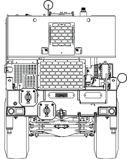
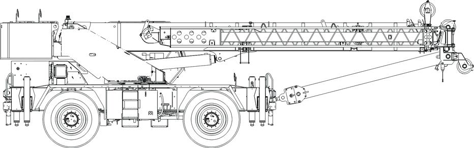
NOTE: Throughout this handbook, reference is made to left, front, and rear when describing locations. These reference locations are to be considered as those viewed from the operator seat with the superstructure facing forward over the front of the carrier frame.
This Manual provides important information for the operator of the Model RT540E Series Grove Crane.
The rough terrain crane incorporates an all welded steel frame, using planetary drive axles to provide four-wheel drive. Axle steering is accomplished utilizing hydraulic steer cylinders. The engine is mounted at the rear of the crane and provides motive power through a six speed forward and reverse transmission. Hydraulic, double box, sliding beam outriggers are integral with the frame.
The carrier frame incorporates an integral fifth wheel, to which the rear axle is mounted, to provide axle oscillation. Axle oscillation lockout is automatic when the superstructure rotates from the travel position.
The superstructure is capable of 360° rotation in either direction. All crane functions are controlled from the fullyenclosed cab mounted on the superstructure. The crane is equipped with a four-section cable synchronized full power boom. Additional reach is obtained by utilizing a swingaway boom extension. Lifting is provided by a main hoist and an optional auxiliary hoist.
NOISE/VIBRATION TEST RESULTS
Noise Level Test Results
• When equipped with the CE certification package, the guaranteed sound power levelat the operator’s station with closed cab operation, is L wa 105dB(A) as measured by Directive 2000/14/EC and 80db(A) at the crane operator position as measured by Annex G.1 of EN 13000:2010+A1:2014.
Vibration Level Test Results
• At the operator station with closed cab operation, vibration levels are less than 0.5 m/s/s for Whole Body Vibration exposure and are less than 2.5 m/s/s for Hand Arm Vibration exposure when measured according to 89/392/EEC Community Legislation on Machinery per standard ISO 2631/1 - Evaluation of Human Exposure to Work Body Vibration, ISO 5349 - Guidelines for the Measurement and Assessment of Human Exposure to Hand Transmitted Vibrations, and ISO/DIS 8041Human Response Vibration Measuring Instrumentation.
Customer Support
Manitowoc and our Distributor Network want to ensure your satisfaction with our products and customer support. Your local distributor is the best equipped and most knowledgeable to assist you for parts, service and warranty issues. They have the facilit ies, parts, factory trained personnel, and the information to assist you in a timely manner. We request that you first contact them for assistance. If you feel you need factory assistance, please ask the distributor’s service management to coordinate the contact on your behalf.
New Owners
If you are the new owner of a Grove crane, please register it with Manitowoc Crane Care so we have the ability to contact you if the need arises.
Go to: http://www.manitowoccranes.com/MCG_CARE/ Includes/EN/changeOfOwnership.cfm and complete the form.
List Of Specifications
NOTE: Dimensions listed are for a crane with all components fully retracted in the travel mode with 20.5 x 25-24 earthmover bias ply tires.
Swivel Assembly
Hydraulic Pumps
Pump #1
NOTE:
Transportation And Lifting Data Rt540e
1. LIFTING OF ENTIRE CRANE OR MAJOR CRANE ASSEMBLIES MUST BE ACCOMPLISHED BY UTILIZING SPECIFIC FITTINGS INDICATED ON ABOVE CHART. USE OF FITTINGS FOR PURPOSES OTHER THAN THOSE DESIGNATED ON CHART IS PROHIBITED. FITTING CAPACITIES ARE MAXIMUM ALLOWABLE LOADS PER INDIVIDUAL FITTING.
2. RIGGING PERSONNEL SHALL BE RESPONSIBLE FOR PROPER SELECTION AND PLACEMENT OF ALL SLINGS AND LOAD HANDLING DEVICES.
3. DIMENSIONS AND WEIGHTS SHOWN ARE FOR HEAVIEST CONFIGURATION AVAILABLE.
4. RIGGING PERSONNEL SHALL VERIFY DIMENSIONS AS REQUIRED FOR CLEARANCE.
5. EXTEND OUTRIGGER BEAMS 46 CM (18 IN) AND SLING AROUND BEAMS.
6. DO NOT USE PINTLE HOOKS OR CWT LUGS FOR LIFTING OR TIE DOWN OF ENTIRE CRANE.
Serial Number Location
Refer to Figure 1-2 for the locations of the crane serial number.

Published 01-15-2016, Control # 526-01

Section 2
SAFETY MESSAGES General
The importance of safe operation and maintenance cannot be overemphasized. Carelessness or neglect on the part of operators, job supervisors and planners, rigging personnel, and job site workers can result in their death or injury and costly damage to the crane and property.
To alert personnel to hazardous operating practices and maintenance procedures, safety messages are used throughout the manual. Each safety message contains a safety alert symbol and a signal word to identify the hazard’s degree of seriousness.
Safety Alert Symbol
This safety alert symbol means ATTENTION! Become alert - your safety is involved! Obey all safety messages that follow this symbol to avoid possible death or injury.
Signal Words
Danger
Identifies hazards that will result in death or serious injury if the message is ignored
WARNING
Identifies hazards that may result in death or serious injury if the message is ignored. CAUTION
Identifies hazards that could result in minor or moderate injury if the message is ignored.
Caution
Without the safety alert symbol, identifies hazards that could result in property damage if the message is ignored.
NOTE: Emphasizes operation or maintenance procedures.
General
It is impossible to compile a list of safety precautions covering all situations. However, there are basic principles that must be followed during your daily routine. Safety is your primary responsibility, since any piece of equipment is only as safe as the person at the controls
Read and follow the information located in Model Specific Information near the end of this section.
This information has been provided to assist in promoting a safe working atmosphere for yourself and those around you. It is not meant to cover every conceivable circumstance which could arise. It is intended to present basic safety precautions that should be followed in daily operation.
Because you are the only part of the crane that can think and reason, your responsibility is not lessened by the addition of operational aids or warning devices. Indeed, you must guard against acquiring a false sense of security when using them. They are there to assist, not direct the operation. Operational aids or warning devices can be mechanical, electrical, electronic, or a combination thereof. They are subject to failure or misuse and should not be relied upon in place of good operating practices.
You are the only one who can be relied upon to assure the safety of yourself and those around you. Be a professional and follow the rules of safety
Remember, failure to follow just one safety precaution could cause an accident that results in death or serious injury to personnel or damage to equipment. You are responsible for the safety of yourself and those around you.
Warning Signs
Refer to the Parts Manual for a drawing indicating the location of warning signs on the crane.
Accidents
Following any accident or damage to equipment, the Manitowoc dealer must be immediately advised of the incident and consulted on necessary inspections and repairs. Should the dealer not be immediately available, contact should be made directly with Manitowoc Product Safety at the address below. The crane must not be returned to service until it is thoroughly inspected for any evidence of damage. All damaged parts must be repaired or replaced as authorized by your Manitowoc distributor and/or Manitowoc Crane Care.
If this crane becomes involved in a property damage and/or personal injury accident, immediately contact your Manitowoc distributor. If the distributor is unknown and/or cannot be reached, contact Product Safety at:
The Manitowoc Company, Inc.
1565 East Buchanan Trail Shady Grove, PA 17256-0021
Phone:888-777-3378 (888-PSR.DEPT)
717-597-8121
Fax:717-593-5152
E-mail:product.safety@manitowoc.com
Operator Information
You must read and understand this Operator Manual and the Load Chart before operating your new crane. You must also view and understand the supplied safety video. This manual and Load Chart must be readily available to the operator at all times and must remain in the cab (if equipped) or operator’s station while the crane is in use.
The Operator Manual supplied with and considered part of your crane must be read and completely understood by each person responsible for assembly, disassembly, operation and maintenance of the crane.
No personnel shall be allowed to climb onto the crane or enter the crane cab or operator’s station unless performance of their duties require them to do so, and then only with knowledge of the operator or other qualified person.
Allow No One other than the operator to be on the crane while the crane is operating or moving, unless they are seated in a two-man cab.
be thoroughly familiar with the location and content of all placards and decals on the crane. Decals provide important instructions and warnings and must be read prior to any operational or maintenance function.


Refer to the Parts Manual for this crane for the locations of all safety decals.
You must be familiar with the regulations and standards governing cranes and their operation. Work practice requirements may vary slightly between government regulations, industry standards, and employer policies so a thorough knowledge of all such relevant work rules is necessary.
Do not remove the Load Chart , this Operator Manual , or any decal from this crane.
Inspect the crane every day (before the start of each shift). Ensure that routine maintenance and lubrication are being dutifully performed. Don’t operate a damaged or poorly maintained crane. You risk lives when operating faulty machinery - including your own.
If adjustments or repairs are necessary, the operator shall notify the next operator.
Operator Qualifications
Qualified person is defined as one who by reason of knowledge, training and experience is thoroughly familiar with crane operations and the hazards involved. Such a person shall meet the operator qualifications specified in Occupational Safety and Health Administration (OSHA) Regulations (United States Federal Law), in ASME B30.5 American National Standard, or in any other applicable federal, state or local laws.
Ensure that all personnel working around the crane are thoroughly familiar with safe operating practices. You must
An untrained operator subjects himself and others to death or serious injury.
You must not operate this crane unless:
• You have been trained in the safe operation of this crane.
• You read, understand, and follow the safety and operating recommendations contained in the manufacturer’s manuals, your employer’s work rules, and applicable government regulations.
• You are sure the crane has been inspected and maintained in accordance with the manufacturer’s manuals and is operating properly.
• You are sure that all safety signs, guards, and other safety features are in place and in proper condition.
Do not attempt to operate the crane unless you are trained and thoroughly fam iliar with all operati onal functions. Controls and design may vary from crane to crane; therefore, it is important that you have specific training on the particular crane you will be operating.
Training is ESSENTIAL for pro per crane oper ation. Never jeopardize your own well-being or that of others by attempting to operate a crane on which you have not been trained.
You must be mentally and physically fit to operate a crane. Never attempt to operate a crane while under the influence of medication, narcotics, or alcohol. Any type of drug could impair physical, visual and mental reactions, and capabilities.
As operator of this crane, you are granted the authority to stop and refuse to lift loads until safety is assured.
Operational Aids
Operational aids are accessories that provide information to facilitate operation of a crane or that take control of particular functions without action of the operator when a limiting condition is sensed, as stated in the latest revision of the ASME B30.5, and ASME B30.8 standards. Examples of such devices include, but are not limited to, the following: anti-two-block device, rated capacity indicator, rated capacity limiter, boom angle or radius indicator, boom length indicator, crane level indicator, hoist drum rotation indicator, load indicator, and wind speed indicator.
Manitowoc remains committed to providing reliable products that enable users and operators to safely lift and position loads. Manitowoc has been an industry leader in the incorporation of operational aids into the design of its cranes. Federal law requires that cranes be properly maintained and kept in good working condition. The manuals that Manitowoc provides that are specific for each crane and the manufacturer’s manuals for the operational aids shall be followed. If an operational aid should fail to work properly, the crane user or owner must assure that repair or recalibration is accomplished as soon as is reasonably possible. If immediate repair or recalibration of an operational aid is not possible and there are exceptional circumstances which justify continued short-term use of the crane when operational aids are inoperative or malfunctioning, the following requirements shall apply for continued use or shutdown of the crane:
• Steps shall be taken to schedule repairs and recalibration immediately. The operational aids shall be put back into service as soon as replacement parts, if required, are available and the repairs and recalibration can be carried out. Every reasonable effort must be made to expedite repairs and recalibration.
• When a Load Indicator, Rated Capacity Indicator, or Rated Capacity Limiter is inoperative or malfunctioning, the designated person responsible for supervising the lifting operations shall establish procedures for determining load weights and shall ascertain that the weight of the load does not exceed the crane ratings at the radius where the load is to be handled.
• When a Boom Angle or Radius Indicator is inoperative or malfunctioning, the radius or boom angle shall be determined by measurement.
• When an Anti-Two-Blocking Device, Two-Blocking Damage Prevention Device or Two-Block Warning Device is inoperative or malfunctioning, the designated person responsible for supervising the lifting operations shall establish procedures, such as assigning an additional signal person to furnish equivalent protection. This does not apply when lifting personnel in load-line supported personnel platforms. Personnel shall not be lifted when anti-two-block devices are not functioning properly.
• When a Boom Length Indicator is inoperative or malfunctioning, the designated person responsible for supervising the lifting operations shall establish the boom lengths at which the lift will be made by actual measurements or marking on the boom.
• When a Level Indicator is inoperative or malfunctioning, other means shall be used to level the crane.
Rated Capacity Limiter (RCL) Systems (If Equipped)
Your crane may be equipped with an RCL system which is intended to aid the operator. An RCL is a device that automatically monitors radius, load weight, and load rating and prevents movements of the crane, which would result in an overload condition.
Test daily for proper operation. Never interfere with the proper functioning of operational aids or warning devices.
Under no condition should it be relied upon to replace the use of Load Charts and operating instructions. Sole reliance upon these electronic aids in place of good operating practices can cause an accident.
Know the weight of all loads and always check the capacity of the crane as shown on the Load Chart before making any lifts.
NEVER
exceed the rated capacity shown on the Load Chart
Always check the Load Chart to ensure the load to be lifted at the desired radius is within the rated capacity of the crane.
For detailed information concerning the operation and maintenance of the RCL system installed on the crane, see the RCL manufacturer’s manual supplied with the crane. Manufacturers of rated capacity limiters may refer to them in their manuals as a load moment indicator (LMI), a hydraulic capacity alert system (HCAS), a safe load indicator (SLI), or an EKS5; Manitowoc refers to these systems as a rated capacity limiter (RCL) throughout its Operator and Service Manuals
Anti-Two-Blocking Device
This crane should have a functional Anti-Two-Block and Control Lock-Out System. Test daily for proper operation.
Two-blocking occurs when the load block (hook block, headache ball, rigging, etc.) comes into physical contact with the boom (boom nose, sheaves, jib, etc.). Two-blocking can cause hoist rope (wire rope or synthetic rope), rigging, reeving, and other components to become highly stressed and overloaded in which case the hoist rope may fail allowing the load, block, etc. to free fall.
Two-blocking is more likely to occur when both the main and auxiliary hoist lines are reeved over the main boom nose and jib nose respectively. An operator, concentrating on the specific line being used, may telescope or lower the boom allowing the other hoist line attachment to contact the boom or jib nose, thus causing damage to the sheaves, or causing the hoist rope to fail, dropping the lifting device to the ground and possibly injuring personnel working below.
Caution must be used when lowering the boom, extending the boom or hoisting up. Let out load line(s) simultaneously to prevent two-blocking the boom tip(s) and the hook block, etc. The closer the load is carried to the boom nose the more important it becomes to simultaneously let out hoist rope as the boom is lowered. Keep load handling devices a minimum of 107cm (42in) below the boom nose at all times.

Two-blocking can be prevented. Operator awareness of the hazards of two-blocking is the most important factor in preventing this condition. An Anti-Two-Block System is intended to assist the operator in preventing dangerous twoblock conditions. It is not a replacement for operator awareness and competence.
Never interfere with the proper functioning of operational aids or warning devices.
Working Area Limiter (If Equipped)
This crane may be equipped with a working area limiter as part of the RCL system, designated as either Work Area Definition System (WADS) or Working Range Limiter (WRL). You must read and understand the operator manual before operating the working area limiter system. Become familiar with all proper operating procedures and with the identification of symbol usage.
The working area limiter is intended to be used as an aid to the operator. It is not a substitute for safe crane operating practices, experience and good operator judgements.
CRANE STABILITY/STRUCTURAL STRENGTH
To avoid death or serious injury, ensure that the crane is on a firm surface with load and crane’s configuration within capacity as shown on the crane’s Load Chart and notes. must be properly extended and set to provide precise leveling of the crane. Tires must be clear of the ground before lifting on outriggers.
Ensure all pins and floats are properly installed and outrigger beams are properly extended before lifting on outriggers. On models equipped with outriggers that can be pinned at the mid-extend position (vertical stripe, if applicable), the outriggers must also be pinned when operating from the midextend position.
Use adequate cribbing under outrigger floats to distribute weight over a greater area. Check frequently for settling.
Read and follow the following safety decal for cranes with center front stabilizers.

Carefully follow the procedures in this Operator Manual when extending or retracting the outriggers. Death or serious injury could result from improper crane setup on outriggers.
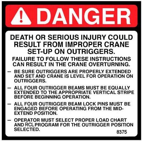
The operator must select the proper Load Chart and Rated Capacity Limiter (RCL) System program for the outrigger position selected.
Before swinging the superstructure over the side when the outriggers are retracted, check the Load Chart for backwards stability.
Long cantilever booms can create a tipping condition when in an extended and lowered position. Retract the boom proportionally with reference to the capacity of the applicable Load Chart
Check crane stability before lifting loads. Ensure the outriggers (or tires if lifting on rubber) are firmly positioned on solid surfaces. Ensure the crane is level, brakes are set, and the load is properly rigged and attached to the hook. Check the Load Chart against the weight of the load. Lift the load slightly off the ground and recheck the stability before proceeding with the lift. Determine the weight of the load before you attempt the lift.
Unless lifting within On Rubber capacities, outrigger beams and jack cylinders (plus center front stabilizer, if equipped)
KEEP THE BOOM SHORT. Swinging loads with a long line can create an unstable condition and possible structural failure of the boom.
Load Charts
Load Charts represent the absolute maximum allowable loads, which are based on either tipping or structural limitations of the crane under specific conditions. Knowing the precise load radius, boom length, and boom angle should be a part of your routine planning and operation. Actual loads, including necessary allowances, should be kept below the capacity shown on the applicable Load Chart
Load Chart capacities are based on freely suspended loads. You must use the appropriate Load Chart when determining the capability of the crane in the configuration required to perform the lift.
Maximum lifting capacity is available at the shortest radius, minimum boom length, and highest boom angle.
Do not remove the Load Charts from the crane.
Work Site
Prior to any operation, you must inspect the entire work site, including ground conditions, where the crane will travel and operate. Be sure that the surfaces will support a load greater than the crane’s weight and maximum capacity.
Be aware of all conditions that could adversely effect the stability of the crane.
Be aware of the danger for people entering the working area. Do not allow unnecessary personnel in the vicinity of the crane while operating.
Wind Forces
There are basic principles th at must be followed while operating in windy conditions. This information has been provided to assist in determining safe operation in windy conditions.
Always use extreme caution wh en windy conditions exist. NEVER exceed the rated capacity shown on the Load Chart
Always check the Load Chart to ensure the load to be lifted is within the rated capacity of the crane.
Wind can have a significant effect on loads that may be lifted by a crane. Wind forces act differently on a crane depending upon the direction from which the wind is blowing (e.g., wind on the rear of the boom can result in decreased forward stability, wind on the underside of the boom can result in decreased backward stability, wind on the side of the boom can result in structural damages, etc.)
Wind forces can exert extreme dynamic loads. Manitowoc recommends that a lift not be made if the wind can cause a loss of control in handling the load.
Wind forces can be determined by typical visible effects on the landscape.To assist you in determining prevailing wind conditions, refer to Table 2-1.
NOTE: The wind speed corresponding to the Beaufort scale in the table is mean wind speed at 10m (33ft) elevation over a period of 10 minutes.
1Light
Wind felt on exposed skin. Leaves rustle. Wind vanes begin to move. 3 and small twigs constantly moving. Light flags extended.
4 of a moderate size move. Small trees in leaf begin to sway. branches in motion. Whistling heard in overhead wires. Umbrella use becomes difficult. Empty plastic bins tip over. 7High trees in motion. Effort needed to walk against the wind. 8Gale20.774.546.3
Gale24.487.854.6
Some branches break off trees, and some small trees blow over. Construction/temporary signs and barricades blow over.
10Storm28.4102.263.5Trees
Wind Speeds
wind speed recorded at crane operation site. For lift planning purposes only, the 3-second wind gust speed, V(z), may be calculated based on mean wind speed reported at http:// www.windfinder.com “Super Forecast”.
This 3-second wind gust is assumed to act on the entire crane and the load. The wind effect on the load can be conservatively estimated as: a) If V(z) is ≤ 13.4m/s (30mph), then the allowable load is the published rated capacity from the Load Chart. b) If V(z) is >13.4m/s (30mph) and is ≤ 20.1m/s (45mph), the allowable load is the published rated capacity multiplied by th e Capacity Reduction Factor from Table 2-4 (metric) or Table 2-6 (non-metric). c) If V(z) is >20.1m/s (45mph), then lifting is NOT permitted. Cease lifting operations and lower and retract the boom.
NOTE: This condition is limited to operation with the main boom on fully extended outriggers only.
In both cases a) and b) above, the lift may also be limited by the projected wind area of the load Ap and by the wind drag coefficient Cd : This limit can be determined by comparing the Actual wind resistance area with the Allowable wind resistance area.
Refer to Figure2-2 for a simplified calculation method to determine permissible wind speed.
Simplified Method to Determine Maximum Permissible Wind Speed

Determination of 3-second wind gust speed at boom tip height:
The following example illustrates how to calculate 3-second wind gust speed at boom tip height based on mean wind speed recorded by the device located at the crane operation site:
V(z) is the 3-second wind gust speed at boom tip height Z then:
Metric, with Z [m] and V [m/s]
V(z) =[(Z/10)0.14 + 0.4] x V (2.1)
Non-metric, with Z [ft] and V [mph]
V(z) =[(Z/33)0.14 + 0.4] x V (2.2) where:
V [m/s] [mph] - Mean wind speed at 10m(22ft) elevation (upper limit of Beaufort scale)
Example : Suppose you want to lift the load with the maximum boom tip height of 30m (100ft) and the recorded mean wind speed by the device located at the crane operation site is 5.5m/s (13mph). This mean wind speed of 5.5m/s (13mph) corresponds to Beaufort number 4 (see Table 2-1). The maximum wind velocity according to the Beaufort scale of 4 is 7.9m/s (17.7mph).
The mean wind speed (upper limit of Beaufort number) at 10m (33ft) height, to be used for calculation is:
V =7.9m/s (17.7mph)
Boom tip height for this lift is Z = 30m (100ft) then:
Metric, with Z [m] and V [m/s]
V(z) =[(30/10)0.14 +0.4]x7.9= 12.4m/s
Non-metric, with Z [ft] and V [mph]
V(z) =[(100/33)0.14 +0.4]x17.7=27.8mph
Since V(z) is ≤ 13.4m/s (30mph), the allowable loads are the published rated capacities from the Load Chart and can be lifted at this condition.
Size and Shape of the load:
These rated capacities are also based on the assumption that the Wind Resistance Area of load, Awr(load) is not more than 0.0012square meters per kilogram (0.0059 sq.ft per pound of load. (See below Formulas 2.4 and 2.5.)
The load capacities shall be reduced to account for the larger wind resistance area of load and 3-second wind gust speed at boom tip height. Use tag lines when the wind gust speed is above 13.4 m/s (30mph) to help control the movement of the load. Manitowoc recommends that a lift not be made if the wind can cause a loss of control in handling the load.
The lift may also be limited by the projected wind area of the load Ap and by the wind drag coefficient Cd. This limit can be determined by comparing the actual wind resistance area of the load with the allowable wind resistance area.
Awr(load) = Ap x Cd (2.3) where:
Awr(load) [m2] [ft2] .- Wind resistant area of the load
Ap [m2] [ft2] - projected wind area, Cd - wind drag coefficient.
Ap is determined by using the calculation of maximum height x maximum length (see Figure2-3).
For Cd, refer to Table 2-2. If the Cd cannot be calculated or estimated, use a value of 2.4.
The allowable wind resistant area of the load Awr (allow) is equal to 0.0012 square meters per kilogram (0.0059 sq.ft per pound) of allowable load:
Metric, with m(load) [kg] - Mass of the allowable load
Awr(allow) =0.0012 × m(load) (2.4)
Non-metric, with m(load) [lb] - Mass of the allowable load
Awr(allow) =0.0059 × m(load) (2.5)
If Awr(load) is greater than Awr(allow), then lifting this load at this wind speed V(z) is NOT permitted.
Calculation of Projected Wind Area (Ap):
Determining Wind Drag Coefficient (Cd)
Table 2-2 shows the typical Shapes and corresponding Wind Drag Coefficient (Cd) values.
If the exact Wind Drag Coefficient of a shape is not known, use the maximum value of the shape’s range (Table 2-2).

If the wind drag coefficient of the load cannot be estimated or determined, it shall be assumed that (Cd)= 2.4
Table 2-2 Wind Drag Coefficient Maximum Permissible Wind Speed
If the wind resistant area of the load Awr(load) is greater than the allowable wind resistant area Awr(allow), the ratio can be used to determine a permissible wind speed V(z) for the load using Table 2-3.

Note: Permissible and rated wind speeds in this table are the 3-second gust wind speeds at boom tip height.
Published 01-15-2016, Control # 526-01