
8 minute read
CHAPTER 3 SAFETY EQUIPMENT


Become familiar with all safety devices on the machine before starting. Know how to stop the machine before starting it. The machine is designed and intended to be used only with Manitou Group-approved attachments or accessories. Manitou Group cannot be responsible for operator safety if the machine is used with unapproved attachments.
Guards and Shields
Guards and shields are provided on the machine, wherever possible without effecting machine operation, to protect against potential hazards. In many places, safety decals are also provided to warn of potential hazards and/or to display special operating procedures.
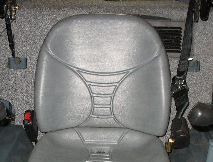
Use lever (A, Figure 4)to move the seat forward or back as desired. Release handle (A) when the seat is in the desired position. Make sure the seat is locked in position after adjusting.
Seat suspension
Seat suspension can be adjusted as necessary to compensate for the drivers weight and preferred seat suspension stiffness.
Read and thoroughly understand all safety decals before operating the machine. Do not operate the machine unless all factory-installed guards and shields are properly installed and secured in place.
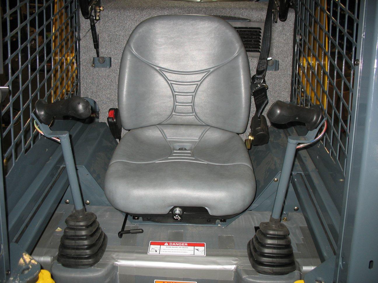
Operator’s Position
Operator’s Seat
Never adjust the seat during machine operation. Adjust the seat only when the machine is stopped and the restraint bar is in the raised position. After adjustments, make sure the seat is securely locked in place before using the machine.
Horizontal adjustment: The seat is mounted on rails to allow forward and back horizontal position adjustment.
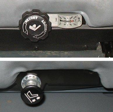
Mechanical suspension: While sitting in the operator’s seat, rotate knob (Z, Figure 5) as necessary to adjust seat suspension so weight indicator (X) is set to the approximate weight of the operator.
Air Suspension (option): Use knob (V) to adjust air suspension as desired.
Seat Belt
Always fasten the seat belt before operating the machine and keep it fastened during machine operation.
Repair or replace any damaged seat belt and clasp parts before operating the machine. Do not operate the machine if the seat belt is not fastened and working properly. After an accident, the seat belt strap is stretched and must be replaced with a new strap installed by an authorized dealer.
Important: Keep seat belt(s) clean. Use only soap and water to wash seat belt(s); cleaning solvents can damage the seat belt(s).
Fastening/ Unfastening the Seat Belt
Remove hard, edged or fragile objects from your pockets or clothes that might lie between the seat belt and your body. Fasten the seat belt around your hips and waist and insert tongue (F, Figure 6) into clasp (G) until it clicks securely in place. Slack in the seat belt should automatically retract into seat belt spool (H). Make sure the seat belt is not twisted when it is fastened, and that it is fastened over the hips and not the stomach. Unfasten the seat belt by pressing button (I).
If the seat belt spool does not retract the slack in the seat belt, have it serviced immediately. Repair or replace any damaged seat belt and lock parts before operating the machine.
Upper Torso Restraint (Option)
Always wear the upper-torso restraint (J, Figure 6) when operating in high speed.
The seat belt should always be fastened during operation.
Important: Inspect the seat belt(s) for damage before use, and replace if damaged. Keep seat belt(s) clean. Use only soap and water to wash seat belt(s). Cleaning solvents can cause damage to seat belt(s).
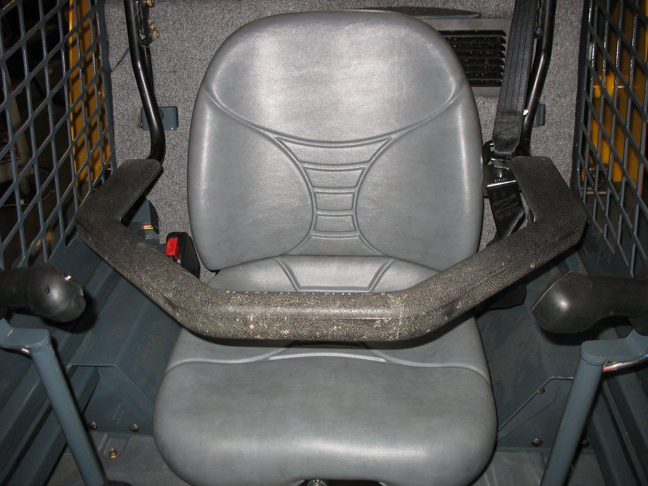
Operator Restraint Bar
Lower operator restraint bar (C, Figure 7) after entering the operator’s compartment and sitting in the seat. The restraint bar is securely anchored to the ROPS/FOPS. The operator must be seated with the restraint bar in its lowered position to start or operate the machine. The position of the restraint bar in the lowered position can be adjusted. To adjust:
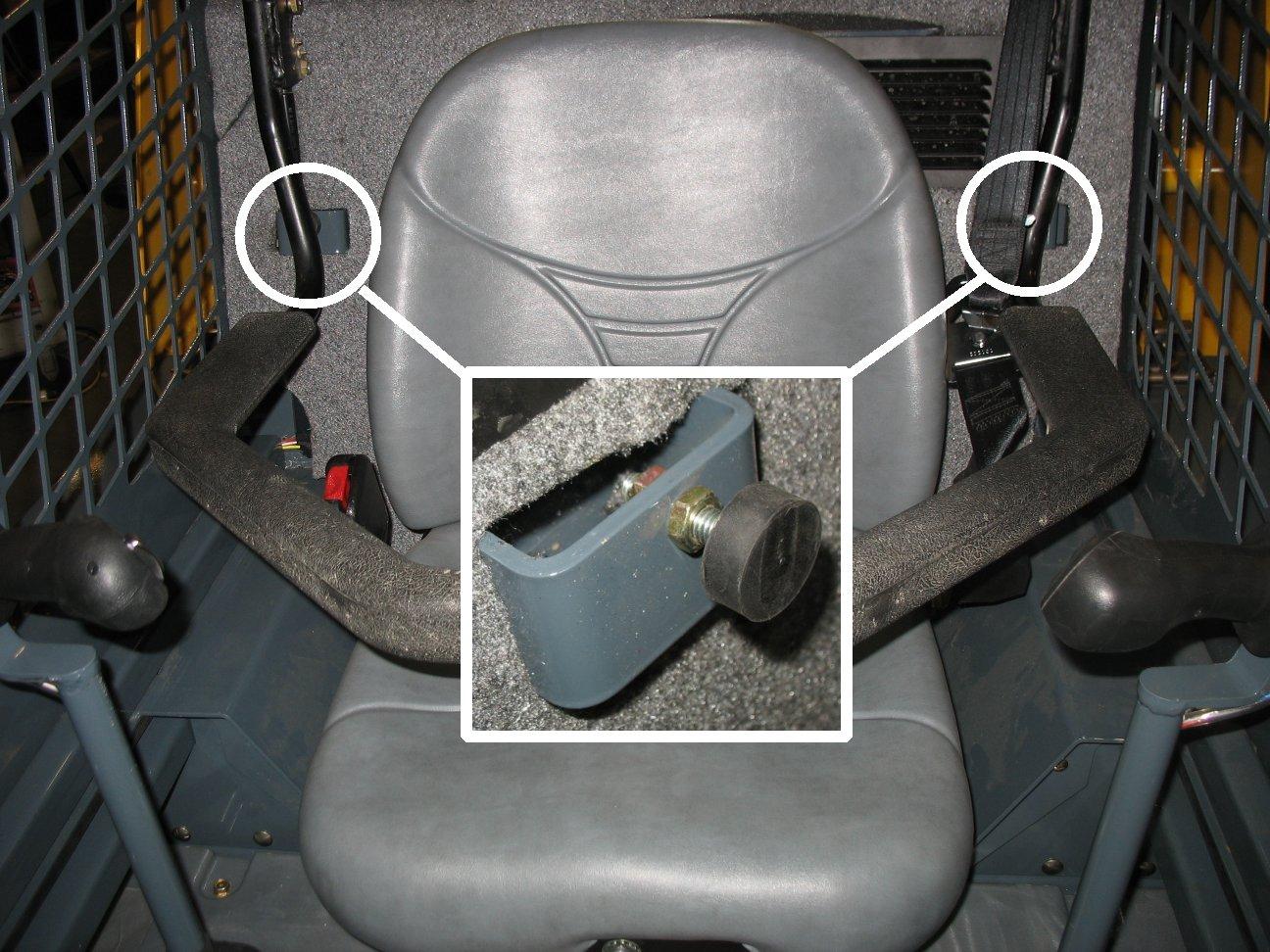
Loosen jam nut (D, Figure 8), and rotate rubber stop (E) in or out to the desired position. Tighten jam nut (D) to lock rubber stop (E) in position.
Important: Make sure rubber stops (E) are adjusted evenly.
Never electrically or mechanically defeat the operator restraint bar or seat switch.
Safety Interlock System (Hydraloc™)
NEVER attempt to bypass or defeat the safety interlock system. Serious personal injury or death could result.
The Hydraloc™ safety interlock system provides for operator safety. The interlock system:
•Prevents the engine from starting unless the operator is sitting in the operator’s seat with the restraint bar lowered.
•Disables the lift arm, auxiliary hydraulics, attachment tilt and wheel drive hydraulics if the restraint bar is raised, the ignition keyswitch is turned off or the operator’s seat is not occupied.
Note: Once started, the auxiliary hydraulic circuit will stay detented in the “on” position for continuous operation with the restraint bar raised and operator out of the seat. See“Auxiliary Hydraulic System” on page54.
Safety Interlock System Test
Each time before using the machine, check the safety interlock system daily for proper operation:
Seat Switch Test
With the engine off and the restraint bar lowered, unfasten the seat belt, and lift your weight off the seat. Try to start the engine. If the engine starts, turn off the engine, troubleshoot and correct the problem. Contact your dealer if necessary.
Restraint Bar Test
With the engine running, raise the restraint bar. Test each of the controls. The lift arm, hitch and drive should move only slightly. If there is any significant movement, troubleshoot and correct the problem immediately. Contact your dealer if necessary.
Parking Brake
The machine is equipped with a spring-applied, hydraulicallyreleased parking brake. The parking brake is automatically applied when the restraint bar is lifted, the operator’s seat is not occupied, or the engine is shut off. The brake can also be applied manually by pressing button (K, Figure 9) on the control keypad on the right door pillar.
Button (K) illuminates when the ignition keyswitch is in the ON/RUN position and the parking brake is applied.
ROPS/FOPS
The ROPS/FOPS (Roll-Over/Falling Object Protective Structure) is designed to protect the operator from falling objects and during a tip-over accident, if the operator is secured inside the operator’s compartment by the seat belt and restraint bar.
Warning
Never operate the machine with the ROPS/FOPS raised or removed.
Rear Window Emergency Exit
To use the emergency exit function, pull on yellow warning tag (M, Figure 10) at the top of the windowandremove the seal. Push or kickoutthewindow to allow exit from the machine.
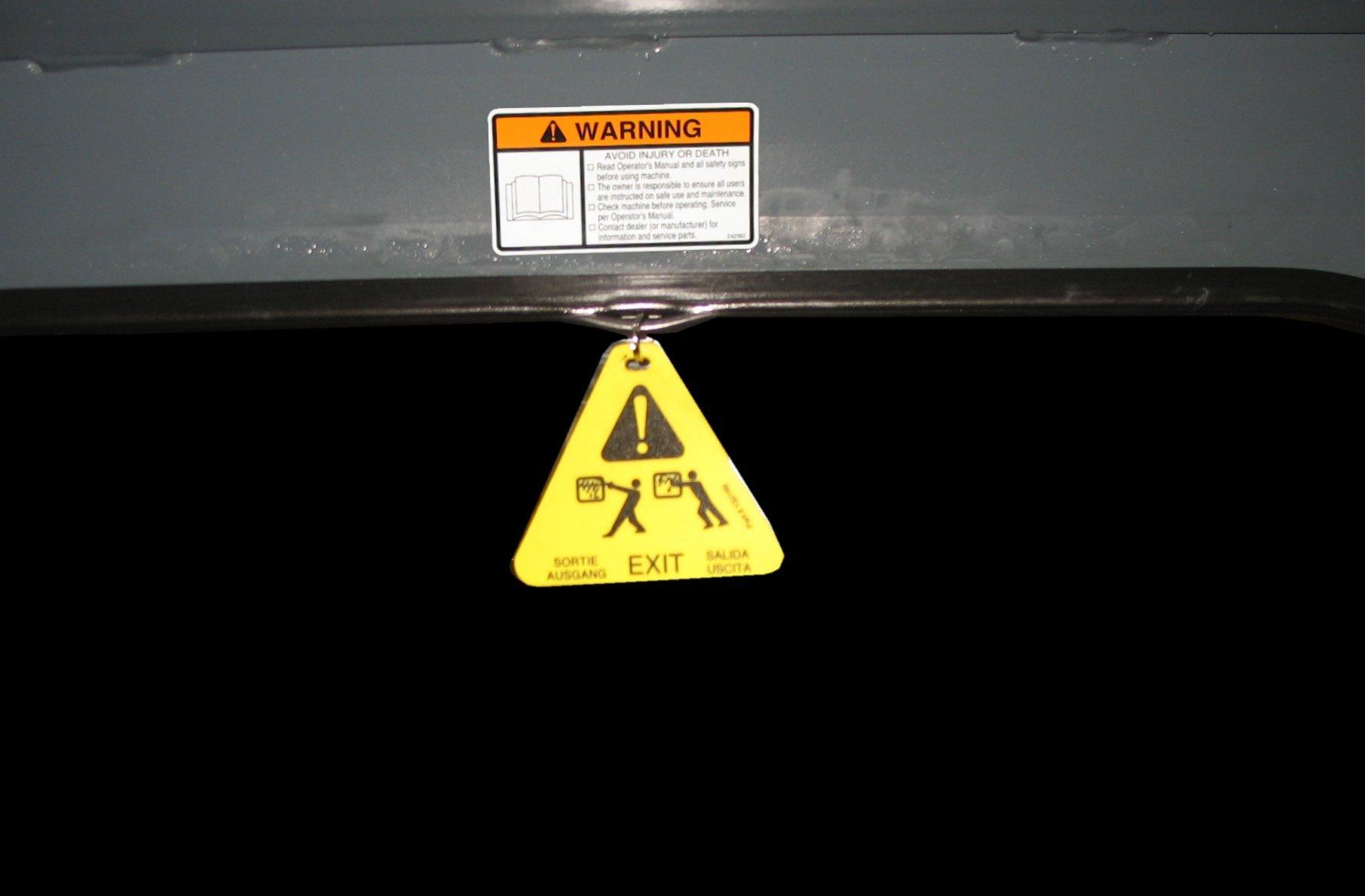
50950503/E0521 to reinstall the window, see your local automotive glass specialist.
Lift Arm Support
The lift arm support prevents the raised lift arm from lowering unexpectedly. The lift arm support must be applied whenever the lift arm is left in the raised position.
Warning
A falling lift arm could result in severe injury or death. Never allow anyone under a raised lift arm without the lift arm support applied.
If the lift arm must be left in the raised position, BE SURE to properly apply the lift arm support.
The operator must not leave the operator's position if the lift arm is in the raised position unless the lift arm support is properly applied.
Applying and disengaging the lift arm support requires two people – one person inside the machine and another person outside the machine to apply and/or disengage the support device.
The lift arm support must be kept in proper operating condition at all times.
Important: A second person on the outside of the machine is required to assist with applying the lift arm support.
Engage Lift Arm Support
1.Empty and remove the attachment (See “Connecting Attachments” on page64).
2.Bring the machine to a complete stop on a level surface.
3.Lower the lift arm fully.
4.Stop the engine.
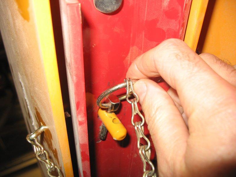
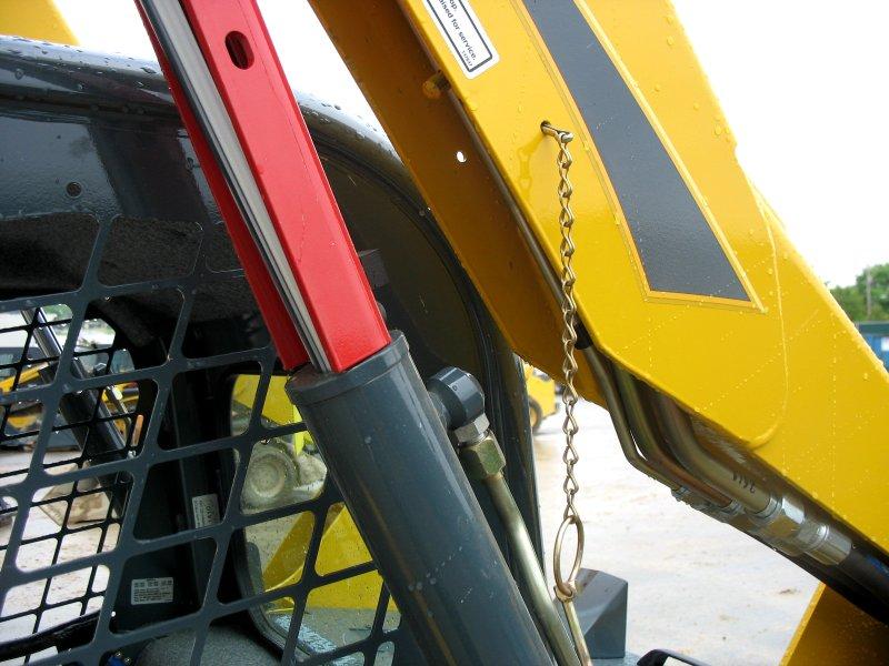
5.Have an assistant remove the lift arm support from its storage location on the left side of the machine. Remove lynchpin (S, Figure 11) holding lift arm support (T) up against the lift arm. Allow lift arm support (T) device to pivot down into contact with the lift cylinder.
6.Restart the engine.
7.Use the lift control to raise the lift arm until lift arm support (T, Figure 12) drops over the end of the lift cylinder and around the cylinder rod.
8.Slowly lower the lift arm until the free end of the support device contacts the top end of the lift cylinder (U).
9.Check the support device to ensure it is secure against the cylinder end.
10.Stop the engine.
11.Move the lift control to verify the control does not cause the lift arm to move.
12.Unfasten the seat belt, remove the ignition key and take it with you. Exit the machine using the hand-holds.
Disengage Lift Arm Support
Warning
The safest method of installing and removing the lift arm support device requires two people – one person inside the machine and another person outside the machine to disengage the support device.
1.Start the engine.
2.Raise the lift arm fully.
3.Stop the engine.
4.Verify that the lift arm is being held in the raised position by the safety interlock system.
Important: With the key switch OFF and the solenoid valve working properly, the lift arm will stay raised when the lift control is moved to lower the lift arm. If the valve does not hold the lift am and it begins to lower do not leave the operator’s compartment. Instead, lower the lift arm against the lift arm support and exit the machine. Then, contact your dealer immediately to determine why the lift arm lowers while the key switch is OFF.
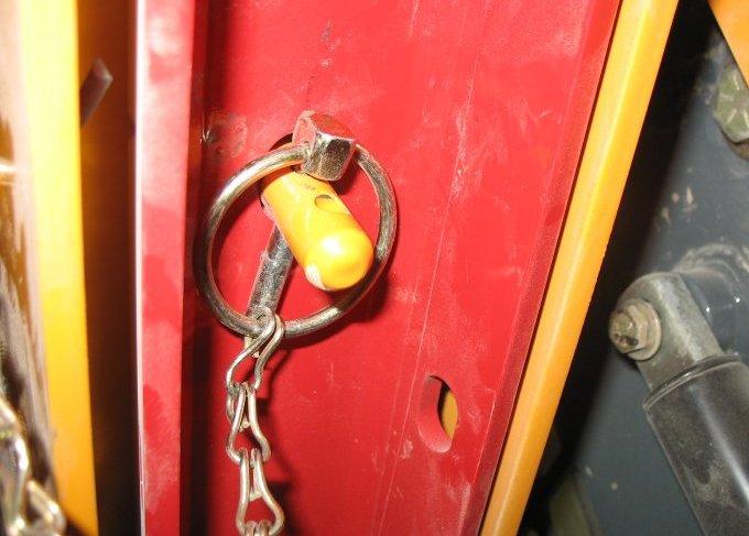
5.Have an assistant raise lift arm support (T, Figure 13) until it contacts the lift arm. Reinstall lynchpin (S) through post (V) on the lift arm to secure lift arm support (T) in the storage position.
6.Fold lynchpin ring (W) over post (V) to lock lynchpin in place.
Caution
Prevent damage to the lift cylinder, do not lower lift arm until the lift arm support is secured in the storage position.
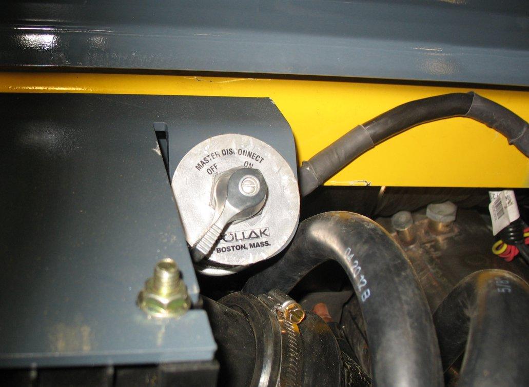
Battery Disconnect Switch
The battery disconnect switch is located in the engine compartment. Turning the switch to the OFF position disconnects the battery from the electrical system.
Caution
Machines equipped with the battery disconnect switch, always turn the switch to the “OFF” position when parking the machine inside an enclosure.
Chapter 4
Indicators And Controls
Warning
Become familiar with all controls before operating the machine. Know how to stop the machine before starting it. The machine is designed and intended to be used only with Manitou-approved attachments or accessories. Manitou cannot be responsible for operator safety if the machine is used with unapproved attachments.
Figure15 – Controls (Hand/Foot Control Option Shown)
A. Accessory Keypad (page36)F. HVAC Vent NozzleK. Right Hand Control (page47)
B. Ignition Keyswitch (page42)G. Cup Holder
C. Information Center Electronic Display (page38)
H. Foot Controls (page47)
D. Control Keypad (page34)I.Throttle Control (page43)
E. Electrical Accessory SocketJ. Left Hand Control (page47)
L. Operator’s Seat (page29)
M.Optional Lights/Lockout Keypad (page37)
Control Keypad
Control Keypad Indicators
Note: Control panel indicators are visible only when the indicator lamps are activated.
Table 2: Control Keypad Indicators
IndicatorDescription
High-Speed Travel Range Indicator Indicates high-speed travel range is activated.
Lift Arm Float IndicatorIndicates lift arm float is activated.
Details
Hydraglide™ Indicator Indicates HydraglideTM lift arm cushion is activated.
Engine Pre-heat Indicator Is lit when ignition keyswitch is in the ON/RUN position and engine pre-heat is required; goes out when engine pre-heat is complete.
Seat Belt Reminder IndicatorIs lit when ignition is turned on as a reminder to lower the operator restraint bar and fasten the seat belt.
Battery Voltage Warning Indicator Indicates battery charging system malfunction. During normal operation this indicator should be OFF.
Engine Air Filter Restriction Indicator Indicates engine air filter requires service. See “Engine Air Cleaner” on page90. During normal operation this indicator should be OFF.
Hydraulic Oil Filter Warning Indicator Indicates hydraulic oil filter requires service. See“Changing Hydraulic Oil Filter” on page93. During normal operation this indicator should be OFF.
Hydraulic Oil Temperature Warning Indicator Indicates hydraulic temperature is too high. During normal operation this indicator should be OFF.
Engine Malfunction Indicator Is lit when the engine electronic control unit (ECU) has detected an error condition. Refer to “Engine Diagnostic Trouble Codes (DTC)” on page108.
Table 2: Control Keypad Indicators
IndicatorDescription
Details
Coolant Temperature Warning Indicator Indicates coolant temperature is too high. During normal operation this indicator should be OFF.
Engine Oil Pressure Warning Indicator Indicates engine oil pressure is too low. During normal operation this indicator should be OFF. IMPORTANT! Immediately shut down the engine if this indicator is lit. Correct the problem before restarting the engine.
Control Keypad Buttons
Button
Description
Parking Brake
Beacon / Position / Work Lights
Self-Leveling Cancel
Power-A-Tach® System Hitch Lock
Power-A-Tach® System Hitch Unlock
Function
Engages / disengages parking brake.
Activates optional beacon, position, and/or work lights. See “Beacon/Position/Work Lights” on page50.
Cancels self-leveling function. LED above button is on when self leveling is off.
Press and hold to lock attachments onto optional Power-A-Tach® System Hitch.
Press and hold to unlock attachments onto the optional Power-A-Tach® System Hitch to allow attachment removal.