22 minute read
CHECKLISTS

Pre-Delivery
The following checklist is an important reminder of valuable information and inspections that MUST be made before delivering the machine to the customer. Check off each item after the prescribed action is taken
Check That:
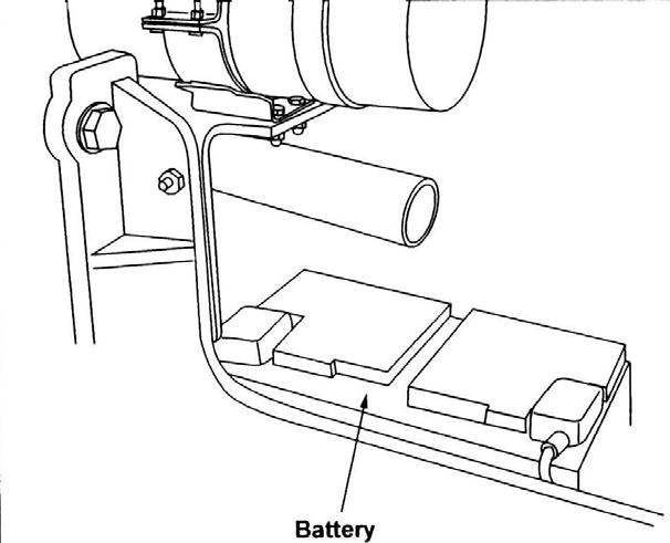
Machine has not been damaged in shipment. Check for such things as dents and loose or missing parts. Correct or replace components as required. Battery is securely mounted and not cracked. Be sure cable connections are tight.
Cylinders, hoses and fittings are not damaged, leaking or loosely connected.
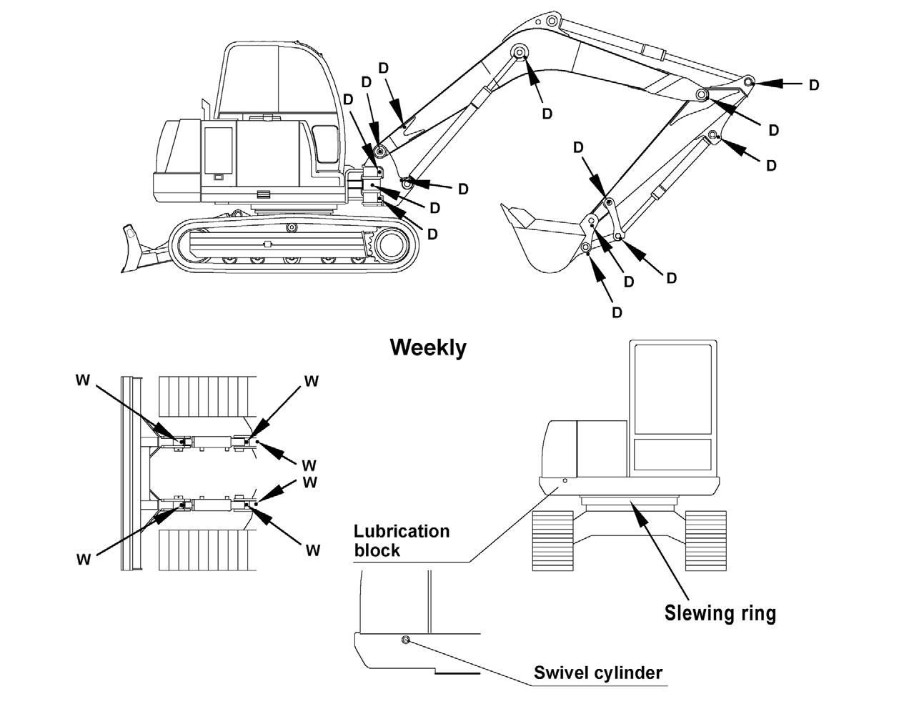
Filters are not damaged, leaking or loosely secured. Machine is properly lubricated and no grease fittings are missing or damaged.
Hydraulic system reservoir, engine crankcase and drive motors are filled to their proper levels. All adjustments are made to comply with settings provided in Chapter 5 Maintenance of this manual. All guards, shields and decals are in place and secured.
Model and serial numbers for the machine are recorded in the space provided on this page and on page1.
IMPORTANT: Start the engine and test run the unit while checking that all controls operate properly.
Check That:
Drive controls and boom/arm/bucket/dozer blade/ swing/pivot controls operate properly and are not damaged or binding.
Drive controls are properly adjusted for correct neutral position.
The parking and travelling gear brake, along with the lock-out devices, are activated with the machine stationary (no pilot control pressure).
All hydraulic functions are NOT operational with the left control console in the raised lock-out position.
I acknowledge that pre-delivery procedures were performed on this unit as outlined on this page.
Dealership’s Name
Dealer Representative’s Name
Date Checklist Filled Out
Model & Serial Number
Delivery
The following Checklist is an important reminder of valuable information that MUST be passed on to the customer at the time the unit is delivered. Check off each item as you explain it to the customer.
Check That:
Review with the customer the contents of this manual; especially:
The Safety and Operation chapters of this manual, regarding the safe operation of the machine.
The Maintenance and Troubleshooting chapters for information regarding the proper maintenance of the machine. Explain that regular lubrication and maintenance is required for continued safe operation and long machine life.
Give this Operator’s Manual to the customer and instruct the customer to read and completely understand the contents before operating the machine.
Completely fill out the Owner’s Registration, including customer’s signature and return it to the Gehl Company.
Explain that a copy of the product warranty is included on the inside front cover of this operator’s manual.
Customer’s Signature
Date Delivered
Operating Controls Warning
•Read and understand this entire manual. Follow warnings and instructions for operation and maintenance. Failure to follow instructions can result in injury or death.
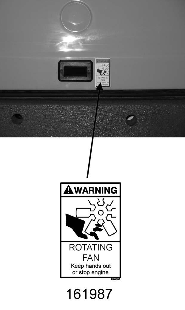
•Read and understand all safety decals before operating the machine. DO NOT operate the machine unless all factory-installed guards and shields are in place.
•Be sure you are familiar with all safety devices and controls before operating the machine.
•Know how to stop the machine before starting.
•Use only with approved accessories or referral attachments. The manufacturer cannot be responsible for safety if the unit is used with nonapproved attachments.
•Check for correct function after adjustments or maintenance.
Machine Orientation Guards and Shields
Whenever possible, guards and shields are used to protect potentially hazardous areas on the machine. In many places, decals are also provided to warn of potential hazards and/or to display special operating procedures. See “Safety Decals” on page18.
The left operator’s console should be raised to enter and exit the cab. In the raised position, the console locks out all hydraulic functions of the machine. See Figure 4-1.
Cab Equipment and Controls (SN AB01967 and before & SN CAB 44829 and before)
1.Auxiliaryhydraulicfootpedal control
19.Fusepanel
2.Leftdriveleverwithfootpedal11.Throttlelever20.Heater
3.Seatspringtensionadjustment12.Rightcontrolleverforboomand bucketcylinders,horn
4.Rightdriveleverwithfootpedal13.Instrumentpanel22.Latchhandletoopenhydraulic valvecover
5.Seatbackadjustment14.Radio23.Latchhandletoopenengine cover
6.Footrest15.Speaker24.WarningArm/Levertofoldback leftsteeringcontrolconsole
7.Dozerbladeleverwithfootpedal16.IgnitionKeySwitch25.Seatadjustment
8.Heatingandairvents17.Armrest
9.Cablight18.Storage
Excavator Components

Ref. No. Description
1 Not assigned
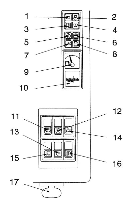
2 Hydraulic oil filter indicator (red) – Hydraulic oil filter indicator light comes on when the hydraulic oil filter requires servicing.
3 Air filter indicator (red) – Air filter indicator light comes on when the air filter requires servicing.
4 Battery charge indicator (red) – Battery charge indicator light comes on when the ignition is turned on and goes off as soon as the engine is running. The alternator or the charging circuit is faulty if the indicator light comes on with the engine running. The battery is no longer charged.
5 Coolant temperature indicator (red) – Coolant temperature indicator light comes on if the coolant temperature rises above specification.
6 Engine oil temperature indicator (red) – Engine oil temperature indicator light comes on if the engine oil temperature rises above specification.
7 Glow plug indicator (yellow) – Glow plug indicator light comes on when the ignition key is in the glow plug activation position. Indicator will go out when the glow plugs have heated sufficiently to start the engine.
8 Fuel level gauge – The fuel level gauge shows the amount of fuel in the tank.
9 Overload indicator – Overload indicator light comes on when the load is too heavy for the excavator.
10 Not assigned
11 Hourmeter – Indicates the total operating hours of the machine. Use the hourmeter to track maintenance in the maintenance log.
12 Windshield wiper switch (cab models only) – Pressing the two-position switch to the first position turns on the windshield wiper. Pressing and holding the switch indicator in the second position activates the washer fluid pump.
13 Ventilation fan (two-speed) – Press the two position switch to turn on the ventilation fan. Pressing switch to the first position is the low fan speed position, and the second position is the high fan speed position. If the heater control (cab model only) is in the heating position, this switch will function as the cab heater ON/OFF switch.
14 High-speed switch (transport speed) – Press the switch to enable high travel speed.
15 Work light switch – Press the switch to the ON position to turn on the boom work light.
16 Chassis headlights – Press the switch to the ON position to turn on the chassis headlights.
17 Central lubrication system – Press the switch to turn the central lubrication system ON/OFF.
18 Not assigned
19 Not assigned
20 Not assigned
21 Roof lights (option) – Press the switch to the ON position to turn on the roof lights.
22 Pumping delivery reduction – If the switch is off, the pump delivers 30.9 gpm (117 l/min). If the switch is on, the pump delivers 25 gpm (95 l/min).
23 Not assigned
24 Potentiometer – Turn the dial to adjust the hydraulic pump flow by changing the pressure.
25 Air conditioning – Turn the dial to turn the air conditioning ON/OFF.
26 Thermostat – Turn the dial to control the cold/hot temperature of the air entering the cab.
27 Fan – Turn the dial to control the intensity of the air blowing into the cab. Select one of the three settings.
Instrument Panel, Switches and Indicators (SN AB01967 and before)
1.BatteryVoltageIndi cator10.HourMeter
2.EngineOilPressureIndicator11.WindshieldWiperSwitch
3.CoolantTemperatureIndicator12.HeaterControlSwitch
4.GlowPlugIndicator13.RearWorkLightSwitch(optional)
5.EngineAirFilterIndicator14.TravelSpeedSelectorSwitch
6.HydraulicOilFilterIndicator15.BoomWorkLightSwitch
7.WorkLightIndicator16.CabWorkLightSwitch
8.LowFuelIndicator17.IgnitionKeyswitch
9.FuelLevelGauge
1. Battery Voltage Indicator
Indicator light comes on when battery voltage is too low.
2.Engine Oil Pressure Indicator
During normal operation, this indicator light should remain off. The indicator will light if the engine oil pressure drops too low. If this occurs, shut off the engine IMMEDIATELY and determine the cause of the pressure drop.
3.Coolant Temperature Indicator
Indicator light comes on when coolant temperature is too high.
4.Glow Plug Indicator
Indicator light comes on when the ignition key is turned on. Indicator will go out when glow plugs have heated sufficiently to start the engine.
5.Engine Air Filter Indicator
Indicator light comes on when engine air filter is too dirty.
6.Hydraulic Fluid Filter Indicator
Indicator light comes on when hydraulic oil filter is too dirty.
7.Work Light Indicator
Indicator light comes on when work lights are turned on.
8.Low Fuel Indicator
Indicator light comes on when fuel level is low.
9.Fuel Level Gauge
The fuel level gauge shows the amount of fuel in the tank.
10.Hour Meter
Indicates total operating hours of the machine. Use the hour meter to log maintenance in the log located in Chapter 4 – Maintenance.
11.Windshield Wiper Switch
Pushing the switch to the first position turns the windshield wiper on. Pushing and holding the switch in the second position activates the washer fluid pump.
12.Heater Control Switch
Turns on the cab heater and controls the fan speed.
13.Rear Work Light Switch (Optional)
Turns the optional rear work light on and off.
14.Travel Speed Selector Switch
Turn the switch on to engage high travel speed. With switch on, machine can only move straight forward or backward. It will not steer to either side.
15.Boom Work Light Switch
Turns the boom work light on and off.
16.Cab Work Light Switch
Turns the work light on the front of the cab on and off. The switch has two positions:
First position – low beam
Second position – high beam.
17.Ignition Key Switch
With the key in the OFF (vertical) position, all power is shut off. This is the only position that the key can be inserted or removed from the switch.
With the key turned one position clockwise (RUN) from the vertical position, power is turned on to all controls and electrical circuits. In cold weather the glow plug indicator will come on while the glow plugs warm intake air.
With the key turned fully clockwise (START) and held in position, the the engine will start. Release the key after the engine starts.
Note: The key must always be returned to the OFF position between attempts to start the engine in order to activate the glow plug system.
Pump Output Regulator (not shown)
Rotating control adjusts maximum flow of hydraulic oil from the pump.
Economy Mode (not shown)
Move switch to the Economy Mode to reduce engine power to save fuel.
Ignition Key Switch (SN AB01968 and before)
NOTE: The engine can only be started if the left control lever console is pivoted down into the operation position.
With the key in the fully counter-clockwise “P” position, all power is shut off. The key can be inserted or removed when the switch is in this position.
With the key in the “0” position, power to the accessory circuit is turned on. The key can be inserted or removed when the switch is in this position.
With the key in the “I” position, power is turned on to all controls and electrical circuits. The battery charge indicator light and the oil pressure indicator light will come on.
With the key in the “II” position, the glow plug indicator will come on while the glow plugs warm the engine cylinders in cold weather.
With the key turned fully clockwise “III” and held in position, the engine will start and the indicator lights should go out. Release the key after the engine starts (the key returns to the “I” position when it is released after starting the engine).
NOTE: The key must always be returned to the “I” position between attempts to start the engine in order to activate the glow plug system.
Travel Controls
Warning
Leversandcontrolsshouldreturntoneutral positionwhenreleased.
Besuretheleversandcontrolsareinthe neutral(middle)positionbeforestartingthe engine.
Operatecontrolsgraduallyandsmoothly. Excessivespeedandquickcontrolmovements withoutregardforconditionsandcircumstancesarehazardousandcouldcausean accident.
Warning
Besurethatthedozerbladeis“infront.”When theoperator’scabisfacingforward,theblade willbevisibleandthetravelcontrolswilloperateasexpected.Ifthedozerbladeisnotvisible,theoperator’scabisfacingtotherear,and thetravelcontrolswilloperateinreverse.
Forward Travel
Push both travel control levers or pedals forward. The farther these are moved, the faster the machine will travel forward. See Figure 4-8.
Reverse Travel
Pull both travel control levers or pedals back. The farther these are moved, the faster the machine will travel in reverse. See Figure 4-8.
Turning During Travel
To turn left while moving forward, move the right control lever farther forward; to turn right while moving forward, move the left control lever farther forward. See Figure 4-9.
Figure 4-8 Travel and Auxiliary Control Levers

Figure 4-9 Travel Controls
Spin Turn
Move the levers in opposite directions to spin the machine on its axis. To spin turn left, move the right control lever forward while pulling the left control lever rearward; to spin turn right, move the left control lever forward while pulling the right control lever rearward. See Figure 4-9.
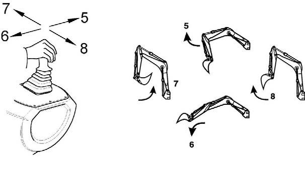
SAE Operating Controls
SAE boom and bucket functions are controlled by the right and left joystick control levers located on the seat consoles.
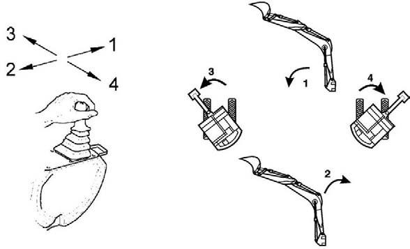
SAE Left Joystick – See Figure 4-10.
1 – Arm extend
2 – Arm retract
3 – Swing left
4 – Swing right
ISO Operating Controls
ISO boom and bucket functions are controlled by the right and left joystick control levers located on the seat consoles.
ISO Left Joystick – See Figure 4-12.
1 – Boom lower
2 – Boom raise
3 – Swing left
4 – Swing right
SAE Right Joystick – See Figure 4-11.
5 – Boom lower
6 – Boom raise
7 – Curl bucket in
8 – Curl bucket out
ISO Right Joystick – See Figure 4-13.

5 – Arm extend
6 – Arm retract
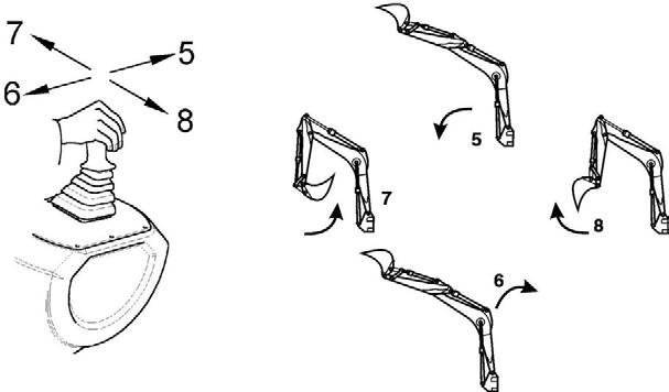
7 – Curl bucket in
8 – Curl bucket out
NOTE: The farther the controls are moved from center, the faster the machine will function.
NOTE: The farther the controls are moved from center, the faster the machine will function.
The boom can be slewed, or swung, without moving the swing frame by pressing and holding the slewing the boom button on the bottom of the left hand joystick, and then pressing the auxiliary hydraulics pedal forward or rearward. See Figure 4-14. Pressing the auxiliary hydraulics pedal forward slews the boom to the left. Pressing the auxiliary hydraulics pedal rearward slews the boom to the right.
Additional machine functions are controlled by the buttons located on top of the joysticks. See Figure 4-15.

NOTE: If auxiliary hydraulics are used with swivel buckets, there may be jerking motions of the boom or the dipper arm.
Left Joystick: Top Buttons
•Left Button - steer auxiliary hydraulics left.
•Right Button - steer auxiliary hydraulics right.
Left Joystick: Bottom Button
•To slew the boom to the right or left, first press and hold this button. Then press the pedal forward to slew the boom to the right and rearward to slew the boom to the left.
Right Joystick: Top Buttons
•Left Button decreases engine RPM to match manual throttle setting.
•Right Button increases engine RPM above manual throttle setting.
Right Joystick: Bottom Button
•Horn.
The dozer is controlled by the dozer lever. See Figure 4-16.
•Push control forward to lower the blade.
•Pull control rearward to raise the blade.
Operator’s Seat Adjustments
NOTE: The operator’s seat left console must be raised in order to exit the cab. In the lowered or work position, all operational functions are activated, and operator exit is blocked by the left console. In the raised position, all hydraulic functions of the machine are locked out. Only adjust the seat when the excavator is stopped.

1. Seat Suspension Adjustment
Turn the lever (1) to adjust the seat suspension for the operator’s weight. An indicator on the front of the seat base shows the weight adjustment. See Figure 4-17.
2.Seat/Console Adjustment
The seat/console lever (2) allows the operator to move the entire seat and console assemblies forward or rearward. See Figure 4-17.
3.Seat Adjustment
The seat adjustment lever (3) allows the operator to move the seat only (without consoles) forward or rearward. See Figure 4-17.
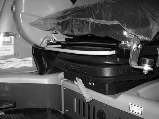
SAE/ISO Operating Controls Selector Valve
Located on the bottom, left side of the chassis is the SAE/ISO Selector Valve. The machine has been set at the factory for SAE standard operation.
Changing from SAE to ISO:
1.To access the SAE/ISO operating controls selector valve (1), rotate the cab to an angle of slightly less than 90°, as shown. See Figure 418.
2.Follow “Mandatory Safety Shutdown Procedure” on page11.
3.Crawl underneath the chassis between the tracks. See Figure 4-18.
4.Loosen the wing nut (2) and rotate the selector valve (3) to position. See Figure 4-19.
5.Retighten the wing nut (2). See Figure 4-19.
Ventilation
Windshield
Warning
Whenopeningthewindshield,besuretolock bothlatches.Whenclosingthewindshield, keephandsonthehandleandawayfromthe pathofthewindow.
Opening the Windshield
1.The windshield can be opened for ventilation. Turn the latches (1) located at the upper corners of the windshield.
2.Grasp the handle (2) and pull the windshield up until latches lock in the open position. See Figure 4-20.

Closing the Windshield
1.Lower your head to avoid getting hit by the windshield.
2.To close the windshield, turn the latches (1). Grasp the handle (2) and push the windshield until the latches lock in the closed position. See Figure 4-20.
Side Window
The side window can be opened for ventilation. Squeeze the latch (2) located on the window, slide the window to the desired position, and release the latch. See Figure 4-21.
Vents
There are two side vents (1) located below the side window. Open the slats for better ventilation. See Figure 4-21.
Cab Door Latch
When fully opened, the left cab door will latch in position to the side of the cab. To release the latch, use the knob located on the inside of the door frame.


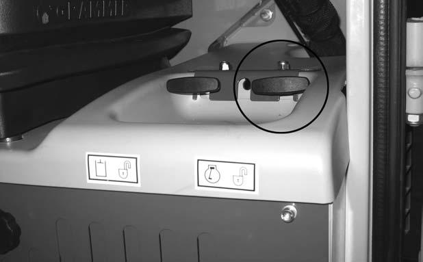
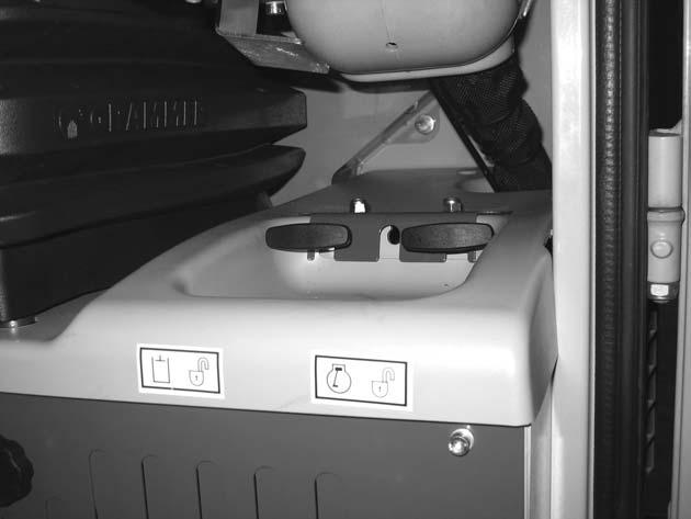
Remote Engine and Hydraulic Valve Cover Latches
The engine cover (2) and hydraulic valve cover (1) latches are located near the operator’s seat, on the left side.
Machine Operation Warning
•Read and understand this entire manual. Follow warnings and instructions for operation and maintenance. Failure to follow instructions can result in injury or death.
•Read and understand all safety decals before operating the machine. DO NOT operate the machine unless all factory installed guards and shields are in place.
•Be sure you are familiar with all safety devices and controls before operating the machine.
•Know how to stop the machine before starting.
To unlatch a cover, pull the respective latch handle. The cover can then be opened.
•Use only with GEHL Company approved accessories or referral attachments. The GEHL Company cannot be responsible for safety if the unit is used with non-approved attachments.
•Check for correct function after adjustments or maintenance.
Pre-operation Checklist
IMPORTANT: See “Recommended Lubricants” on page59. Only use the specified lubricants for the proper engine and hydraulic oil specifications.
Check the following items at the beginning of each work day or every 12 working hours:
•Seat belt and mounting hardware
•Safety decals (replace as required)
•Air cleaner and intake hoses
•Engine coolant level and system for leaks
•Clean engine area of any flammable materials (clean as required)
•Engine oil level (fill if required)
•Hydraulic system for leaks
•Hydraulic fluid level (fill if required)
•Pivot points for proper operation
•Track tension
•Broken and/or loose parts (repair as required)
•Fuel level
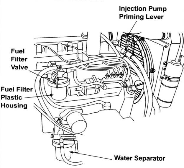
IMPORTANT: Do not completely drain the fuel tank while running the excavator. When this happens, air enters the fuel system, and the fuel system must be bled. Always completely fill the tank with fuel at the end of each working day.
Warning
Neveruseetherstartingaids.Glowplugsare usedforcoldstarting.Theglowplugcancause etherorotherstartingfluidstodetonate,causinginjury.
Engine Start and Stop
NOTE: When all machine controls are stationary (no pilot control pressure), the swing motor and travel motor brakes are automatically applied. When any control is activated, the appropriate brake is automatically released.
NOTE: All hydraulic functions are locked out when the operator’s seat left console is in the raised position.
Engine Start Procedure DANGER
DONOTruntheengineinanenclosedarea withoutproperventilation.Besurethereisadequatefreshairifrunningthemachineinan enclosedarea.
1.Adjust the operator’s seat to desired settings.
2.Fasten the seat belt.
3.Be sure all levers and controls are in the neutral positions.
4.Insert ignition key into switch and turn right (clockwise) to the (II) position. Indicators for oil pressure and battery voltage will light. In cold weather the glow plug indicator will light while the glow plugs warm the engine cylinders.
5.Turn the key fully clockwise and hold until the engine starts, then release the key.
NOTE: The key must be returned to the (I) position between attempts to start the engine in order to activate the glow plug system.
IMPORTANT: Do not activate the starter motor for longer than 20 seconds during each starting attempt. If the engine does not start, turn the key fully counter-clockwise, wait 30 seconds, and then attempt to start the engine again.
IMPORTANT: Indicator lights must go out when the engine starts. If they do not, turn the engine off IMMEDIATELY. Do not use the machine until the problem has been identified and repaired.
6.Allow the engine to run at idle speed for approximately 10 - 15 minutes to fully warm up all systems.
Cold Weather Engine Starting Procedure
NOTE: Install an in-block or tank-style engine heater, which will keep engine block and oil warm for easier cold-weather starting.
NOTE: Be sure the engine oil is correct type and viscosity for the ambient (air) temperature. See “Recommended Lubricants” on page59.
NOTE: Be sure the battery is fully charged.
1.Start the engine. See “Engine Start Procedure” on page45.
2.Advance the throttle to 1/4 engine speed for a faster warm up.
3.As the engine warms up, move the throttle lever to the idle position.
Engine Shutdown
Mandatory Safety Shutdown Procedure
Before leaving the machine:
1.Lower the working equipment to the ground.
2.Run the engine at idle speed for a few minutes to allow systems to cool after operation at full speed.
IMPORTANT: If the engine is shut down without a cooling period, damage can occur.
3.Turn the key fully counter-clockwise to shut off the engine.
4.Lock out the controls by raising the left control console.
5.Remove the ignition key and take it with you.
New Machine Break-in Procedure
A new machine requires reduced operational speed during the first 100 operating hours for proper break-in. If the machine is subjected to hard use during the break-in period, damage can occur.
Perform the following when operating a new machine:
•Check all fluid levels:
•Engine oil
•Engine coolant
•Hydraulic fluid
•Start the engine and let it idle for 10 - 15 minutes to fully warm-up all systems.
•Operate the machine at about 80% of maximum loads and speed.
•At the end of the first 100 operational hours, drain and replace the engine oil and engine oil filter.
Travel WARNING
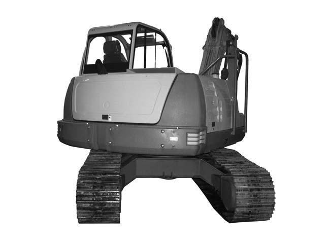
•Before operating the travel levers, make sure that you know which direction the machine is pointing. If the dozer blade is not visible from the operator’s cab, you are facing the rear of the machine and the travel controls will act the reverse of normal operation.
•Before moving, make sure that there are no personnel in the way of the machine. Sound the horn to alert workers that you are about to move the machine.
•Be sure the path is clear during travel.
•Use extreme caution when reversing travel. Be sure there is a clear path behind the machine.
•Operate the travel control levers smoothly to avoid sudden starts or stops.
•Before leaving the operator’s seat, be sure to lock out all control systems and shut down the engine to avoid accidental activation.
Travel Speed Selection
Two travel speed ranges can be selected by using the travel speed switch located on the control console. See “Instrument Panel, Switches and Indicators (SN AB01968 and up),” Reference 14, page33.
Travel speeds are:
•Slow Speed Maximum = 2.1 mph (3.4 km/h)
•High Speed Maximum = 3.6 mph (5.8 km/h)
General Travel Instructions
1.Avoid sudden movements and sharp turns.
2.Travel slowly on rough, frozen, or uneven terrain.
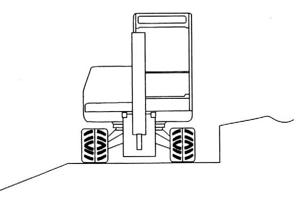
3.Travel straight up and down slopes, never travel across the slope. See Figure 4-23. Extend the arm and lower the boom to keep the bucket about 12” (305 mm) off the ground. If the machine starts to slide or becomes unstable, lower the bucket to regain control. If the engine stalls, lower the bucket, be sure that all controls are in neutral and restart the engine. See “Operating on Slopes” on page48.
Figure 4-24 Track Cleaning
NOTE: When using the boom and arm to lift any portion of the machine, roll the bucket until the round base is against the ground. The angle of the arm to the boom should be at 90º. See Figure 4-24.

4.If dirt or mud builds up in the track frame, raise the track frame using the boom and arm and then rotate the elevated track to clean it. Be sure that the build-up has been cleared from the track. Repeat for other track. See Figure 424
5.To travel straight, forward or rearward, push both travel control levers (or pedals) forward or rearward. The farther the levers (or pedals) are pushed, the faster the travel speed.
6.Pivot (or wide) turns are made by rotating only one track forward or rearward. The machine will pivot on the stationary track.
7.Spin turns are made by rotating one track forward and one track rearward. The machine will spin around its mid-point.
8.The excavator can travel in water that comes up to the top of the upper track rollers.
IMPORTANT: Be sure that the footing is solid so that the machine will not sink.
Operating Instructions
Joystick Controls
Extending and retracting the cylinders (boom, arm and bucket) are controlled by the joysticks located on the consoles attached to the operator’s seat. See “SAE Operating Controls” and “ISO Operating Controls” on page40 for control configurations.
NOTE: The farther the controls are moved, the faster the machine will function.
NOTE: Travel and swing brakes are automatically applied. Springs set the brakes when the swing or travel controls are in their neutral position, or when the engine is off. The brakes are hydraulically released when hydraulic pressure is applied during swing or travel functions.
Operating Precautions
Danger
•DO NOT push down with the dozer blade to elevate the front end of the tracks. This will cause the machine to become unstable.
•DO NOT excavate underneath the machine.
•Always be sure that there is adequate support when working near trenches or drop-offs. Be aware of conditions that could cause the trench/drop-off wall to collapse, resulting in risk of injury or death.
•Be sure that there is the proper clearance from overhead electrical lines.
•Be sure that all underground electrical power and gas supply lines are clearly marked and avoided.
Warning
•DO NOT rest your feet on the travel pedals during normal machine operation. Unexpected machine movement may occur in this situation.
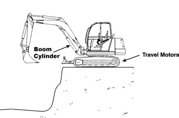
•When working close to the excavated edge, be sure that the ground the machine is sitting on is solid. Keep the heavy travel motors to the rear. See Figure 4-25.
DO NOT use machine travel or swing to provide additional breakout force when the bucket is in the ground.
DO NOT jam the bucket into the ground and use the weight of the machine to provide additional breakout force.
DO NOT use the bucket as a hammer or ramming device.
When working on soft or muddy ground, be sure that the machine is not sinking.
IMPORTANT: When digging at the maximum excavation depth, BE SURE that the dozer blade does not contact the boom cylinder. See Figure 4-25. Damage to the boom cylinder may occur if the dozer blade contacts the boom cylinder.
Operating on Slopes
Warning
•Do not travel up or across a slope steeper than 15°. Do not travel down a slope steeper than 25°. Keep boom centered while traveling.
•Keep attachments as low as possible when traveling on slopes or rough terrain.
Figure 4-27 Travel Down Slope
Operating on a slope is hazardous. It is recommended that the work area be leveled as shown in Figure 4-26. If this is not possible, use the following guidelines.
•Travel straight up and down slopes; never travel across the slope. See Figure 4-27. Extend arm and lower boom to keep the bucket about 12” (305 mm) off the ground. If the machine starts to slide or becomes unstable, lower the bucket to regain control. If the engine stalls, lower the bucket, be sure that all controls are in the neutral position and restart the engine.

•When traveling down a slope, control the speed with the travel levers and throttle controls.
•When going down grades that exceed 15°, put the machine in the position shown in Figure 4-27. Reduce engine RPM.
•To achieve the best stability while excavating, lower the dozer blade to the ground.
•Operate as slowly as possible and avoid sudden changes in direction.
•Avoid traveling over objects such as rocks, trees, stumps, etc.
•Stop the excavator travel before moving the bucket or dozer controls.
•Slow down the work cycle. Take your time.
•Avoid working with the tracks positioned across the slope. Position the excavator with the blade facing downhill and lowered.
•Avoid swinging or extending the bucket farther than necessary in a downhill direction. If you must swing the bucket downhill, keep the boom low and skid the bucket along the ground.
•When working with the bucket on the uphill side, keep the bucket as close to the ground as possible. Unload far enough away from the excavation to prevent the possibility of a cave-in.
Operating in Cold Weather
In cold weather, mud should be removed from the machine before parking. If possible, park the machine on solid ground, or wood planks, to prevent the track or undercarriage from freezing to the ground.
Operating in Water
Do not operate or immerse the machine in water higher than the top of the upper track rollers.
Thoroughly grease the machine if it has been operated in deep water.
Slewing the Boom WARNING
Workingwiththeboomslewedtotheside reducesliftingcapacity.
Overloadingthebucketcancauseanunstable conditionandincreasethepossibilityoftippingthemachine.
The excavator boom can be slewed 50º to the right and 80º to the left from the basic front position. This allows excavation of trenches along walls, fences, etc. See Figure 4-28.
1.Press and hold the auxiliary control button, located on top of the left joystick.
2.Press the auxiliary hydraulics pedal with your toe or heel. Pressing the front of the auxiliary hydraulics pedal slews the boom to the left and pressing the back of the auxiliary hydraulics pedal slews the boom to the right. See Figure 4-29.

NOTE: Bucket controls do not change when slewing the boom.
Grading
Bulldozing WARNING
•Be sure there is proper clearance for the front end attachments when bulldozing.
•Be sure that the front end attachments do not contact overhead power lines or obstructions during bulldozing.
•DO NOT drive the machine into the excavation or onto loose soil, which can cause an unstable condition, and could possibly tip the machine.
1.Raise or lower the dozer blade using the control lever located next to the right joystick. Move the lever forward to lower the dozer blade and rearward to raise the dozer blade. See Figure 4-30.
2.The boom must be fully raised and the bucket curled in (up) when grading.
3.When grading, the material may be pushed away to the front or side.
4.Raise the dozer blade slightly if excessive resistance occurs.
5.When the blade is in position, use the travel controls to move the machine as in normal travel.
Transporting
Towing
The excavator can be towed by using the towing bracket (1). Secure a towing shackle, shackle pin and lock (2) of adequate size to the towing bracket (1) as shown. See Figure 4-31. Tow the machine slowly.

Lifting the Machine WARNING
•Use a lifting device with sufficient capacity for the weight of the machine plus any attachments.
•Maintain center-of-gravity and balance points on the machine. See Figure 4-32.
•Do not swing the boom.
•Never lift the machine with the operator aboard.
Secure the lifting fixture sling to the lifting points (1) on the machine as follows. See Figure 4-32.
•Length L1 on the lifting sling for the boom must be 11’5” (3.5 m) long.
•Length L2 (two locations) on the lifting sling must be 13’1” (4.0 m) long.
See Figure 4-32. Do not exceed the rated load capacity of the lift. See “General Specifications” on page4 for excavator weight.
Figure 4-32 Machine Lifting Points
Loading and Transporting
Refer to Figure 4-33. Use only transporters that are in proper working order and are approved for use on public roads.
When using ramps:
•Do not exceed an incline of 17° (30%).
•Clean dirt, mud, ice and snow from the ramps and tracks.
•Use metal loading ramps with a slip-resistant surface, and with beveled ends to prevent damage to rubber tracks.
Loading Procedure:
1.Attach ramps securely to the transporter to prevent them from slipping off during loading.
2.Load the transporter on solid, even ground.
3.Engage the transporter parking brake and chock the wheels.
4.Determine the direction of the track movement (blade facing forward) before moving the excavator onto the ramps.
5.After the excavator is on the transporter, lower the dozer blade onto the loading surface.
6.Rotate the cab 180° so that the excavator is facing rearward. See Figure 4-33.
7.Lower the bucket onto the loading surface and turn off the excavator engine.

8.Lock the cab.
9.Place chocks under the excavator tracks.
10.Secure the excavator to the transporter at the tie-down points (1) to prevent the excavator from slipping, overturning or moving during transport. See Figure 4-33.
NOTE: The tie-down points (1) on the excavator are identified by decals. See Figure 4-33.