5 minute read
MAINTENANCE1202

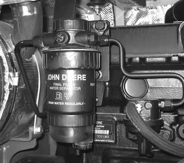
Fuel Filter/Water Separator: Tier 2 Engine John Deere 4045TF270 (SN AC02633 and up)
The fuel filter/water separator is located at the rear of the engine as shown (1). See Figure 5-13.

5.The fuel system must be purged of air after changing the fuel filter, or if the fuel tank has been run dry.
6.If water is seen in the plastic bowl, the bowl will need to be drained. If necessary, open the valve (4) to drain the plastic bowl. See Figure 5-14.
7.Clean the new fuel filter element bottom.
8.Put oil on the base of the plastic bowl.
9.Install the plastic bowl.
10.Discard fuel/water according to local regulations. DO NOT pour fluids onto the ground or down a drain.
11.Close the valve opened in step 6.
Fuel Filter/Water Separator: Tier 1 Engine Yanmar 4TNE106T-NS (SN AB00473-AB03158)
Fuel Filter
1.Unscrew the plastic ring (2) to change the fuel filter and clean dirt from the housing. See Figure 5-14.
2.Clean around the filter housing. Put fuel on the seal of the new fuel filter.
3.Install the new fuel filter and hand tighten.
4.Remove the plastic bowl (3). See Figure 5-14.
Unscrew the clear plastic housing (Figure 5-15) to change the filter element and clean dirt from the housing. Clean around the filter housing. Put oil on the seal of the new filter element. Install the fuel filter and hand tighten.
The fuel system must be purged of air after changing the fuel filter, or if the fuel tank has been run dry.
Water Separator
If water is seen in the plastic water separator bowl, the bowl will need to be drained.
1.Shut off fuel using water separator fuel valve.
2.Unscrew and remove plastic water separator bowl.
3.Discard fuel/water according to local regulations. DO NOT pour fluids onto the ground or down a drain.
4.Reinstall filter bowl.
5.Open fuel valve.
6.Purge air from the fuel system.
Purging Air from the Fuel System: Tier 2 Engine John Deere 4045TF270 (SN

AC02633 and up)
Warning
DONOTbleedaironahotengine.Spilledfuel cancauseafire.
If the fuel tank is run dry, or if the fuel filter, water separator or fuel lines are replaced, trapped air must be removed, or bled, from the fuel system. Bleed air from the fuel system according to the following steps:
1.Check the fuel filter/water separator for water or dirt, empty it if necessary.
2.Drain and discard water according to local regulations.
Lever
3.Loosen the drain plug (2) at the bottom of the fuel filter/water separator by turning it two or three times. See Figure 5-16.
4.Loosen the vent plug (1) on the fuel filter base by turning it twice. See Figure 5-16.
5.Drain the water from the bottom until fuel starts to run out. As soon as fuel starts to run out, close the drain plug (2) tightly. See Figure 5-16.
6.Actuate the fuel pump backing pump lever (3) until there are no more air bubbles in the fuel. See Figure 5-16.
IMPORTANT: There should be resistance while performing step 6. If there is no resistance, activate the starter for a few seconds. Do NOT run the engine.
7.Retighten the vent plug (1) and keep operating the fuel pump backing pump lever (3) until the pumping effect is no longer felt. See Figure 516.
8.Press the fuel pump backing pump lever (3) toward the engine as far as possible. See Figure 5-16.
Purging Air from the Fuel System: Tier 1 Engine Yanmar 4TNE106T-NS
(SN AB00473-AB03158)
If the fuel tank has been run dry, or the fuel filter or fuel lines have been replaced, trapped air will have to be removed, or bled, from the fuel system.
1.Turn the fuel filter valve (Figure 5-17) to the open position (vertical).
2.While operating the priming lever on the fuel injector pump, loosen the air bleeding screw (A, Figure 5-17) on the fuel filter. When fuel starts flowing from the bleeder valve (A) without any air or bubbles, tighten the bleeder screw (A).
3.Repeat step 2 for bleeder screws B, C, D and E (Figure 5-17).
Coolant System
Checking Coolant Level (SN AC02633 and up)
Warning
•Engine must be cold.
•Be careful to avoid burns when removing the cap.
•Keep face away from cap.
•Cover cap with a cloth, turn cap slowly to release pressure.
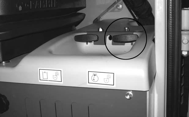
1.Lift the hydraulic tank cover to access the expansion reservoir. See Figure 5-18.

Checking Coolant Level (SN AB00473-AB03158)
Warning
•Engine must be cold.
•Be careful to avoid burns when removing the cap.
•Keep face away from cap.
•Cover cap with a cloth, turn cap slowly to release pressure.
1.Pull the engine cover latch handle (located on the left side of the operator’s seat) and raise the engine cover.
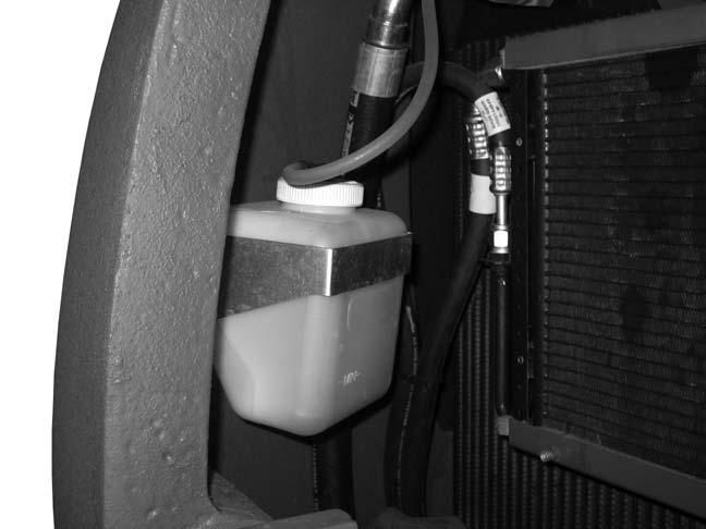
2.Check the coolant level in the expansion reservoir. See Figure 5-19.
3.If low, slowly loosen cap and allow pressure to escape.
4.Completely remove cap and fill reservoir to MAX line. See “Fluid Capacities/Lubricants: John Deere 4045TF270 (SN AC02633 and up)” on page5.
5.Check the radiator coolant level.
Refer to the engine manual for correct coolant mixture for the engine.
2.Check the coolant level in the expansion reservoir (Figure 5-20).
3.If low, slowly loosen cap and allow pressure to escape.
4.Completely remove cap and fill reservoir to FULL line.
Refer to the engine manual for correct coolant mixture for the engine.
Figure 5-20 Coolant Level Check ELECTRICAL SYSTEM

Fuses (SN AC02633 and up)
The fuse panel is located on the right console. See Figure 5-21.


To replace a fuse, remove the panel cover and pull the old fuse from the socket. Install a new fuse of the same rating and re-install the fuse panel cover.
IMPORTANT: Determine what caused the fuse to blow and repair the problem before replacing the fuse.
Refer to “Fuse Panel” on page38 in Chapter 4 for fuse identification.
To access the master fuse panel and relay, remove the panel cover located underneath the right side console as shown.

Fuses (SN AB00473-AB03158)
The fuse panel is located on the right-hand console (Figure 5-24).

To replace a fuse, remove the panel cover and pull the old fuse from the socket. Install a new fuse of the same rating and re-install the fuse panel cover.
NOTE: Determine what caused the fuse to blow and repair the defect.
Refer to page35 in Chapter 4 for fuse identification.
Battery cables must be clean and tight. Remove any acid or corrosion from the battery and cables using a sodium bicarbonate and water solution. Cover the battery terminals and cable ends with battery-saver grease.
NOTE: The battery is maintenance-free and requires no other service.
Battery: Old Location
Battery: New Location
Warning
Batteriescontainacidwhichburnseyesand skinoncontact.Wearsafetygogglesand protectiveclothingtokeepacidoffbody.
Incaseofacidcontact,washimmediatelywith waterforseveralminutes.Incaseofeyecontact,getmedicalattentionimmediately.
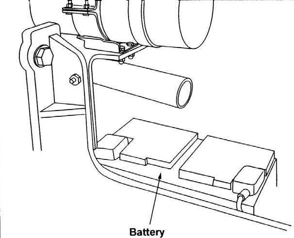
The battery is located under the hydraulic tank cover. See Figure 5-25. To access the battery, use the key to open the hydraulic tank cover.
Warning
Batteries contain acid which burns eyes and skin on contact. Wear safety goggles and pro-tective clothing to keep acid off body.
In case of acid contact, wash immediately with water for several minutes. In case of eye contact, get medical attention immediately.
The battery is located under the engine cover, near the right rear counterweight. See Figure 4-4 on page31, Excavator Components, item #9.

To access the battery, pull the engine cover latch handle (located on the left side of the operator’s seat) and open the engine cover.
The battery cables must be clean and tight. Remove any acid or corrosion from the battery and cables using a sodium bicarbonate and water solution. Cover the battery terminals and cable ends with battery saver grease.
The battery is maintenance-free and requires no other service.