6 minute read
OPTIONAL FEATURES & ACCESSORIES

NOTE: Installation information for all of the Optional Features & Accessories, described in this chapter, is provided in the Set-up & Assembly chapter, except for the safety chain, which is described in the Transporting chapter. See your Gehl dealer for proper kit numbers.
Hydraulic Endgate
Hydraulic endgate packages are available to retain manure with a high liquid content. The endgate can be installed on a single beater Spreader or on a Spreader with the optional Upper Beater Kit installed.
Litter Pan
If the Spreader is going to be transported on public highways, a litter pan should be obtained and installed to prevent manure from falling out the back of the Spreader and onto the highway.
NOTE: The litter pan is NOT designed to retain material with a high liquid content nor to support the weight of material during transit.
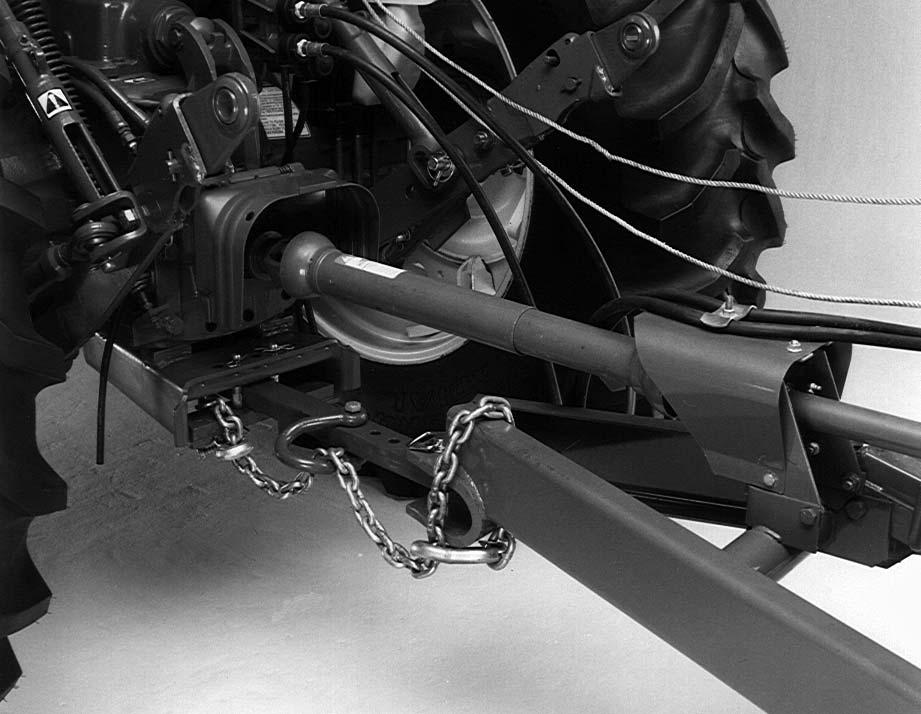
Safety Chains
If the Spreader is going to be transported on public highways, a Safety Chain Kit should be installed, per details in the Transporting chapter. The kit includes a safety chain, a clevis and appropriate attaching hardware. Consult your dealer for the proper size safety chain for your individual Spreader.
Shear Bolts
Shear bolts for the apron transmission shear device is contained in a single shear bolt package. The shear bolt package contains (8) 3/8 x 1-1/2″ (9.5 mm x 38 mm) Grade 5 shear bolts and locknuts.
Splash Shield
The Spreader can be equipped with a Splash Shield Kit to prevent high liquid content manure from spilling over the front of the Spreader while traveling to the field. The splash shield can be conveniently attached to the top front edge of the Spreader using the hardware provided.
Liquid Sides
Liquid sides are available for model 1177, 1217 and 1287 Spreaders. They will eliminate the many problems occurring when hauling soupy manure to the field in a box Spreader. The liquid sides must be used with the hydraulic endgate. The Litter Pan Kit should also be used for maximum effectiveness.
Hydraulic Feed Control
This option allows the operator to hydraulically control the apron speed quadrant from the tractor cab.
With this kit, the feed control quadrant is stroked by the cylinder. With each stroke, the quadrant is advanced. An indicator decal indicates which feed notch is engaged. After advancing the quadrant, the cylinder should be returned to the starting position. This allows the quadrant to rotate backward slightly against the stop.
NOTE: If the Spreader is equipped with both a hydraulic endgate and hydraulic feed control, the tractor used must have dual hydraulic outlets to operate two hydraulic cylinders.
SECOND BEATER & DRIVE ASSEMBLY
As needed, the Spreader can be equipped with a second beater and drive assembly. The beater and drive assembly is designed to be installed on a Spreader to improve spreading high-piled solid manure.
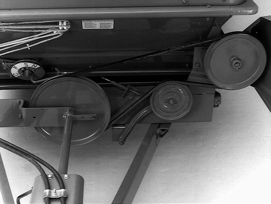
Slow Speed Apron Sprocket
A slow speed apron drive sprocket is available through service parts. The sprocket will slow the speed of the apron for lighter applications of manure.
Speeds will be slowed from 4.5 fpm (137 cm/min) to 2.2 fpm (68 cm/min) on the 1177, 1217 and 1287 model Spreaders, and from 4.6 fpm (140 cm/min) to 3.0 fpm (91 cm/min) on the 1410 model Spreader in the slow speed position.
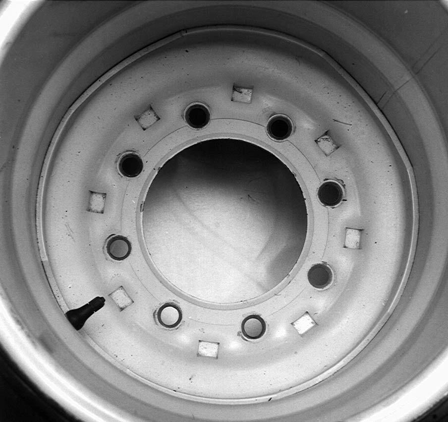
WHEELS & WHEELS WITH TIRES
The following is a listing of the various wheels and wheels with tires combinations for the various model
Spreaders:
Set of two 8 x 20″ rims (1177 & 1217 models only)
Set of two 11.00 x 22.5 recapped tires on 8 x 22.5″ rims (1177 & 1217 models only)
Set of two 16.5L x 16.1 10-ply flotation tires on W14 rims (1217 model only)
Set of four 8 x 20″ rims (1287 model only)
Set of four 11.00 x 22.5 recapped tires on 8 x 22.5″ rims (1287 & 1410 models)
Set of four 16.5L x 16.1 10-ply flotation tires on W14 rims (1287 & 1410 models)
Transport Lighting Kit
NOTE: If the Spreader is to be transported on public highways, a Transport Lighting Kit should be installed.
An accessory Transport Lighting Kit is available for all Spreader models. It includes lights, wiring harness and installation instructions.
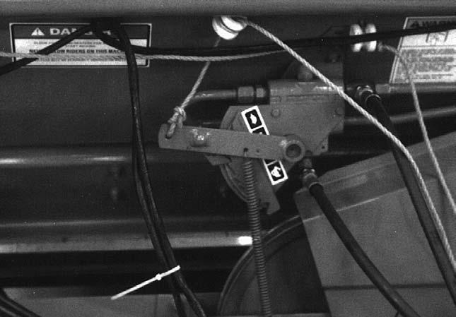
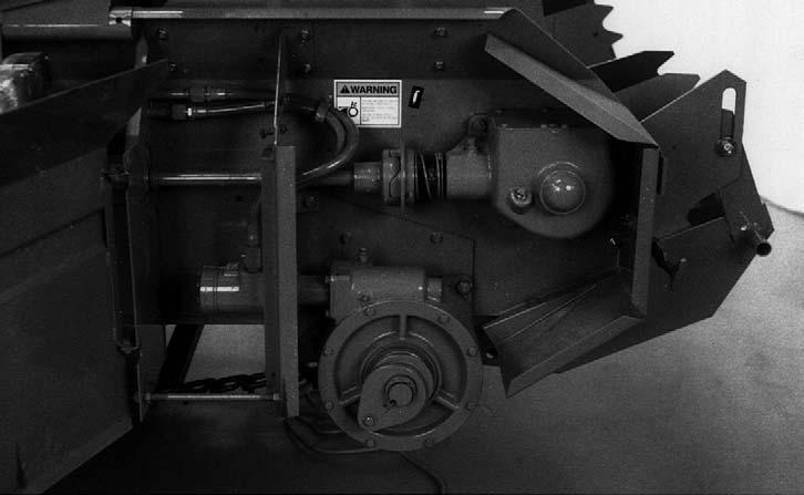
Chapter 15 Decal Locations
General Information
Decal locations information is provided to assist in the proper selection and application of new decals, in the event the original decals become damaged or the machine is repainted. Refer to the listing for the illustration reference number, part number, description and quantity of each decal provided in the kit. Refer to the appropriate illustrations for replacement locations.
NOTE: Refer to the SAFETY chapter for the specific information provided on the various safety decals furnished in the decal kit(s).
To ensure proper selection for correct replacement decals, compare the various close-up location photographs to your machine BEFORE starting to refinish the unit. Then circle each pictured decal (applicable to your machine) while checking off its part number in the listing. After you have verified all the decals needed for replacement, set aside unneeded decals for disposal.
New Decal Application
Surfaces MUST be free from dirt, dust, grease and other foreign material before applying the new decal. To apply a solid-formed decal, remove the smaller portion of the decal backing paper and apply this part of the exposed adhesive backing to the clean surface while maintaining proper position and alignment. Slowly peel off the other portion of the backing paper while applying hand pressure to smooth out the decal surface.
Warning
ALWAYS observe safety rules shown on decals. If decals become damaged, or if the unit is repainted, replace the decals. If repainting, BE SURE that ALL decals from the kit(s) that apply to your machine are affixed to your unit.
The decal kit number for the 1177, 1217, 1287 and 1410 Manure Spreaders is 143383. The kit includes the following:
01145216Reflector/Red Strip (2 places) (3 on 1410 units with upper beater guard, not shown)
02145217Reflector/Amber (2 places 1177 & 1217, 3 places 1287 & 1410)
03091444DANGER - Rotating Component
04093020Lubrication Symbol
05093366IMPORTANT - Store Manual Here
06093367WARNING - Owner’s Responsibility & Read Manual
07093373WARNING - General Safety Precautions
08093457WARNING - Keep Door Closed (2 places) (3 places on units with upper beater)
09094913GEHL 3-1/4 x 15-1/4″
10142984540 RPM
1430021000 RPM
11142985Keep Well Lubricated
12143000Indicator Arrow
13143001150 ft-lb Wheel Bolt torque (HD wheels)
14143003Apron Speed Selector Control (hydraulic apron drive models)
15143004Apron Speed Selector Control (standard PTO apron drive models)
16143005DANGER - NO RIDERS
17143008120 ft-lb Wheel Bolt torque (std wheels)
The following decals are not included in the above kit but may be needed to complete the decaling of your unit.
18094914GEHL 5 x 23-1/2″ (2 places on 1177, 1217 & 1287)(both sides)
122617GEHL 6.9 x 32-1/2″ (2 places on 1410) (both sides)
191430141177 (2 places 1177 ONLY)
1430151217 (2 places 1217 ONLY)
1430161287 (2 places 1287 ONLY)
1432431410 (2 places 1410 ONLY)
Paint Notice
Use this list to order paint for refinishing:
906315One Gal. AG Red
906324One Qt. Light Grey
9063166 (12 oz. Spray Cans) AG Red
9063256 (12 oz. Spray Cans) Light Grey


AAdjustments, 27–31
Application rate, 20
Apron Controls, 14
Attaching to the tractor, 22 B
Beater Controls, 14 C
Checklists, 5–7
Controls & Safety Equipment, 14–17
Covers, Shields & Guards, 15 D
Decal Application, 56
Decal Locations, 56–58
Decal Set and list, 56
Drive Belt adjustment, 27 replacement, 27
Drive Chain lubrication, 32 E
Emergency shutdown, 21 F
Feed Control, adjustment, 29
Feed Control Positions hydraulic drive, 25 mechanical drive, 24
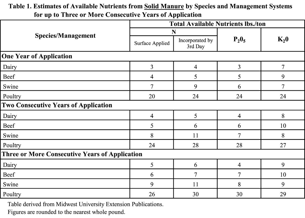
Fertilizer value, 18
GGearbox Drive Chains, adjusting, 29
Grease Fitting locations, 33
Greasing, 32
Guards & Shields, 15
HHighway Transport Lighting, 40
Hydraulic Apron Control, 14
Hydraulic Endgate, 15
Hydraulic Feed Control, 15 I
Inflation pressures. See Tire pressures
Introduction, 2
Jack, 15
Loading Spreader, 24
Lubrication, 32–36 M
Mandatory Safety Shutdown Procedure, 8
Manual Apron Control, 14
Model number record, 5, 7 N
Nutrient value. See Fertilizer value
Oiling, 32
OOiling locations, 33
Operation, 18–26 general information, 21 hydraulic drive machines, 26 mechanical drive machines, 26
Operator’s Manual storage, 2
Optional Features & Accessories, 54–55
Hydraulic Endgate, 54–55
Hydraulic Feed Control, 54–55
Litter Pan, 54–55
Safety Chains, 54–55
Second Beater, 54–55
Shear Bolts, 54–55
Slow Speed Apron Sprocket, 54–55
Slurry Sides, 54–55
Splash Shield, 54–55
Transport Lighting Kit, 55
Wheels & Wheels with Tires, 55
PPaint Notice, 56
PTO Conversion
Model 1410, 540 RPM , 49
Models 1177, 1217 & 1287, 1000 RPM, 38
RReflector, 40
SSafety, 8–13
Safety Chain, 16, 40
Serial number record, 5, 7
Service, 37–39
Set−up & Assembly, 45–53
Shear Bolt, replacement, 29
Single Axle Wheel mounting, 45
SMV (Slow Moving Vehicle) Emblem, 40
SMV Emblem & Reflectors, 16
Specifications, 3
Spreading, 25
Storage, 41
TTable Of Contents, 1
Tandem Axle Wheel mounting, 46
Telescoping PTO Locking Coupler, 16
Telescoping PTO Shields, 16
Tire Pressure, 45
Tire pressures, 37
Tractor hookup, 21
Transmission lubrication, 32
Transmission oil locations, 33
Transport Lighting. See Transport Lighting
Transport lighting, 40
Transporting, 40
Troubleshooting, 42–44
UUnplugging, 25
Upper Beater Drive Chain, adjusting, 30
Warranty, 2
WWheel Bearings, adjusting, 30
Wheel Lug torque, 37
Torque Specifications
NOTE: Use these torque values when tightening GEHL hardware (excluding: locknuts and self-tapping, thread-forming and sheet metal screws) unless specified otherwise.
All torque values are in Lb-Ft, except those marked with an *, which are Lb-In.
(For metric torque value Nm, multiply Lb-Ft value by 1.355 or Lb-In value by 0.113)