7 minute read
CHAPTER 4 SAFETY


The above Safety Alert Symbol means ATTENTION! BECOME ALERT! YOUR SAFETY IS INVOLVED! It stresses an attitude of ‘‘heads up for safety’’ and can be found throughout this Operator’s Manual and on the machine itself.
BEFORE YOU ATTEMPT TO OPERATE THIS EQUIPMENT, READ AND STUDY THE FOLLOWING SAFETY INFORMATION. IN ADDITION, MAKE SURE THAT EVERY INDIVIDUAL WHO OPERATES OR WORKS WITH THIS EQUIPMENT, WHETHER FAMILY MEMBER OR EMPLOYEE, IS FAMILIAR WITH THESE SAFETY PRECAUTIONS.
Our Company ALWAYS takes the operator and his/her safety into consideration when designing its machinery and guards exposed moving parts for his/her protection. However, some areas cannot be guarded or shielded in order to assure proper operation. In addition, this Operator’s Manual, and decals on the machine, warn of additional hazards and should be read and observed closely.
Danger
‘‘DANGER’’ indicates an imminently hazardous situation which, if not avoided, will result in death or serious injury.
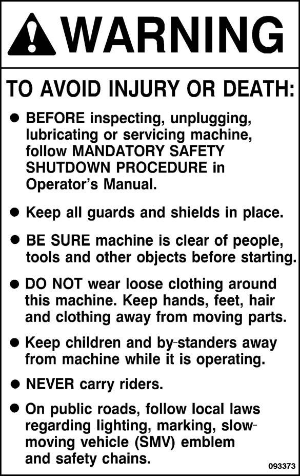
Warning
‘‘WARNING’’ indicates a potentially hazardous situation which, if not avoided, could result in death or serious injury.
Caution
‘‘CAUTION’’ indicates a potentially hazardous situation which, if not avoided, may result in minor or moderate injury. May also alert against unsafe practices.
Mandatory Safety Shutdown Procedure
BEFORE unclogging, cleaning, adjusting, lubricating or servicing the unit:
1.Disengage the tractor PTO and the remote hydraulic supply.
2.Shut off the tractor engine, remove the ignition key and take it with you.
3.Wait for all movement to stop.
4.Remove the telescoping drive and ALL power connections from the tractor.
ONLY when you have taken these precautions can you be sure it is safe to proceed. Failure to follow the above procedure could lead to death or serious bodily injury.
Additional Safety Reminders
Some photographs, used in this manual, may show doors, guards or shields open or removed for illustration purposes ONLY. BE SURE that all doors, guards and shields are in their proper positions and securely attached BEFORE operating this unit.
ALWAYS wear safety glasses with side shields when striking metal against metal. In addition, it is recommended that a softer (chip-resistant) material be used to cushion the blow. Failure to heed could result in serious injury to the eyes or other parts of the body.
ALWAYS follow state and local regulations regarding use of a safety chain and transport lighting when towing farm equipment on public highways. Restrict highway towing speeds to 20 mph (32 km/h) maximum. BE SURE to check with local law enforcement agencies for your own particular regulations.
Only a safety chain (NOT an elastic or nylon/plastic tow strap) should be used to retain the connection between the towing and towed machines, in the event of separation of the primary attaching system.
NEVER use your hands to search for hydraulic fluid leaks. Use a piece of paper or cardboard. Escaping fluid under pressure can be invisible and penetrate the skin, causing a serious injury. If any fluid is injected into your skin, see a doctor at once. Injected fluid MUST be surgically removed by a doctor familiar with this type of injury or gangrene may result.
NEVER use too small of a tractor. A small tractor may be able to pull the unit, but the tractor would not be heavy enough for adequate traction and braking to control the weight of the heavy Spreader on hills and for steering. NEVER use smaller than the recommended size tractor.
To ensure continued safe operation, replace damaged or worn-out parts with genuine GEHL service parts, BEFORE attempting to operate this equipment. Our Company does not sell replacement tires. In addition, tire mounting, service or inflation can be dangerous. Whenever possible, trained personnel should be called to service and/or mount tires, following the tire manufacturer’s instruction. If you do not have such instructions, contact your tire dealer or our Company. In any event, to avoid possible fatal or serious injury, follow the specific directive given in the Service chapter of this manual.
BE SURE rotating shields on telescoping PTO driveline turn freely BEFORE starting tractor engine.
BE SURE the hitchjack locking pin is completely engaged and that the machine is properly blocked and prevented from rolling BEFORE disconnecting the unit from the tractor.
Block the Spreader so it will not roll after it is disconnected from the tractor.
To avoid injury, stay out of the Manure Spreader box. If entrance into the box is required, BE SURE to exercise the MANDATORY SAFETY SHUTDOWN PROCEDURE BEFORE going in.
MANURE GAS IS A DEADLY KILLER! Good safety practices dictate that you NEVER enter a manure pit alone. BE SURE someone else is around to help you out in an emergency. Also, BE SURE to wear a selfcontained breathing apparatus, if you must enter a liquid manure pit.
REMEMBER, it is the owner’s responsibility for communicating information on the safe use and proper maintenance of this machine.


CHAPTER 5 CONTROLS & SAFETY EQUIPMENT
This machine is provided with features for operator safety and convenience.
Warning
Become familiar with and know how to use ALL safety devices and controls on this machine BEFORE attempting to operate the unit. Know how to STOP machine operation BEFORE starting it.
BEATER & APRON CONTROLS
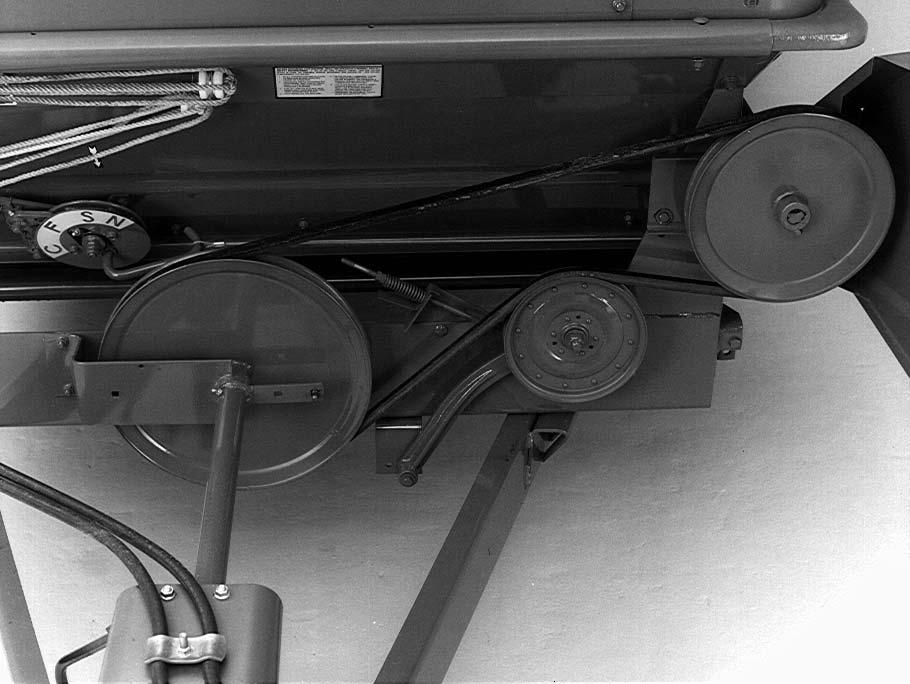
Manual Apron Control Units (Fig. 1)

Manual apron control Gehl box Spreaders feature a beater and apron speed control that allows the conveyor apron to be operated at two speeds for unloading and to stop the beater(s) for box cleanout. The control mechanism is linked to the tractor by a control rope. A decal on the control quadrant shows the operator what control position has been selected.

NOTE: Manual apron control box Spreaders can be provided with a slow speed sprocket on the apron transmission drive shaft, which will reduce slow apron speed for spreading slurry grade manures. The sprocket is available from your dealer.
NOTE: BEFORE loading or after unloading and cleaning out the Spreader box, reset the indicator to the “neutral” position.
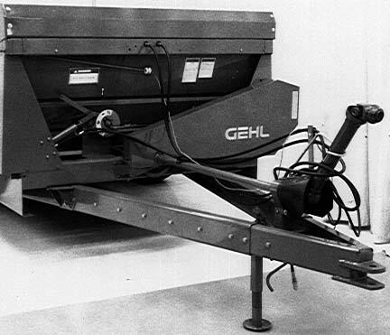
Hydraulic Apron Control Units (Fig.
Hydraulic apron drive-equipped Spreaders feature a hydraulic motor-driven transmission. Oil flow to the drive motor is controlled by the amount of oil flow from the tractor remote outlet and the adjusted position of the 9 position control valve quadrant on the Spreader. Slow-Fast adjustment of the regulator is controlled by a control rope on the front of the Spreader. Position of the regulator is visually displayed the control valve lever.
GUARDS & SHIELDS (Figs. 1, 4)
Warning
BEFORE performing any work on the unit and BEFORE removing or opening any guards or covers, BE SURE to follow the MANDATORY SAFETY SHUTDOWN PROCEDURE (page 8). Replace ALL guards and covers BEFORE resuming operation.
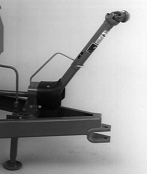
JACK (Fig. 1)
A jack is furnished with the Spreader to support the machine when the tractor is disconnected, as well as to facilitate aligning the hitch clevis with the tractor drawbar for hookup.

When the jack is not being used to support the Spreader, it can be pivoted up to the “storage” position.
Warning
MAKE SURE the locking pin is properly seated into the holes through the jack tube frame and the plate on the Spreader A-frame, BEFORE the tractor is disconnected.
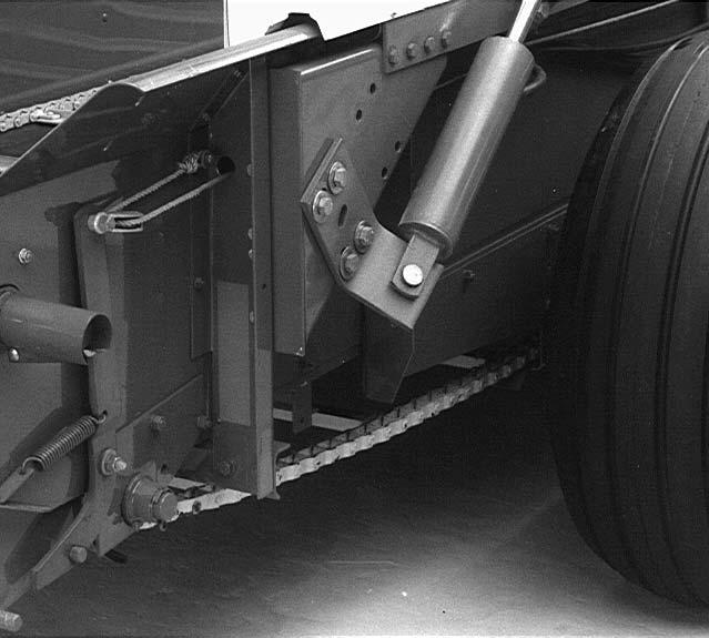
HYDRAULIC FEED CONTROL (OPTIONAL)(Fig. 3)
This option is for the operator who wants to control the apron speed quadrant from the tractor cab. With this kit, the feed control quadrant is stroked by the cylinder. With each stroke, the quadrant is advanced. An indicator decal indicates which feed notch is engaged. After advancing the quadrant, the cylinder should be returned to the starting position. This allows the quadrant to rotate backward slightly against the stop.
NOTE: If the Spreader is equipped with other hydraulic options, the tractor used must have enough hydraulic outlets to operate all options.
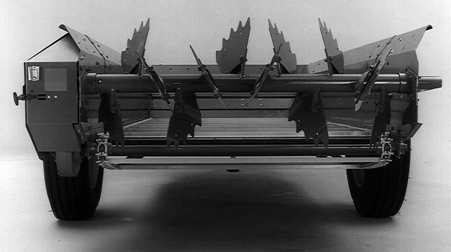
HYDRAULIC ENDGATE (OPTIONAL) (Fig. 4)
The Manure Spreader can be equipped with an optional hydraulic endgate which uses tractor-operated hydraulic cylinder(s) to raise and lower the endgate. The endgate should be ordered and installed on any unit that is frequently used to haul manure over a public highway.
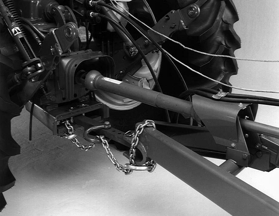
SAFETY CHAIN (Fig. 5) WARNING
ALWAYS follow state and local regulation regarding use of a safety chain and transport lighting when towing farm equipment on public highways. ONLY a safety chain (NOT an elastic or nylon/plastic tow strap) should be used to retain the connection between the towing and towed machines, in the event of separation of the primary attaching system. BE SURE to check with local law enforcement agencies for your particular regulations.
tor strips are also provided on the rear and front outermost edges of the unit.
NOTE: If the Spreader is to be transported on public highways, an accessory Transport Lighting Kit can be installed.
Warning
NEVER use too small of a tractor. A small tractor may be able to pull the unit, but the tractor would not be heavy enough for adequate traction and braking to control the weight of the heavy Spreader on hills and for steering. NEVER use smaller than the recommended size tractor.
As needed, the Spreader should be equipped with a safety chain for transporting the unit on a public highway. The chain should be routed as shown in Figure 5. Refer to the Transporting chapter of this manual for additional information.

SMV EMBLEM, REFLECTORS & TRANSPORT LIGHTING (Figs. 3 & 6)
Gehl Box Type Manure Spreaders are equipped with a Slow-Moving Vehicle (SMV) emblem mounting bracket on the left rear corner of the unit. The SMV emblem MUST be purchased separately. Red and amber reflec-
Telescoping Pto Drive
(See Fig. 1)
The telescoping PTO drive is designed to rotate freely inside the drive shield tubes.
The telescoping PTO drive is provided with a springloaded locking device on each end to positively lock the drive connection onto the tractor PTO shaft and the Spreader drive input shaft. Depress the locking device against the spring tension, and slide the yoke onto its respective drive shaft. Release the locking device and move the yoke ahead or back until the lock engages into the groove of its respective shaft.
Warning
BE SURE the telescoping drive rotates freely inside the drive shield tubes at all times. These tubes MUST NOT be anchored.
NOTE: For your convenience, when the Spreader is disconnected from the tractor, the PTO can be placed over the PTO hanger provided.