11 minute read
CHAPTER 11 STORAGE

Because a Manure Spreader is generally a year-round implement, it should be in ready-to-operate condition at all times. Several provisions have been designed into the Manure Spreader to enable it to be used in cold, moderate and warm temperatures. The most important factor for continuous proper operation is lubrication. Routine lubrication should be repeated more frequently in both temperature extremes.
NOTE: When operating the Spreader in freezing temperatures, the unit should be stored inside, if possible. Refer to Operation chapter for special operating procedures in freezing temperatures.
If after being used the Spreader is not to be used for some time, perform the following steps to ensure long life and trouble free start-up for the next usage:
1.Remove all manure from the inside and outside of the Spreader. Wash the Spreader thoroughly with water from a hose or pressure washer.
2.Perform all lubrication as called out in the Lubrication chapter.
3.Repair or replace all worn or missing parts. Paint any surfaces where bare metal has been exposed.
4.If possible, store the Spreader indoors and remove weight from the tires.
Chapter 12 Troubleshooting
NOTES This Troubleshooting guide presents problems, causes and suggested remedies beyond the extent of loose, worn or missing parts, and it was developed with the understanding that the machine is in otherwise good operating condition. Refer to the index at the back of this manual for chapter and topic page references. BE SURE to follow the MANDATORY SAFETY SHUTDOWN PROCEDURE (page 8) BEFORE making any adjustments or repairs.
Miscellaneous Problems
Problem Cause Remedy
Apron chain breaking. Freezing conditions. Always be sure apron is NOT frozen to floor before starting PTO. Bent apron slats. Replace bent slats.
Loose apron chain. Adjust apron chain.
Bending apron adjusting idler bracket and apron slats.
Loose apron chain. Adjust apron chain.
Apron frozen to chain return guides. Be sure apron is free to move BEFORE operating.
Excessive wear or corrosion of apron chain. Lack of lubrication. Oil per details in Lubrication chapter.
Corrosive conditions. Lubricate more frequently.
Shear bolt failure - apron drive. Freezing conditions. Always be sure apron is NOT frozen to floor before starting PTO. Overloading. Load according to weight of manure. Do NOT exceed maximum net load.
Incorrect shear bolt being used. Replace with correct shear bolt. Hauling mixture of heavy manure and dirt. Wet sides and floor with water every few loads.
Feed control overspin. Center pivot bolt loose. Tighten and secure with two jam nuts.
Clutches not aligned. Adjust per details in Adjustments chapter.
Feed control not going far enough. Dry or corroded center pivot. Clean and grease. Springs stretched. Replace springs. Center pivot too tight. Loosen, but tighten jam nuts against each other.
Drive Belt Problems
PROBLEM CAUSE REMEDY
Drive belt slippage. Incorrect belt adjustment. Adjust per details in Adjustment chapter.
Misaligned sheaves. Align sheaves.
Foreign material on belt. Clean belt. MAKE SURE drive belt shield is properly installed. Tractor engine speed too high. Engage PTO slowly with tractor engine at moderate speed.
Manure on beaters. Do NOT load manure on beaters. Freezing conditions. Always be sure apron is NOT frozen to floor before starting PTO.
Overloading. Load according to weight of manure. Do NOT exceed maximum net load.
Hauling mixture of heavy manure and dirt. Wet sides and floor with water every few loads.
Endgate Problems
PROBLEM CAUSE REMEDY
Manure is leaking past endgate. Seal damaged or worn. Replace seals. Bent or damaged endgate. Replace or replace endgate.
Endgate does NOT raise. Insufficient oil pressure. Check oil supply and connections. Cylinder(s) leaking. Repair cylinder(s).
Endgate is frozen down. Free endgate.
CHAPTER 13 SET-UP & ASSEMBLY
General Information
The following procedures should be performed inside an enclosed workshop that is equipped with the proper tools and an overhead hoist. Although the procedures imply a single set-up person, two people can and will be able to assemble the components to the machine more quickly and easily.
The parts shipped inside the Spreader should be removed first. This will reduce the weight of the Spreader for handling.
IMPORTANT: Be careful not to damage the Spreader floor when lifting the parts from the Spreader box.
IMPORTANT: If an overhead hoist is used to lift the Spreader, BE SURE to use a long lifting chain or Spreader bar when hoisting to avoid distorting the Spreader box.
After removing the Spreader from the shipping position, place the Spreader on blocks
NOTE: Block up the Spreader so the bottom of the frame is at least 18″ (457 mm) above the ground.
TIRES, WHEELS & AXLES
If the Spreader is ordered without mounted tires, tire mounting should only be performed by a qualified tire manufacturer’s installer, or by properly trained personnel following the manufacturer’s instructions. All truck-type tires MUST be mounted with inner tubes.
Warning
Tire mounting, inflating, repair and replacements should only be performed by a qualified tire manufacturer’s representative, or by properly trained personnel following the tire manufacturer’s instructions. Refer to the Service chapter for additional details.
Before installing the wheels, clean the paint from the lug bolt chamfers, Figure 28, on each wheel rim.
IMPORTANT: Do not use an impact wrench to tighten the wheels. Over-torquing the wheels will distort the rims, and the lug bolts will not remain tight.
Tire Pressure
Inflate the tires to 32 PSI (221 kPa) for 16.5L x 16.1 flotation tires, 35 PSI ( 241 kPa) for 19L x 16.1 flotation tires, for 50 PSI (345 kPa) for 10.00 x 20 truck tires, or 60 PSI (414 kPa) for 11.00 x 20 or 11.00 x 22.5 truck tires.
Single Axle Models (1177, 1217)
IMPORTANT: A Spreader with used or recapped truck tires that have inner tubes with long valve stems MUST be mounted with the valve stems facing the outside of the Spreader
Place the jack in the park position. Install the wheels with the eight wheel lug bolts and torque the bolts to 120 ft. lbs. (163 N·m). Heavy duty wheels with 11.00″ x 22.5″ tires use eight Grade 8 cap screws and flat washers. Torque to 150 ft. lbs. (203 N·m). Then lower the Spreader to the ground.
If still attached, remove the chains used to unload the Spreader.
Tandem Axle Models (1287 & 1410) (Figs. 29-32)
NOTE: A Spreader with used or recapped truck tires that have inner tubes with long valve stems MUST be mounted with the valve stems facing the outside of the Spreader

Chain Guide & Wheels (1287 ONLY)
Apron chain guides are used as tandem axle shipping brackets as shown in Figure 29. Remove the apron chain guide from the shipping position.


Place the jack in the park position. Install the wheels with the eight wheel lug bolts and torque the bolts to 120 ft. lbs. (163 N·m). Heavy duty wheel with 11.00″ x 22.5″ tires uses eight Grade 8 cap screws and flat washers. Torque to 150 ft. lbs. (203 N·m). Then lower the Spreader to the ground.
If still attached, remove the chains used to unload the Spreader.
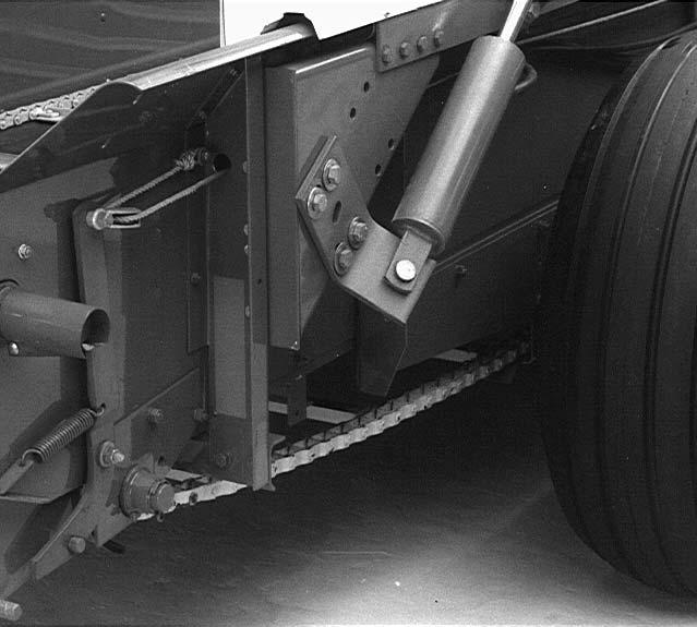
Install the chain guide shown in Figure 30, using 1/2″ x 1″ (12.7 mm x 25 mm) cap screws, lock washers, and nuts. Adjust the apron chain so it clears the underside of the axle 1/2″ to 1-1/2″ (12.7 mm to 38 mm).
Model 1410
Clean the wheel beam pivot pin and lubricate with a good grade of lithium-based grease.
Install a washer on the pivot pin and slide the pin into the Spreader axle assembly. Make sure the longer section of the wheel beam is to the front of the Spreader as shown in Figure 31.
Install spacer washers on the pivot pin, Figure 32, as needed, leaving enough room to install two square washers and a 7/16″ x 4-1/2″ (11.1 mm x 114 mm) cap screw and locknut. Install the cap screw with the nut on top of the pivot pin as shown in Figure 32.
Install the axle on the right side in a similar manner.
IMPORTANT: The cap screw in Figure 32 MUST be installed with the threads and nut on top of the pivot pin as shown. If installed backwards with the nut on the bottom of the pivot, the extra thread length will catch on the moving apron slats and damage both the slat and apron assembly.
NOTE: A Spreader with used or recapped truck tires that have inner tubes with long valve stems MUST be mounted with the valve stems facing the outside of the Spreader
Install the wheels with the eight wheel lug bolts and torque the bolts to 120 ft. lbs. (163 N·m). Heavy duty wheels with 11.00″ x 22.5″ tires uses eight Grade 8 cap screws and flat washers. Torque to 150 ft. lbs. (203 N·m).
SHIPPING BRACKETS (1177, 1217 & 1287 ONLY)
Remove and discard the lower two shipping brackets at the rear of the Spreader. Install a new 1/2″ x 1-3/4″ (12.7 mm x 44 mm) cap screw, lock washer, and nut at the lower front corner of the apron drive gearbox. Torque it to 66 ft. lbs. (89 N·m).


Remove the bolts, holding the upper shipping brackets and plank. Replace the four bolts with 3/8″ x 3/4″ (9.5 mm x 19 mm) cap screws and flange nuts. Remove the front wood shipping support. If a front splash guard is not to be installed, use plastic plugs or 3/8 ″ x 3/4″ (9.5 mm x 19 mm) round-head, short square neck bolts and flange nuts to fill the holes.
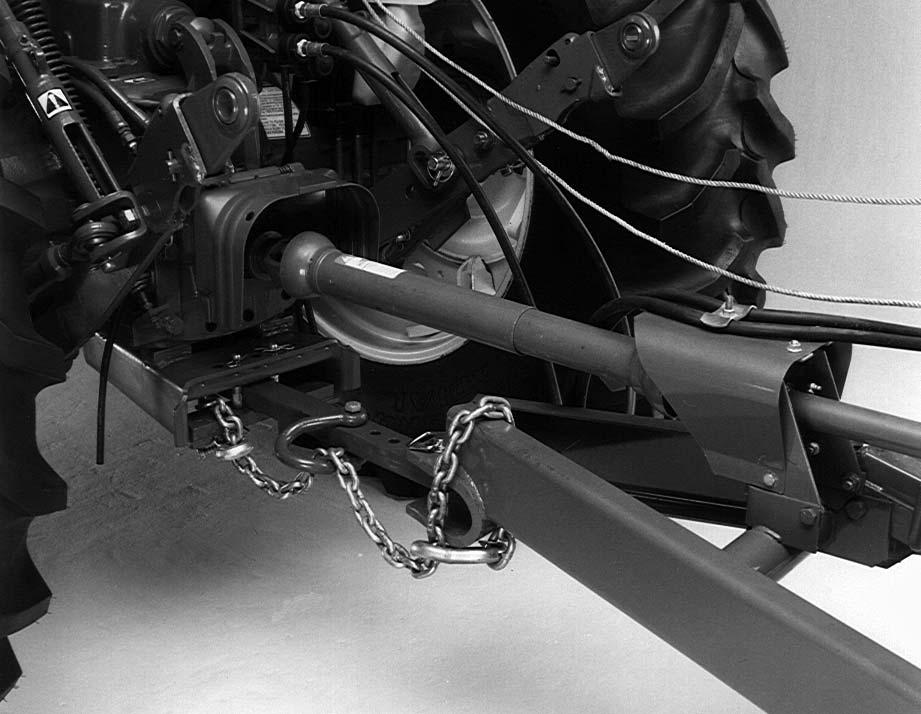
HITCH (1410 ONLY)
NOTE: All of the 1/2″ (12.7 mm) cap screws used to assemble the hitch should be installed with a hardened flat washer under both the head of the bolt and nut. Install the bolts with the heads to the outside to reduce tire damage when turning. Do not tighten any hardware until assembly is complete. Install hitch channels, Figure 33, with a cap screw and nut as shown in Figure 34. Leave the nut as loose as possible to allow the hitch channels to be spread as far apart as possible.
1 - Chain guide hardware (may need to be loosened)
2 - Cap screw and nut (install loose)
Slide the other rail against the hitch and attach with 1/2″ x 1-1/2″ (12.7 mm x 38 mm) cap screws, nuts and two flat washers as shown in Figure 35. Attach side brackets, Figures 35 and 36, to the hitch rails with 1/2″ x 1-1/2″ (12.7 mm x 38 mm) cap screws, nuts and flat washers. Attach the side brackets, Figure 36, to the Spreader with 5/8 ″ x 1-3/4″ (15.9 mm x 44 mm) cap screws, locknuts, and flat washers.
3 2
1 - Hitch side brackets


2 - 1/2″ x 1-1/2″ (12.7 mm x 38 mm) cap screws, flat washers and nuts
3 2 1 2
3 - 5/8″ x 1-3/4″ (15.9 mm x 44 mm) cap screws, flat washers and nuts
Fig. 36
2 - 3/8″ x 1-1/4″ (9.5 mm x 32 mm) cap screws, flange nuts
3 - Chain guide hardware
3 2 1 4 2 2
3 - 3/8″ x 1″ (9.5 mm x 25 mm) cap screws, flange nuts (4) for PTO shaft bearing housing
4 - 3/8″ x 1″ (9.5 mm x 25 mm) cap screws, flange nuts (2) for shaft support
Fig. 38
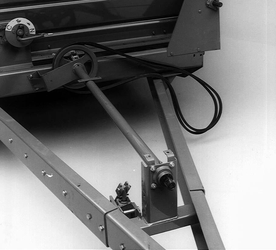
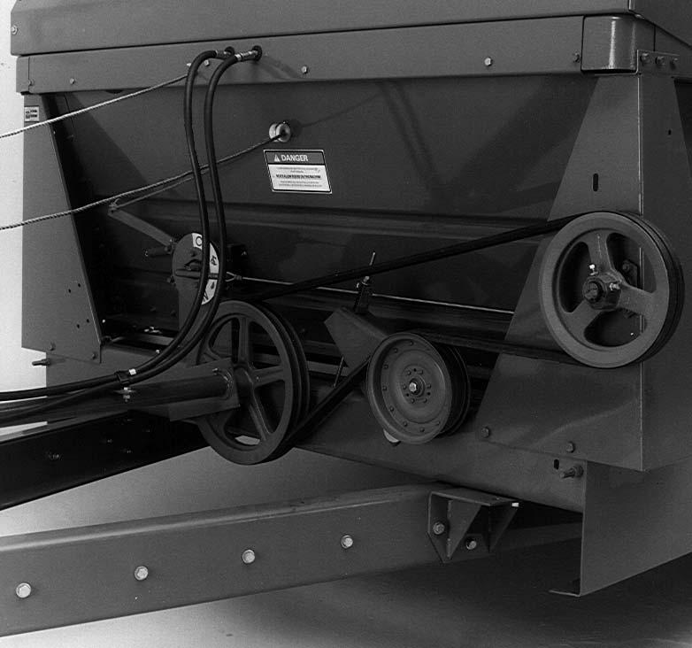
Locate the PTO shaft bearing housing to the front side of the bearing support and install 3/8″ x 1″ (9.5 mm x 25 mm) cap screws and flange nuts as shown in Figure 38, to retain the PTO shaft bearing housing. Place the drive belt on the pulley as shown and attach the shaft support to the main frame with two 3/8″ x 1″ (9.5 mm x 25 mm) cap screws and flange nuts.
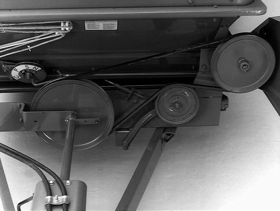
Install a square key in the propeller shaft and install driven sheave, Figure 39. Use a straightedge to align it with the drive sheave. Secure the driven sheave to the propeller shaft with two 3/8″ x 3/4″ (9.5 mm x 19 mm) set screws and jam nuts.
Install idler J-bolt, Figure 39, through the frame and the belt tension idler bracket. Install the spring tension gauge, spring, 3/8″ (9.5 mm) flat washer, and two 3/8″ (9.5 mm) nuts. Tighten the nuts until the spring is compressed to the length of the spring gauge. Check the alignment of the idler pulley and shim if necessary.
2.Remove the cotter key, slotted nut, and washer securing the drive sheave to the rear of the drive shaft.
3.Install the large 15″ (381 mm) sheave on the rear of the drive shaft. Install the flat washer and castellated nut. Tighten securely. Then back off the nut to the nearest set of castellations and install the cotter key.
4.Install the 11″ (279 mm) sheave on the propeller shaft as shown. Align with the drive sheave and secure with two 3/8″ x 3/4″ (9.5 mm x 19 mm) set screws and jam nuts, Figure 40.
5.Reinstall the drive belts. Tighten the nuts on the belt idler J-bolt, until the spring is compressed to the length of the spring gauge.
NOTE: If the Spreader is changed for 540 PTO operation, obtain a 143048 front PTO assembly from the Gehl Parts Department.

1 - Driven sheave 15″ (381 mm)
2 - Drive sheave 11″ (279 mm)
3 - 3/8″ x 3/4″ (9.5 mm x 19 mm) set screws and jam nuts
5 - Spring tension gauge, spring, flat washer and nuts
NOTE: The drive shaft has been assembled with the 11″ (279 mm) drive sheave for 1000 RPM PTO tractors. If the Spreader is to be assembled for 540 RPM, the following procedure to convert it must be used.
1.Remove the drive shaft from the Spreader.
1 - 15″ (381 mm) sheave
2 - 11″ (279 mm) sheave
3 - 3/8″ x 3/4″ (9.5 mm x 19 mm) set screws and jam nuts
Rope
Thread one end of the control rope through the porcelain rope guide and through the hole in the control lever as shown in Figure 40. Tie a knot at the end of the rope.
NOTE: On hydraulic drive machines, tie the rope to the lever using a large knot. The knot acts as a stop to prevent the pawl from disengaging. When the rope is pulled, the tip of the pawl should not go past the point shown in Figure 41.


PTO & PTO SHIELD
Install the PTO assembly as shown in Figure 43, to the drive shaft securing with a 1/4″ x 2-1/2″ (6.4 x 64 mm) Grade 8 cap screw and locknut.
SHIELD (1410 ONLY)
Install the main drive shield as shown in Figure 42. Secure the shield with a 3/8″ (9.5 mm) nut, lock washer, and flat washer or a 3/8″ x 1″ (9.5 mm x 25 mm) cap screw, flat washer, and flange nut in the locations shown.
1 - Implement end of PTO 2 - 1/4″ x 2-1/2″ (6.4 x 64 mm) Grade 8 cap screw and lock nut
Install the PTO shield as shown in Figure 44, securing with two 3/8″ x 3/4″ (9.5 mm x 19 mm) cap screws and flange nuts or two 3/8″ x 3/4″ (9.5 mm x 19 mm) cap screws, flat washers, and flange nuts.
2 - lock and 3/8″ (9.5 mm) nut
1 - PTO shield
2 - 3/8″ x 3/4″ (9.5 mm x 19 mm) cap screws and flange nuts
3 - 3/8″ x 3/4″ (9.5 mm x 19 mm) cap screws, flat washers and flange nuts
PTO HANGER (1177, 1217 & 1287)
1.Install the PTO hanger at the location shown in Figure 44.
2.Assemble the hardware on the inside of the channel as shown in Figure 45, using a 3/8″ x 2″ (9.5 mm x 51 mm) cap screw, three 3/8″ (9.5 mm) flat washers, PTO hanger and two 3/8″ (9.5 mm) flange nuts.
3.Clamp flange nuts, against the PTO channel, such that the PTO hanger is free to rotate.
4.Pivot the PTO hanger up against the PTO shield shown in Figure 44, when supporting the PTO.
5.Fold the hanger down on the drive shaft shield shown in Figure 44, for storage during operation.
PTO HANGER (1410 ONLY)
1.Install the PTO hanger at the location shown in Figure 44.
2.Assemble the hardware on the inside of the channel, as shown in Figure 46, using a 3/8″ x 2″ (9.5 mm x 51 mm) cap screw, two 3/8″ (9.5 mm) thick spacers, a wide spacer, PTO hanger and two 3/8″ (9.5 mm) flange nuts.
3.Clamp flange nuts, against the PTO channel, such that the PTO hanger is free to rotate.
4.Pivot the PTO hanger up against the PTO shield shown in Figure 44, when supporting the PTO.
5.Fold the hanger down on the drive shaft shield shown in Figure 44, for storage during operation.
RUBBER PTO SHIELD (Fig. 47)

1.Install the rubber PTO shield as shown in Figure 47, securing with a 5/16 x 1″ (7.9 mm x 25 mm) cap screw, two flat washers and a lock nut in each of the four locations. BE SURE to place one of the flat washers under the head of the cap screw.
Lubrication
Lubricate the machine carefully as recommended in the Lubrication chapter.