22 minute read
CHAPTER 6 OPERATION


General Information Warning
Read and observe ALL safety decals on the unit BEFORE operating it. Do NOT attempt to operate this equipment until ALL factoryinstalled guards and shields are properly secured in place. BEFORE starting the tractor engine and running the Spreader, review and comply with ALL applicable recommendations set forth in the SAFETY chapter of this manual.
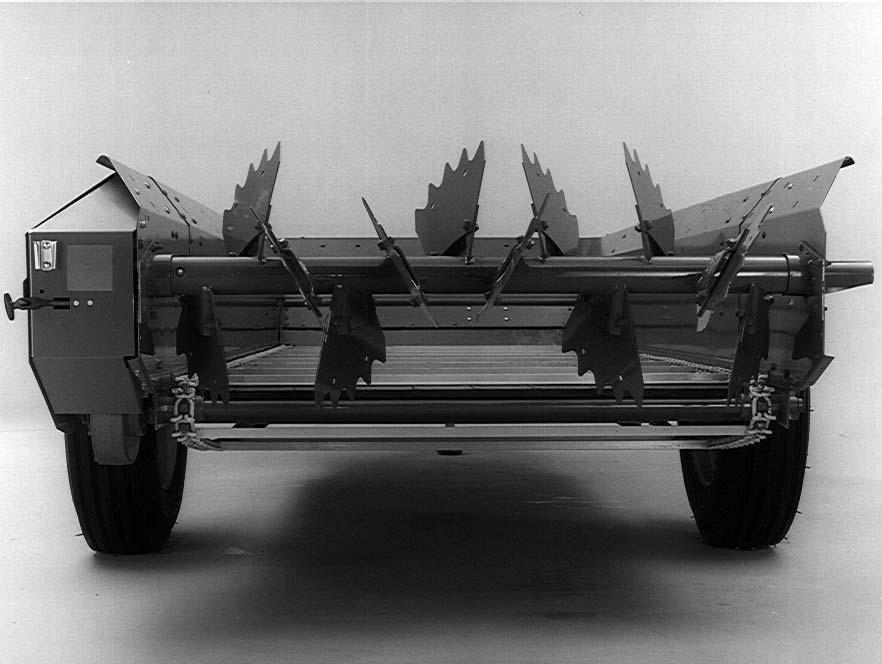
GEHL Box Spreaders are designed and constructed to handle semi-solid and solid manures. Their low profile makes them convenient for loading with barn cleaners, skid loaders or front end loaders. Models feature
Cor-Ten steel box sides, a high density polyethylene tongue and groove plank floor, a beater drive transmission, a two-speed apron drive transmission and shear bolt overload protection on the apron transmission.
Nutrient Value for Crop Production
Different types of manure vary in nutrient content depending upon the animal type and livestock management system. Nutrients contained in manures are not immediately available to crops but are gradually released over time. Therefore, the amount of nutrients that should be credited from manure increases if applications are made to the same field for consecutive years. The N (Nitrogen) credit increases each successive year of application (up to three consecutive years) by approximately 30%. For example, N credits with consecutive applications of surface-applied dairy manure are 3, 4 and 5 lbs./ton N in the first, second, and third or more years of application, respectively (Table 1). Credits for P (Phosphate) and K (Potassium) increase somewhat less.
Nutrient losses from manure can be minimized by incorporating surface applied manure within 72 hours. If manure remains on the soil surface, losses of nutrients may occur to the atmosphere or in runoff.
To determine nutrient credits for manure that has not been analyzed, establish the field manure history and use the table values (Tables 1 & 3). Multiply the manure application rate by the appropriate nutrient content (lbs. per ton or lbs. per 1000 gal.). In situations where the nutrient content of manure has been analyzed, multiply the total nutrient content by the appropriate percent available nutrient value (Table 2) by the application rate.

In summary, using the table information/data in conjunction with soil testing, an application rate can be determined that will fit your nutrient management plan. Assistance may be obtained from your local University Extension office.

Application Rate (Fig. 7)
Several factors influence the rate of manure being discharged. These factors include: the apron drive transmission speed, the ground speed, the type and consistency of the manure and the PTO RPM.
NOTE: Under NO circumstances should the rated 540 or (optional) 1000 RPM of the Spreader be exceeded.
1177, 1217 & 1287 Application Rates in Tons/Acre
1 - 56″ (1422 mm)
2 - Plastic sheeting
3 - 2 x 4’s
Fig. 7: Field-constructed Collection Frame
Assumptions:
(1) - Manure density = 60 lbs./ft3
(2) - Box filled to struck capacity
(3) - Rated PTO speed
The amount of material being applied can be measured by constructing an inside-measured 56″ x 56″ (1422 mm x 1422 mm) collection frame out of 2 x 4’s and plastic sheeting. The amount of material collected on the frame can be removed and weighed to determine how many tons or gallons per acre are being applied.
If the weight of the manure caught on the collection frame weighs 1-1/2 pounds, the number of tons per acre would be:
1 ton/acre x 1-1/2 lbs. = 1-1/2 tons/acre
1410 Application Rates in Tons/Acre
Emergency Shutdown
In an emergency, or in case a foreign object becomes lodged in the rear beater area, STOP Spreader operation IMMEDIATELY by disengaging the tractor PTO. BE SURE to follow the MANDATORY SAFETY
SHUTDOWN PROCEDURE (page 8) when leaving the tractor seat to correct the problem.
General Information
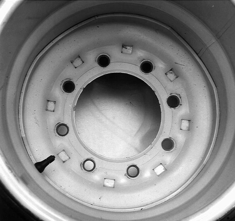
Check for proper assembly and adjustment and make sure all bolts are tightened securely. Torque the wheel bolts to 120 ft. lbs. (163 N·m).
NOTE: Torque the wheel bolts to 150 ft. lbs. (203 N·m) if the heavy-duty wheel rims are used.
IMPORTANT: Retighten the bolts after every other load until the torque does not decrease, and every 300 loads thereafter.
Check the tires and inflate them to the recommended pressure. See the Service chapter for details.
Adjust the tractor hitch and attach the Spreader to the tractor as described in this chapter.
Attach the feed control rope to a convenient point on the tractor, or connect the remote control hoses to the tractor hydraulic outlets.
Lubricate the Spreader completely and check the oil level of the gearboxes.
Operate the Spreader slowly for a period of time to run the chains in and determine that all parts work freely. A tractor of sufficient weight must be used for adequate traction, braking, and steering on hills.
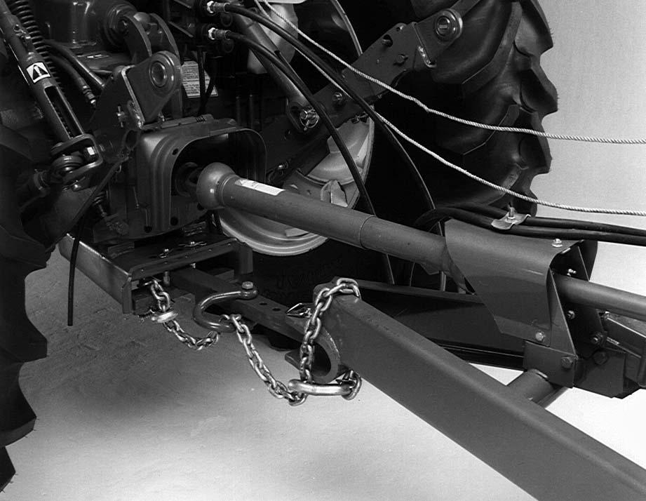
TRACTOR HOOK-UP (Fig. 8)
NOTE: By design, the model 1177, 1217, and 1287 Spreaders can only be properly hooked up to a tractor that has PTO and hitch dimensions conforming to ASAE Standard S203. Horsepower required may vary according to the consistency of manure, ground speed and terrain.
NOTE: By design, when the 540 RPM option is installed on the model 1410, the 1000 RPM dimension (16″) must be retained.
1 - Tractor PTO shaft (tractor MUST comply with ASAE standard S203)
2 - 14″ [356 mm] for 540 RPM operation (16″ [406 mm] for 1000 RPM) measured from tractor PTO shaft to center of hitch bolt
3 - 6 to 12″ (152 to 305 mm) - 8″ (203 mm) preferred
4 - 13 to 17″ (330 to 432 mm) from ground
5 - Tractor drawbar
6 - Locking hitchpin
7 - Hitch clevis
Warning
Use a locking hitchpin (a pin with a positive retaining device) to connect the Spreader to the tractor drawbar.
Proper operation of a loaded Spreader requires a tractor with sufficient horsepower to run the PTO, and suffcient size to counterbalance the weight of a loaded Spreader. Refer to the Specifications chapter for additional information.
These Spreaders could possibly be operated with a smaller tractor, but smaller tractors do not have the traction to handle the bigger loads at normal road speed.
Warning
NEVER use too small of a tractor. A small tractor may be able to pull the unit, but the tractor would not be heavy enough for adequate traction and braking to control the weight of the heavy Spreader on hills and for steering. NEVER use smaller than the recommended size tractor.
Attaching To The Tractor
NOTE: If this unit is connected to a tractor equipped with a clevis style drawbar, the clevis parts shown in dashed lines MUST be removed to prevent damage to the unit driveline. See Fig. 9 for details.
NOTE: Be sure the Spreader drive belt sheaves are arranged for the PTO speed of the tractor.
2.Remove the weight from the jack. Swing the jack to its horizontal storage position and lock it to provide maximum ground clearance.
3.Pull back on the collar and slide the PTO driveline onto the tractor shaft until the balls engage in the groove in the tractor shaft. Release the collar. MAKE SURE that the PTO is locked on the shaft. To remove the PTO, pull back on the collar to unlock the balls and slide the PTO driveline off the tractor shaft.

NOTE: The balls and yoke hub where the collar slides must be free of paint and rust and must be kept lubricated with oil for proper operation.
1.Using a tractor of the proper horsepower range and weight, fasten the Spreader hitch to the drawbar with a 1″ (25 mm) diameter locking hitch pin on 1177, 1217 and 1287 models, and with a 1-1/8″ (29 mm) diameter locking hitch pin on model 1410 so that the pin cannot bounce out.
Warning
Damage to the Spreader or another vehicle, and injury to the operator, may occur if an incorrect pin is used. A safety chain should also be used when traveling on public roadways.
4.Attach the hydraulic hoses to the tractor hydraulic outlets. Keep the hydraulics clean. Always clean the hydraulic hose fittings before connecting them to the tractor hydraulic couplings.
NOTE: On machines with the hydraulic apron drive, refer to Figure 11 and be sure that the hose connected to the bottom of the control valve is pressurized. The hose connected to the tee is the return hose. A check valve at the orbit motor prevents pressurizing the return hose, which would run the apron in reverse.
To provide satisfactory performance of the hydraulic apron drive, the tractor should be capable of producing a hydraulic flow of at least 10 gpm (38 L/min.) at 1750 psi (121 bar).
NOTE: To operate the Spreader with a tractor with closed-center hydraulics, remove tee, Figure 11, from the valve. Plug the valve port from which the tee was removed with a 1/2 ″ (12.7 mm) NPT pipe plug. Install a 1/2 ″ (12.7 mm) NPT pipe cap on the end of the tee. Carefully reposition tube, so a hose clamp can be installed to support the tube.

Warning
BEFORE disconnecting lines or fittings, be sure to relieve all pressure. BEFORE applying pressure to the system, be sure all connections are tight and that all lines, pipes, and hoses are not damaged.
Warning
Fluid under pressure can have sufficient force to penetrate the skin, causing serious personal injury. ALWAYS protect the skin and eyes from escaping fluid under pressure. NEVER use your hands to search for hydraulic fluid leaks. Use a piece of paper or cardboard. Escaping fluid under pressure can be invisible and penetrate the skin causing a serious injury. If any fluid is injected into your skin, see a doctor at once. Injected fluid MUST be surgically removed by a doctor familiar with this type of injury or gangrene may result.
5.The safety chain shown in Figure 10 is intended to keep the Spreader under control in the event of loss or failure of the hitch pin or bolt. This option is available from your dealer. The chain should be supported with a clevis as shown.
6.Before unhooking the Spreader, make sure the PTO driveline, control ropes, and hydraulic hoses are disconnected.
Warning
Park on level ground and block the wheels to prevent the Spreader from rolling.
Loading
Before loading the Spreader, be sure the apron feed control is in the neutral position. On mechanical drive machines, the control indicator points to “N” as shown in Figure 12. On hydraulic drive machines, the control lever is down as far as possible and the tractor hydraulic control lever is in neutral. In freezing weather, make certain the apron chain is not frozen to the Spreader floor or apron return guides. Make sure there are no lumps of manure frozen to the floor.

spread than other loads, especially in long straw manure. Avoid excessively large scoops of straw manure when using a mechanical loader.
Never haul loads exceeding the maximum net weight, as called out in the Specifications chapter of this manual.
For best spreading, level the load about 12″-14″ (305 mm-356 mm) above the top of the beater. Never dump material onto the beater. Excessively high, heavy loads of mechanically loaded pen manure will decrease Spreader life. If higher loads are desired, install the optional upper beater.
Slurry manure can be loaded to within 4″-5″ (102 mm-127 mm) of the top of the slurry sides. Loading to higher levels (depending on liquid content) will defeat the designed purpose of the slurry sides.
Feed Control Positions
Mechanical Drive
The four feed control quadrant positions are shown in Figure 12.
N -- Neutral: Only the beater is operating (loading position).
-- Slow: The apron is moving slowly for normal application of manure.
-- Fast: The apron moves at a higher speed for heavy application of manure.
C -- Clean-out: The beater is stopped. The apron continues to operate at the fast speed to clean the floor of manure.
The apron control is shown in the neutral position in Figure 12.
The apron speed control lever is activated by pulling the control rope.
NOTE: In freezing weather, lubricating all sliding and pivoting points helps keep them free and working properly.
Begin loading the Spreader at the front end and work toward the rear until loading is completed. Loading this way permits the material to be spread uniformly and reduces the draft load.
Loading from front to rear is particularly important when the Spreader is loaded by a mechanical loader, because this type of load requires more power to
The Spreader controls can be shifted by pulling the control rope from neutral, to slow speed, to fast speed, and to clean-out with the PTO operating.
NOTE: The PTO MUST be stopped when shifting from clean-out (C) to neutral (N).
If the optional hydraulic apron control is being used, always retract the cylinder after shifting the rotary control. This allows the rotary quadrant to rotate back against the holding pawl for better control linkage adjustment.
Hydraulic Drive
The hydraulic drive apron will operate only when the tractor hydraulic lever is activated.
IMPORTANT: When the Spreader is loaded, do not operate the tractor control if the beater is not operating or damage to the beater and/or drive may occur.
The flow control valve quadrant shown in Figure 11 has nine positions. When the lever is down, the valve is closed (neutral). Each stop on the quadrant opens the valve further to increase the flow and apron speed. Depending on the tractor hydraulic system, the apron may not start to move until the quadrant is advanced several stops and/or the speed may not increase in the top several positions. The apron speed at any position is determined by the flow rate provided by the tractor. Pulling the control rope advances the quadrant pawl. When the rope is pulled to advance the pawl to the top of the quadrant, the pawl will be forced to the rear and away from the stop notches. This will allow the pawl to return to the down (neutral) position.
NOTE: The rope should be tied to the lever using a large knot. The knot acts as a stop to prevent the pawl from disengaging. When the rope is pulled, the tip of the pawl should not go past the travel limit as shown in Figure 11.
Spreading
When ready to unload the Spreader, make sure the feed control lever is in the neutral (N) position. Then start the beater by engaging the tractor PTO at approximately 1/2 throttle.
NOTE: ALWAYS start the beater with the quadrant in the neutral (N) position. Then the apron can be engaged by pulling the control rope to select the desired rate of manure application.
NOTE: If using a hydraulic endgate while hauling dry or pen packed manure, raise the endgate completely before starting the apron.
If hauling slurry manure (which flows readily), start the beater, then raise the hydraulic endgate slowly to regulate the flow of manure. Slurry manure is animal waste with little or no bedding or water-absorbing materials added. It will usually seek its own level within any given confinement. Once the slurry manure has reached its level, depending on flowability, the endgate can be raised completely.
For best results, the operator should run the tractor at the rated PTO speed of 540 RPM or 1000 RPM and regulate ground speed at no more than 5 mph (8 km/h). Do not operate the Spreader with a PTO speed greater than the standard rating of 540 RPM or 1000 RPM.
IMPORTANT: Operating at over the rated speed will shorten the life of the Spreader.
NOTE: If a lighter application of manure is desired with a mechanical drive machine, an optional slower Apron Speed Kit is available from your Gehl dealer.
The rate of application can be further controlled by selecting the appropriate gear of the tractor to regulate ground speed. Note that an almost unlimited choice of spreading rates is possible by various combinations of ground speed and apron speed. See the charts on page 20 for spreading rates.
Unplugging
NOTE: It is advisable to load the Spreader only with material and weight that it is designed to spread. Overloading the Spreader or foreign objects in the manure may jam or plug the Spreader. Should this occur, take the following steps to clean the Spreader, OBSERVING THE SAFETY PRECAUTIONS IN THIS MANUAL.
Warning
When any part of the Spreader becomes plugged, stop the unit IMMEDIATELY by disengaging the tractor PTO and remote hydraulic outlet. Then, follow the MANDATORY SAFETY SHUTDOWN PROCEDURE (page 8) BEFORE leaving the tractor seat to remedy the plugging problem.
If the Spreader becomes plugged, the area ahead of the beater(s) will probably have to be unloaded so that the beater(s) are free to rotate. After unplugging, replace any bolts that may have sheared and BE SURE that the control indicator is in the “Neutral” position BEFORE restarting the tractor and engaging the PTO.
Only one person should attempt to unplug a machine.
Mechanical Drive Machines
NOTE: Always start the beater with the feed control lever in the neutral (N) position.
The apron is started by pulling the rope or actuating the tractor hydraulics (when equipped with optional hydraulic feed control), to rotate the quadrant to the “S” position, or slow speed. In the slow position, a light application of manure is applied. A heavy application can be obtained by rotating the quadrant to the “F” position, or fast apron speed.
The apron speed control lever can be moved from slow ( ) to fast ( ) while unloading. Occasionally, a momentary declutching of the tractor PTO is required to complete the apron speed change from slow to fast when the apron is operating under load.
When the Spreader is almost empty, the bed can be cleaned thoroughly by pulling the control rope and rotating the quadrant to the clean-out (C) position. With the quadrant in this position, the beaters will stop and the apron will continue to operate, saving unnecessary driving.
NOTE: If a fine manure pan is being used, pull the pan release rope and allow the pan to swing open before shifting the apron speed control into clean-out (C).
When the bed is empty, stop the PTO and move the control lever to the neutral (N) position.
IMPORTANT: Always stop the PTO before moving the feed control lever from the clean-out (C) position to avoid undue stress on the Spreader.
NOTE: Depending on the position of the clutches when the PTO is stopped, a second pull of the rope may be required to turn the rotary quadrant from clean-out (C) to neutral (N).
If the Spreader is equipped with a hydraulic endgate or fine manure pan, lower the hydraulic endgate and be sure the pan is closed to prevent damage while traveling at fast ground speeds.
BEFORE unhooking the Spreader, MAKE SURE the PTO, control rope(s) and hydraulic hoses are disconnected.
Hydraulic Drive Machines
NOTE: ALWAYS start the beater before engaging the apron drive.
When ready to spread, start the beater by engaging the tractor PTO at half throttle or less.
Move the tractor hydraulic control lever to the operating position. Pull the rope attached to the quadrant control lever to select an apron speed for the desired rate of manure application. The apron can also be started by first selecting a slow speed position of the quadrant control lever and then engaging the tractor hydraulics.
NOTE: Do not start the apron with the control lever more than four notches from the bottom.
NOTE: If the beater slows down, reduce the apron speed by pulling the control rope to advance the pawl to the top of the quadrant so it will engage the track to return to neutral when tension on the rope is released. Advance the control to the new position.
It is recommended that the quadrant setting be 5 or under when spreading pen manure to avoid slippage and beater overload.
To clean the bed of the Spreader, advance the apron speed control to maximum and disengage the beater by stopping the tractor PTO.
NOTE: If a fine manure pan is being used, pull the pan release rope and allow the pan to swing open before stopping the beater. When the bed is empty, disengage the tractor hydraulic control and return the feed control lever to neutral (bottom of quadrant).
If the Spreader is equipped with a hydraulic endgate or fine manure pan, lower the hydraulic endgate and be sure the pan is closed to prevent damage while traveling at fast ground speeds.
BEFORE unhooking the Spreader, MAKE SURE the PTO, control rope(s) and hydraulic hoses are disconnected.
Chapter 7 Adjustments Warning
BEFORE performing any adjustments on this unit, follow the MANDATORY SAFETY SHUTDOWN PROCEDURE (page 8).
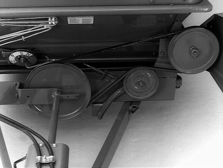
DRIVE BELT (Fig. 13)
IMPORTANT: The belt tension should be checked and adjusted after the first 10 to 15 loads, due to the effect of initial belt stretch and wearing of paint from the sheave grooves. Thereafter, it should be checked every 300 loads.
Adjust the belt tension by tightening the nuts on the Jbolt, Figure 13, until the compression spring is the length of the gauge, 2-1/2″ (64 mm).
Sudden shock loads can occur and can cause belt slippage. When this happens, determine the cause and clear the obstruction before attempting to restart the machine.
IMPORTANT: The belt should never be adjusted tighter than recommended as a means of starting a plugged Spreader. Also, tightening the belt excessively may result in damage to the Spreader.
DRIVE BELT REPLACEMENT (Fig. 13)
1.Open or remove the main shield as required.
2.Loosen the two jam nuts on the belt idler J-bolt.
3.Remove the old belts. ALWAYS replace belts in pairs.
4.Install the new belts by working them around the end of the drive shaft. Install both belts on the drive sheave BEFORE installing either on the driven sheave.
5.Place the lower strand of both belts on the idler.
6.To tension the belts, tighten the two jam nuts on the J-bolt, until the spring is compressed to the length of the spring gauge, 2- 1/2″ (64 mm).
7.Close or replace the main shield.
IMPORTANT: Check and adjust the new belts after 10-15 loads to compensate for initial stretch.
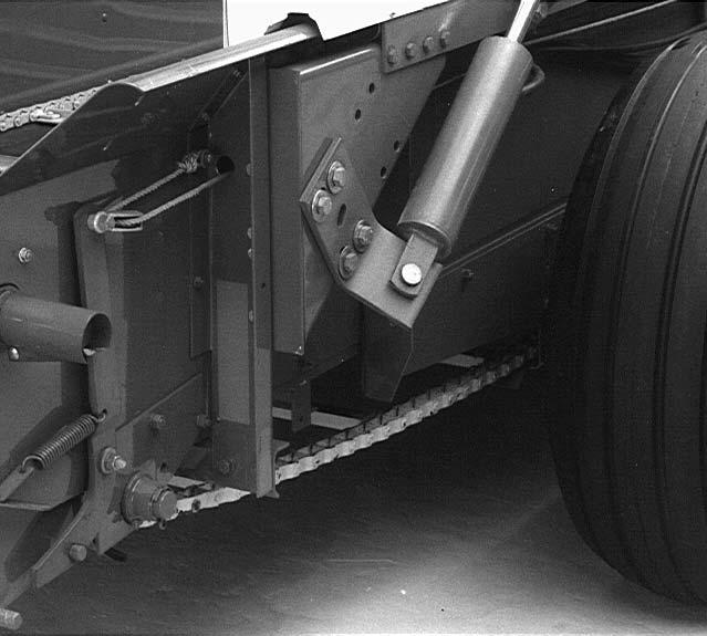
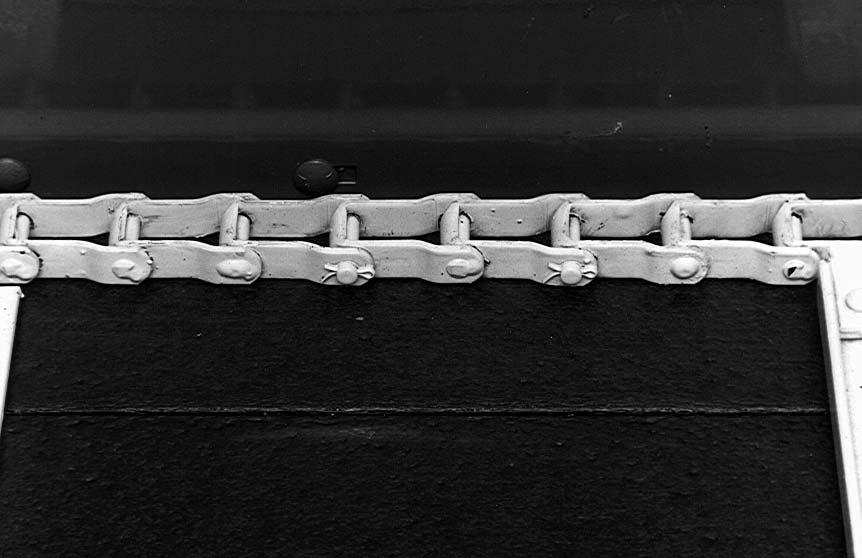
APRON CHAIN(S) (Figs. 14 - 18)
Periodically inspect the apron for bent or damaged slats. Always straighten or replace any bent or damaged slats immediately.
NOTE: Tighten the adjusting bolts equally on each side so the apron slats run parallel with the ends of the bed. The apron can be damaged if the machine is operated with one end of the apron slats running ahead of the opposite end. Do not tighten the apron chains excessively.
Single Chain Aprons
Adjust the apron by loosening the idler mounting bolts in Figure 14 or Figure 15, on both sides. Tighten the adjusting bolts on both sides until the chain slat clears the underside of the axle 1/2″ to 1-1/2″ (12.7 mm to 38 mm) on models 1177, 1217 and 1287. On model 1410, the apron chain should be adjusted to maintain a distance of 1/8″ to 3/8″ (3.2 mm to 9.5 mm) between the apron chain and support tube at the rear of the Spreader. Tighten the mounting bolts.
After the apron chain adjustment is completely used, the apron chain must be shortened.

The pintle chain can easily be shortened by removing two links on each side. Locate the chain coupler links with cotter pins, and remove. See Figure 16. A full range of adjustments is available for the apron chain.

The T-rod apron chain must be kept within the adjustment range of 1/2″ to 1-1/2″ (12.7 mm to 38 mm) below the axle at all times. A loose T-rod apron chain may disconnect if not properly tensioned.
The T-rod chain can be shortened when necessary by removing the chain tension, turning the chain at an angle, and removing the link. BE SURE to remove a link from both sides of the to keep the apron slats running parallel.
Double Chain Aprons (1410 ONLY)
The apron chains should be adjusted to maintain a distance of 1/8″ to 3/8″ (3.2 mm to 9.5 mm) between the apron chain and support tube at the rear of the Spreader.
On the double chain apron machines, adjust the center strands of the apron chains with the bolts shown in Figure 17. The top bolt adjusts the right chain, and the bottom bolt adjusts the left chain. Adjust the outer chains with nut, Figure 18, on each side of the Spreader. Adjust the outer chains after the center chains. Adjust so the front idler shafts are straight.


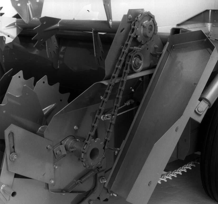
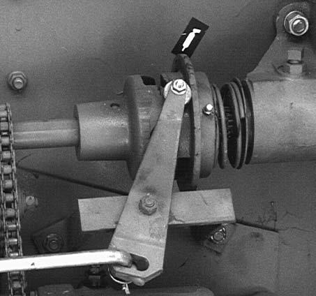
APRON DRIVE SHEAR BOLT (Fig. 19)
The apron drive is protected by a shear bolt. Refer to the individual model parts book for the proper shear bolt used in each model Spreader. Shearing of the bolt is usually due to the apron being frozen to the floor, or the slats catching on manure frozen to the floor.
An extra shear bolt is carried in the support as shown.
In some cases, the bolts will shear due to the Spreader being overloaded. If the bolt shears, the drive hub can be rotated counterclockwise until the bolt holes align. Always determine the cause of the failure, and eliminate it before installing the new bolt. Use a genuine GEHL shear bolt.
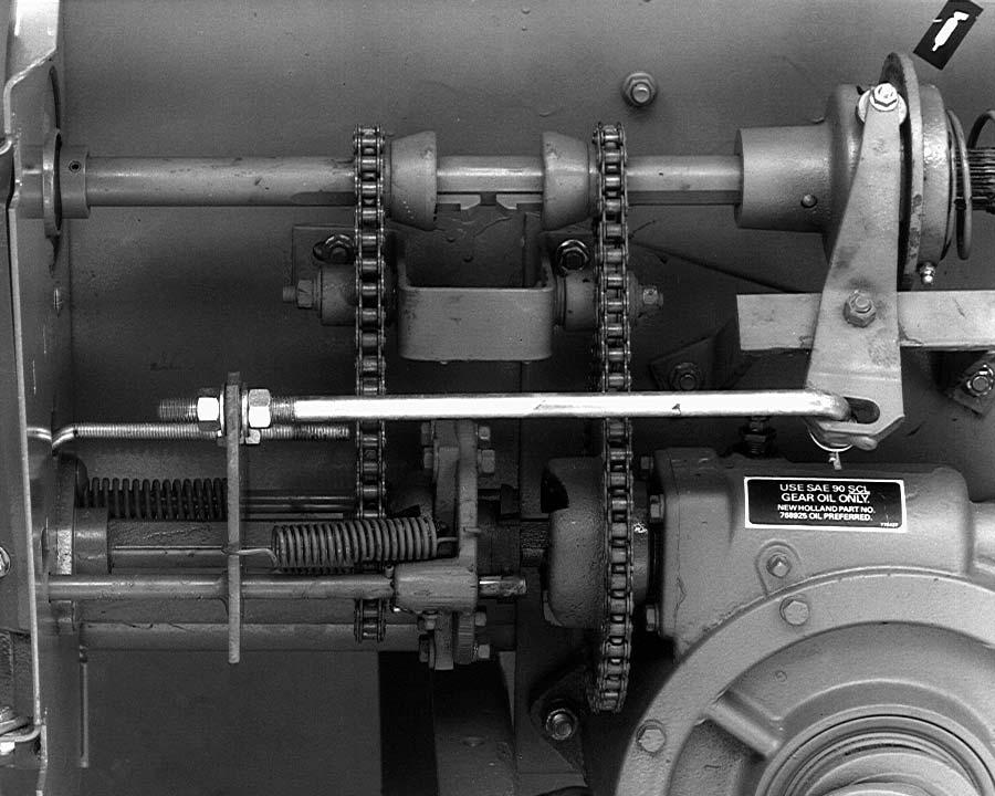
GEARBOX DRIVE CHAINS (Fig. 19)
Adjust the gearbox drive chains to deflect 1/4″ to 3/8″ (6.4 mm to 9.5 mm) with 5 lbs. (22 N) force at the mid-span of the chain. Adjust the chains by moving the idler blocks. DO NOT OVERTIGHTEN THE CHAINS.
Before tightening the worm gearbox drive chain, do the following:
1.Place the rotary quadrant in slow position.
2.Rotate the Spreader drive shaft in the direction of operation at least five revolutions.

3.Tension the worm gearbox drive chains.

FEED CONTROL (Figs. 20 - 22)
(Mechanical Drive Only)
Check the feed control system at the beginning of each season and adjust, if necessary, to compensate for wear. Be sure the control linkage always works freely.
Adjust the unloading speed linkage using the following steps:
1.Set the apron speed control quadrant in or slow position.
2.Rotate the drive shaft by hand until the clutch teeth and slow speed sprocket teeth engage as shown in Figure 20.
3.Adjust eyebolt, Figure 20, until the driving teeth of the shifting clutch are engaged fully with the teeth on the slow speed sprocket. Proper engagement is when both clutch and slow speed sprocket are flush to 1/16″ (1.6 mm) extended from the sprocket tooth.
4.Move the feed control quadrant to the position or fast apron speed. In this position the sliding clutch half should be fully seated in the front (high speed) sprocket, Figure 21.
5.Adjust the control rod, Figure 21, so the rollers just clear the beater clutch hub.
6.Move the feed control lever to “C”, cleanout position (beater not operating). There should be 1/8″ (3.2 mm) clearance between the beater clutch teeth. Adjust the length of the control rod, Figure 21, to obtain 1/8″ to 3/16″ (3.2 mm to 4.8 mm) clearance between the clutch jaws as shown in Figure 22.
7.Shift the rotary quadrant back to the neutral position. Run the Spreader at half speed while checking the various positions of the apron speed control to be sure all the adjustments are correct.
8.Close and secure the shield.
NOTE: When operating during freezing weather, lubricate all pivoting and sliding points to keep the controls operating freely.
Wheel Bearings
Adjust wheel hub bearings after 100 loads, and once each season thereafter.
Jack up the Spreader to remove the weight from the wheel(s). Torque wheel hub bearings to 35 ft. lbs. (47 N·m) while rotating the hub. Back off the nut one flat plus enough to install the cotter pin; 1/6 turn minimum, 1/3 turn maximum.
Upper Beater Drive Chain
The drive chain on the upper beater assembly should be adjusted to deflect 1/2″ (12.7 mm) at the center of the longest span with the chain at its tightest point.

Chapter 8 Lubrication Warning
NEVER lubricate the machine when any part of the unit is in motion. ALWAYS, BE SURE to follow the MANDATORY SAFETY SHUTDOWN PROCEDURE (page 8) BEFORE lubricating the machine.
A sufficient amount of oil or grease will prevent excessive part wear and early failure. Some of the photographs will show shields or guards removed for clarity. NEVER operate Spreader without all shields and guards properly installed.
NOTE: Whenever service is performed on hydraulic components (valves, cylinders, hoses, etc.) or transmissions, care must be taken to prevent discharging fluid onto the ground. Catch and dispose of fluid per local waste disposal regulations.
Transmissions
Periodically check the oil level in each transmission. In the beater drive transmission, replenish the oil, as necessary, with SAE #90 gear oil. For the apron drive transmission, use only special Gehl gear lube (part number 143499), 1.9 Qts. Special Gehl gear lube MUST be used to promote long life and avoid component breakdown and early failure.
Oiling
Lubricate all drive chains every 100 loads of operation (or monthly) using a good grade of foaming aerosol lubricant or clean motor oil. The recommended method is to spray the entire length of chain on the center of the rollers. It is better to lubricate chains when they are warm (after use, rather than before).
In addition to the roller chains, apply motor oil or foaming aerosol lubricant to the telescoping PTO drive guard and the upper beater drive chain (where provided).
Lubricate the apron chains with SAE #30 oil or similar lubricant at least twice yearly. If the Spreader is stored outdoors or if the manure being hauled is of a highly acid nature, more frequent lubrication will be required.
Greasing
Wipe dirt from the fittings before greasing to prevent any dirt from being forced into the bearings or pivots. Replace any missing fittings, when noted. To minimize dirt build-up, avoid excessive greasing.
IMPORTANT: In addition to the fittings, inspect and repack the wheel bearings at least once a year.
Oiling Locations
Oil Every 100 Loads (or Monthly)
1.Drive chains
2.Clutch arm rollers and pivot points, control arm linkage, belt idler pivot, and jack latch Oil Every 600 Loads (or Six Months)
3.Apron chain (more often if the manure is of high acid nature or if the machine is stored outside)
Grease Fitting Locations
NOTE: For the first week of operation, lubricate all fittings daily to ensure proper break-in of the drive components. Thereafter, lubricate all fittings at the prescribed intervals of operation listed. Use a good grade of lithium-based grease resistant to washing out under exposure to rain and other fluids.
Grease Every 100 Loads (or Monthly)
4.PTO universal joints
IMPORTANT: Use care when greasing universal joints, because seals may be damaged.
5.Telescoping section of PTO
6.Jack
7.Jackshaft (2 places)
8.Quadrant
9.Quadrant pawl
10.Propeller shaft bearing - 1177, 1217 (1); 1287, 1410 (2)
11.Wheel hubs - 1177, 1217 (2); 1287, 1410 (4)
12.Slow speed sprocket
13.Clutch (2 places)
14.Shifting clutch yoke (2 places)
15.Fast speed sprocket
16.Beater throw-out clutch
17.Input shaft - outboard bearing
18.Beater drive end
19.Apron shaft bearings (2 places)
20.Beater bearing
21.Optional upper beater bearings (2 places)
22.Double apron shaft center bearing (double apron models only)
Grease Every 600 Loads (or Six Months)
23.Tandem axle pivots on models 1287 and 1410 (grease with Spreader empty)
Transmission Oil
Check Every 600 Loads (or Six Months)
24.Apron drive gearbox check plug (use only Gehl part number 143499)
25.Beater drive gearbox check plug (use API GL-5 80W-90 oil)


The following lubrication locations have been repeated for your convenience.
Oiling Locations
Oil Every 100 Loads (or Monthly)
1.Drive chains
2.Clutch arm rollers and pivot points, control arm linkage, belt idler pivot, and jack latch Oil Every 600 Loads (or Six Months)
3.Apron chain (more often if the manure is of high acid nature or if the machine is stored outside)
Grease Fitting Locations
NOTE: For the first week of operation, lubricate all fittings daily to ensure proper break-in of the drive components. Thereafter, lubricate all fittings at the prescribed intervals of operation listed. Use a good grade of lithium-based grease resistant to washing out under exposure to rain and other fluids.
Grease Every 100 Loads (or Monthly)
4.PTO universal joints
IMPORTANT: Use care when greasing universal joints, because seals may be damaged.
5.Telescoping section of PTO
6.Jack
7.Jackshaft (2 places)
8.Quadrant
9.Quadrant pawl
10.Propeller shaft bearing - 1177, 1217 (1); 1287, 1410 (2)
11.Wheel hubs - 1177, 1217 (2); 1287, 1410 (4)
12.Slow speed sprocket
13.Clutch (2 places)
14.Shifting clutch yoke (2 places)
15.Fast speed sprocket
16.Beater throw-out clutch
17.Input shaft - outboard bearing
18.Beater drive end
19.Apron shaft bearings (2 places)
20.Beater bearing
21.Optional upper beater bearings (2 places)
22.Double apron shaft center bearing (double apron models only)
Grease Every 600 Loads (or Six Months)
23.Tandem axle pivots on models 1287 and 1410 (grease with Spreader empty)
Transmission Oil
Check Every 600 Loads (or Six Months)
24.Apron drive gearbox check plug (use only Gehl part number 143499)
25.Beater drive gearbox check plug (use API GL-5 80W-90 oil)