2 minute read
CHAPTER 9 SERVICE


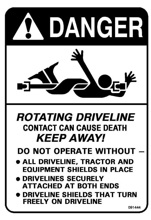
Warning
BEFORE performing service routines on this unit, follow the MANDATORY SAFETY SHUTDOWN PROCEDURE (page 8).
TIRES & WHEELS WARNING
Tire mounting, repair and replacements should only be performed by a qualified tire manufacturer’s representative, or by properly trained personnel following the tire manufacturer’s instructions.
Warning
Inflating or servicing tires can be hazardous. Whenever possible, trained personnel should be called to service or mount tires. To avoid possible death or serious injury, follow the safety precautions below:
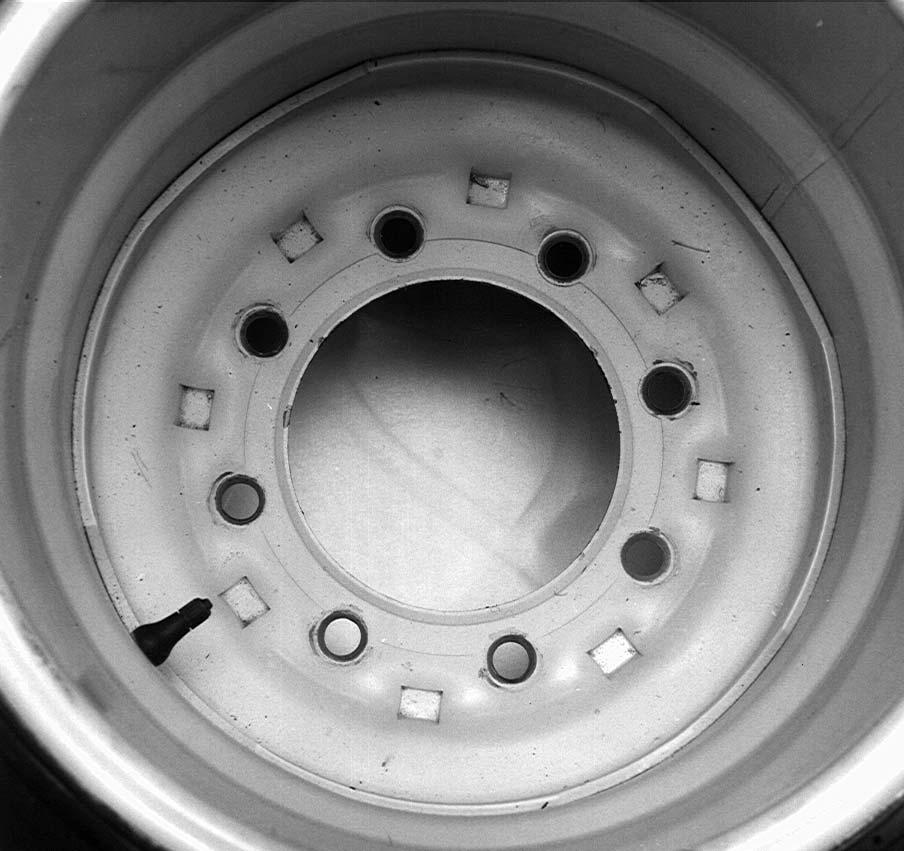
• BE SURE the rim is clean and free of rust. Lubricate both the tire beads and rim flanges with a soap solution. DO NOT use oil or grease.
• Use a clip-on tire chuck with a remote hose and gauge which allows you to stand clear of the tire while inflating it.
• DO NOT place fingers on the tire bead or rim during inflation.
Tire (Inflation) Pressures
• NEVER inflate beyond 35 PSI (241 kPa) to seat the beads. If the beads have not seated by the time the pressure reaches 35 PSI, deflate the assembly, reposition the tire on the rim, relubricate both parts and re-inflate it. Inflation pressure beyond 35 PSI with unseated beads may break the bead or rim with explosive force sufficient to cause death or serious injury.
• After seating the beads, adjust the inflation pressure to the recommended operating pressure listed.
• DO NOT weld, braze, or otherwise attempt to repair and use a damaged rim.
Check the Spreader tire pressure after every 50 hours of operation. Tires should be inflated to the pressure listed in the table. Wheel bolt torque should be checked after every 50 hours of operation and tightened to 120 ft-lb (163 Nm) torque. Heavy duty wheels should be torqued to 150 ft-lb (203 Nm) torque.
PTO INPUT SPEED - 1000 RPM
Models - 1177, 1217 & 1287 ONLY (Figs. 23 - 25)
To change the drive from 540 RPM tractor PTO to 1000 RPM tractor PTO, do the following:
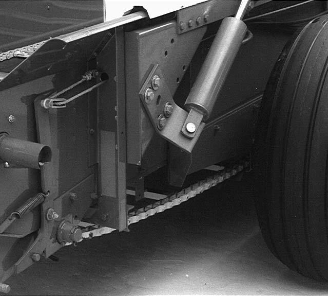
1.Loosen the drive belt and remove the drive shaft assembly, Figure 23, from the Spreader.
2.Remove the drive sheave from the rear of the drive shaft.
3.Remove the driven sheave from the propeller shaft. Install this 12-1/2″ (318 mm) sheave on the rear of the drive shaft.
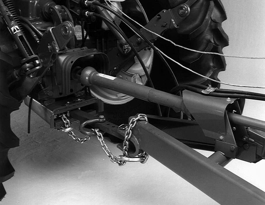
4.Torque the castellated nut to 20 ft. lbs. (27 N·m). Back off the nut two flats, plus enough to install the cotter pin. Reinstall the drive shaft assembly on the Spreader as shown in Figure 24.

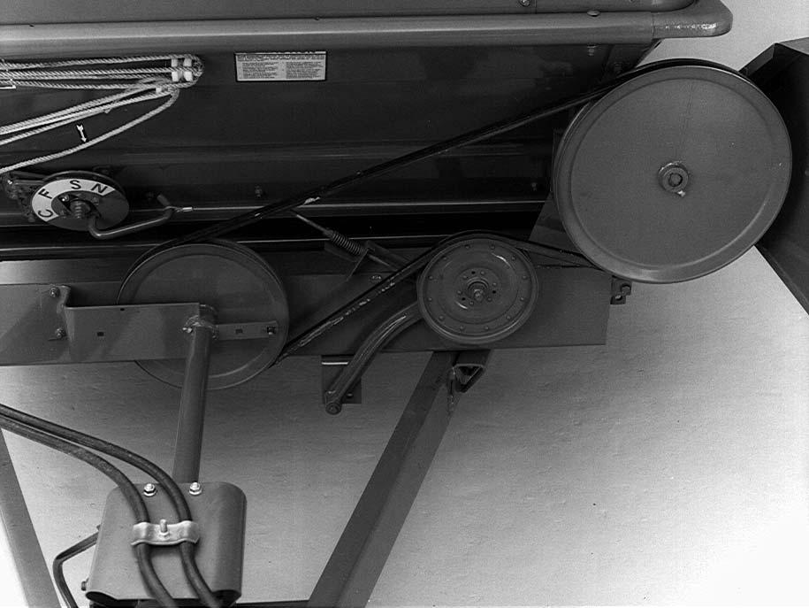
5.Move the belt idler pivot from the position shown in Figure 23 to the position shown in Figure 24. Remove the belt shield. Reinstall it in the outer position as shown Figure 25.
6.Install a new 16-3/4″ (425 mm) sheave, Figure 24, (available from your dealer) on the propeller shaft. Align it with the drive sheave.
7.Reinstall the drive belt and adjust the belt tension so the spring is compressed to the length of the gauge or 2-5/8″ (67 mm). See Figure 24.
8.Close and secure the shield.
9.A 1000 RPM front PTO section must be installed (available from your dealer).
1
12-1/2″ (318 mm)
16-3/4″ (425 mm)